00:04
The inline bank is a control object that can be used to act as a connection between 1D and 2D parts of the network.
00:12
The bank line is drawn where the coupling takes place,
00:15
and the inline bank link is drawn in the direction of flow, so that it intersects the bank line.
00:22
To begin, from the File menu, select Open > Open transportable database.
00:29
Navigate to the folder where you downloaded the exercise files for this tutorial,
00:34
select the .icmt file, and then click Open.
00:40
If you see a popup about opening the database as read-only, click Yes.
00:46
In the transportable database window, right-click the top-level folder, and select Copy.
00:53
In the popup, click Continue.
00:56
Right-click the Database and select Paste (with children).
01:01
In the Copying pop-up, enable Copy ground models.
01:07
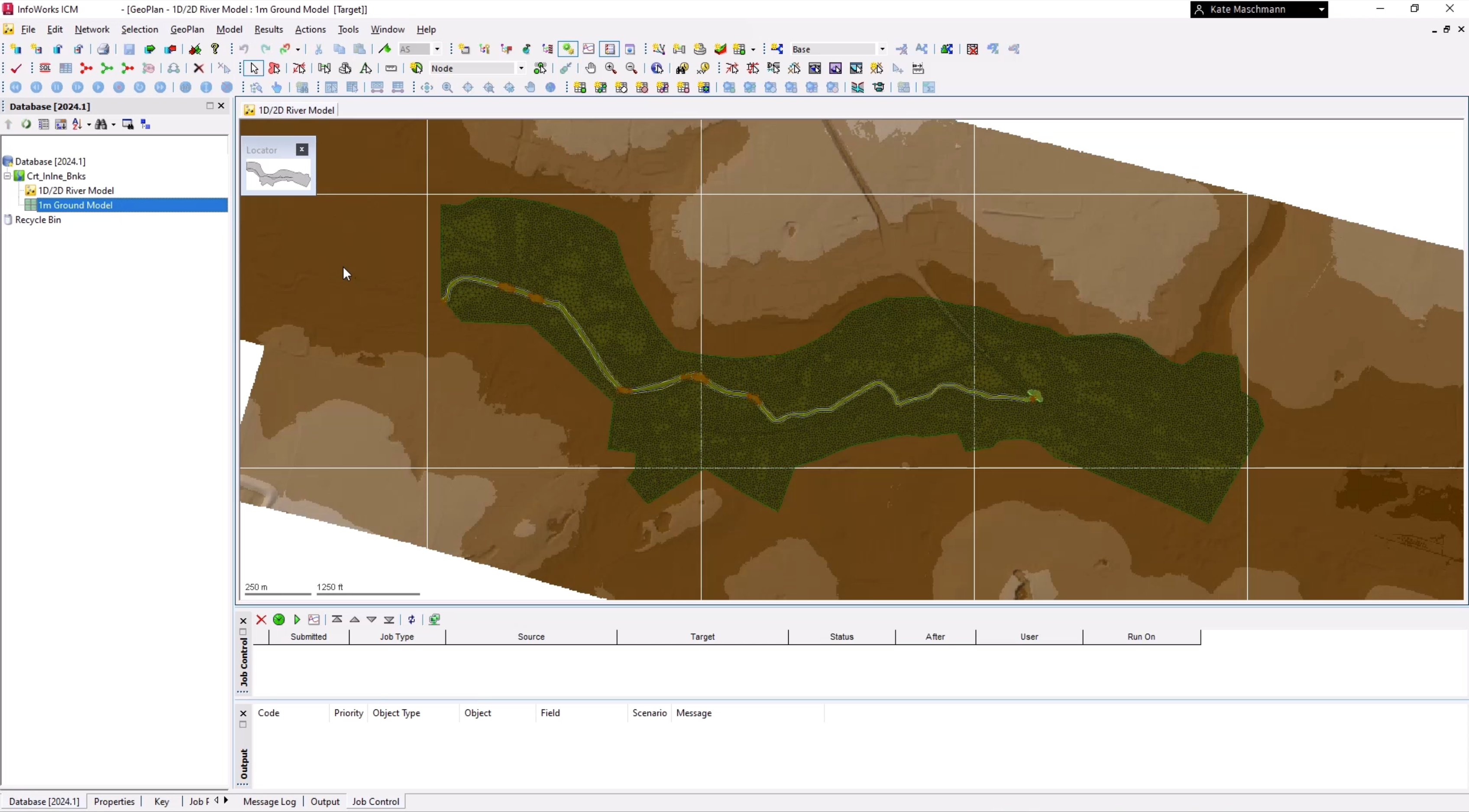
In the Explorer window, double-click 1D/2D River Model to open it on the GeoPlan.
01:15
From the Database, drag 1m Ground Model and drop it onto the GeoPlan.
01:22
To begin, from the Network menu, click Import > Open Data Import Centre to open the ODIC.
01:32
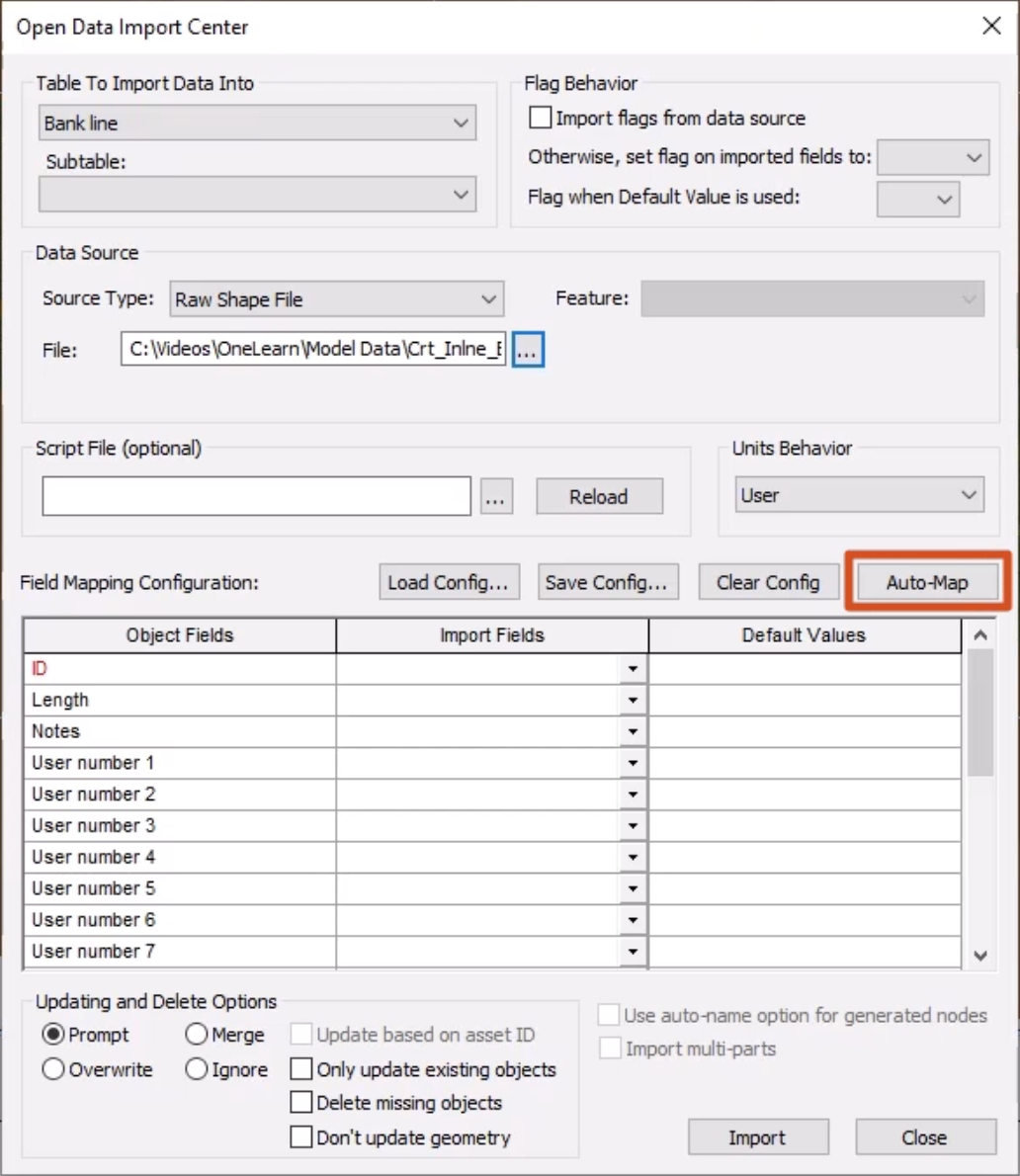
In the Table To Import Data Into drop-down, select Bank line.
01:38
Under Data Source, ensure that the Source Type is set to Raw Shape File.
01:45
Click the More (…) button, navigate to the exercise files for this tutorial,
01:52
select Bank Lines.shp, and then click Open.
01:57
In the Field Mapping Configuration section, click Auto-Map to search the import file for fields that match.
02:06
Click Import, and then OK to close the notification.
02:13
In the GeoPlan Tools toolbar, click Find in GeoPlan and perform a Quick Find for Culv_Out.
02:22
Once the node is located, Close the Quick Find window.
02:26
This is where the two bank lines, shown in yellow, were imported and will be used to create the inline banks.
02:34
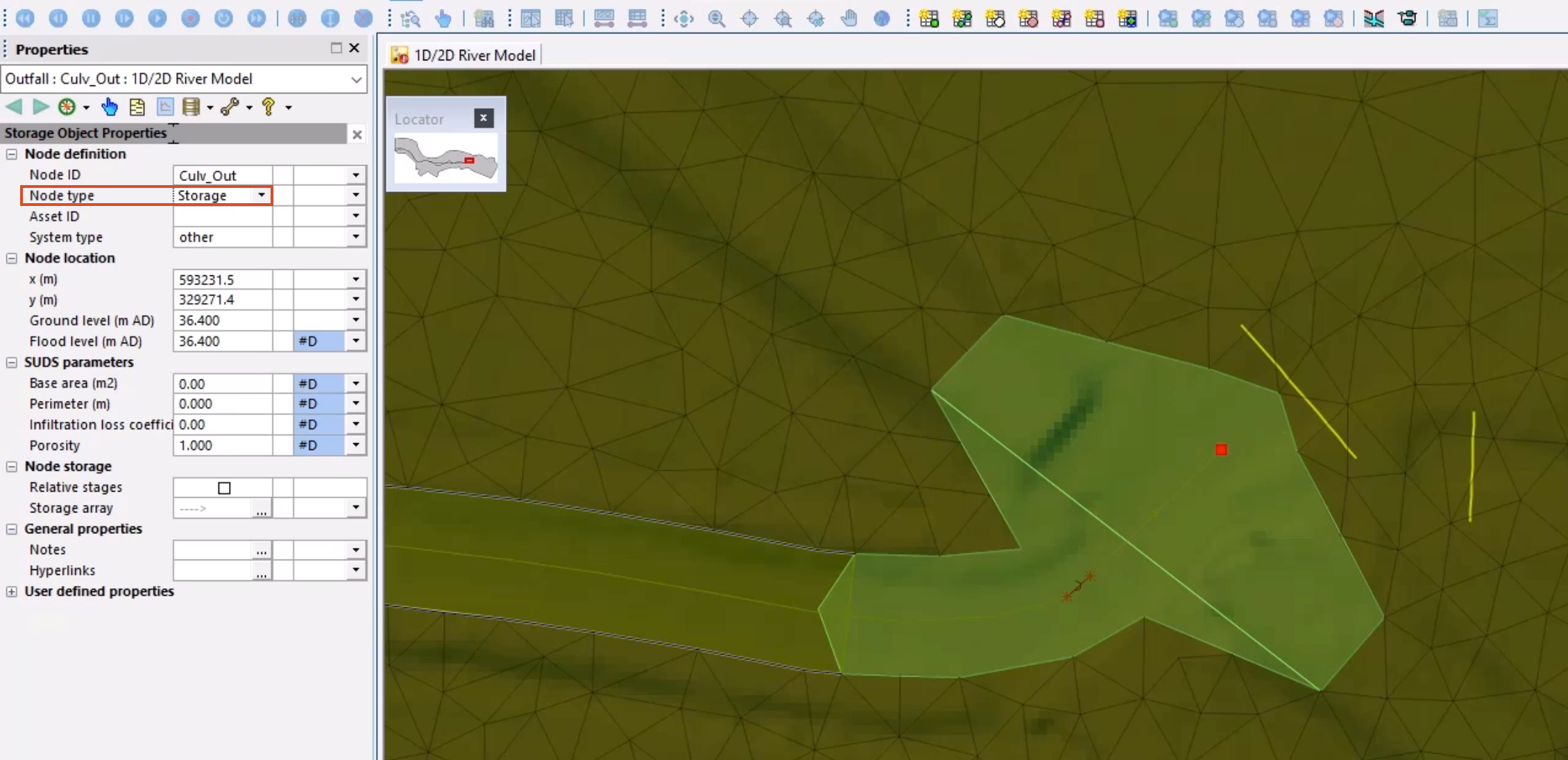
Double-click Culv_Out to open the Properties window.
02:38
Change the Node type to Storage.
02:41
This is to prevent the flow being lost at the outfall.
02:46
Zoom out slightly to view the extents of the storage area polygon.
02:51
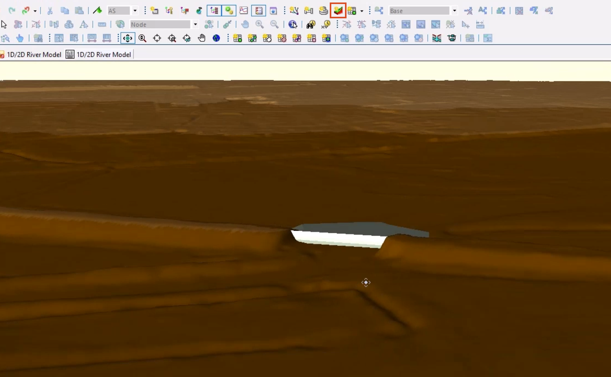
From the Windows toolbar, click New 3D network window
02:56
to view a 3D representation of this culvert in relation to the ground model.
03:01
Navigate with the viewpoint.
03:04
The embankment has been filtered out of the ground model, which is a common issue.
03:09
If you simply meshed this area, it would allow flow through the gap.
03:14
This is why the storage area is present, to void this area.
03:19
Notice the area downstream of the river becomes flatter and the channel is less defined,
03:25
making this more appropriate for 2d representation.
03:30
Close the 3D View window.
03:33
You can now create two new outfall nodes on the right-hand side of each bank line.
03:39
From the GeoPlan Tools toolbar, expand the New Object Type drop-down and select Node.
03:48
Click New Object and to the right of the first bank line, add a node.
03:55
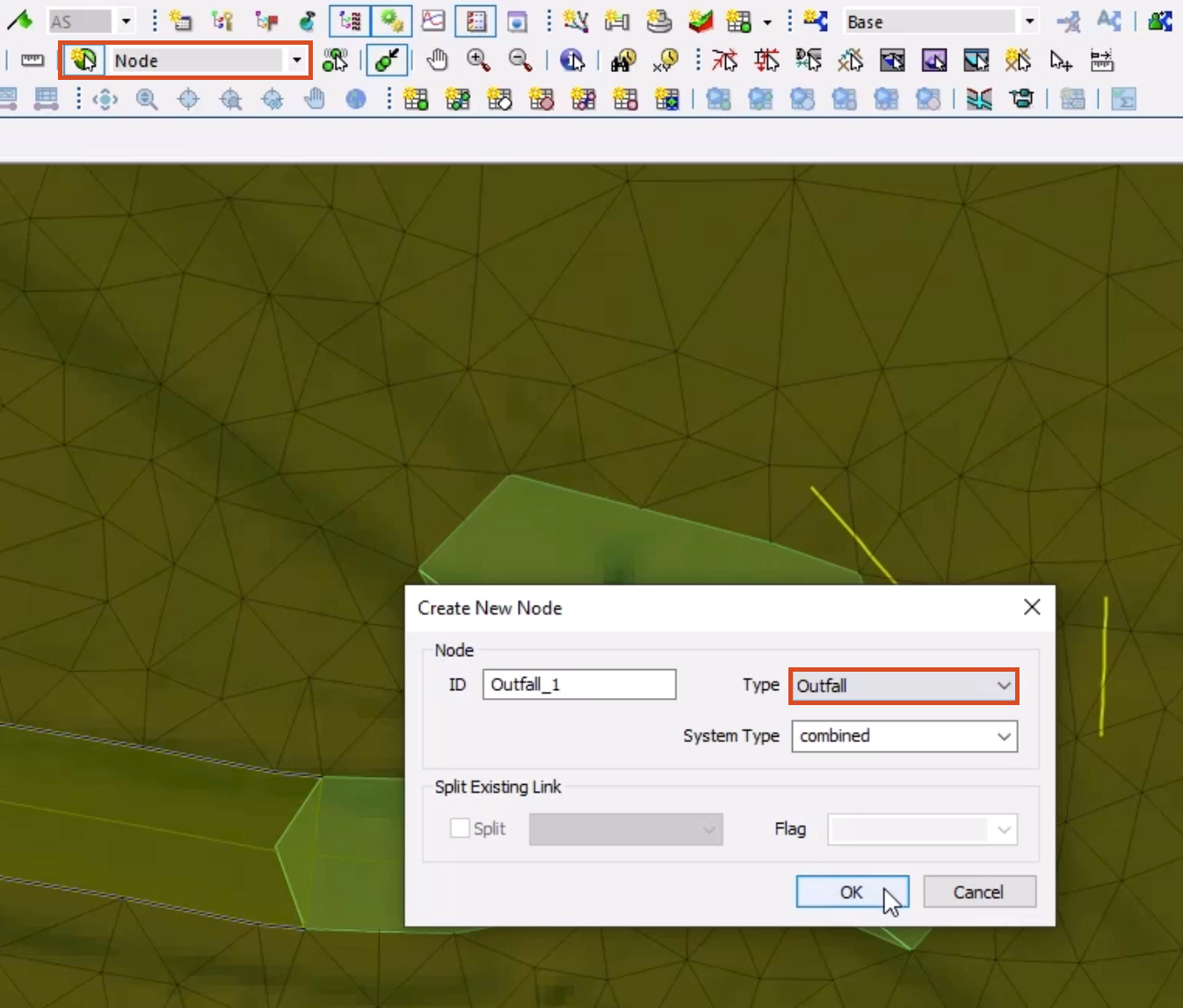
In the Create New Node popup, add an ID of “Outfall_1”.
04:01
Set the Type to Outfall, being careful NOT to select Outfall 2D, and then click OK.
04:09
Add another node to the right of the second bank line with an ID of “Outfall_2”.
04:16
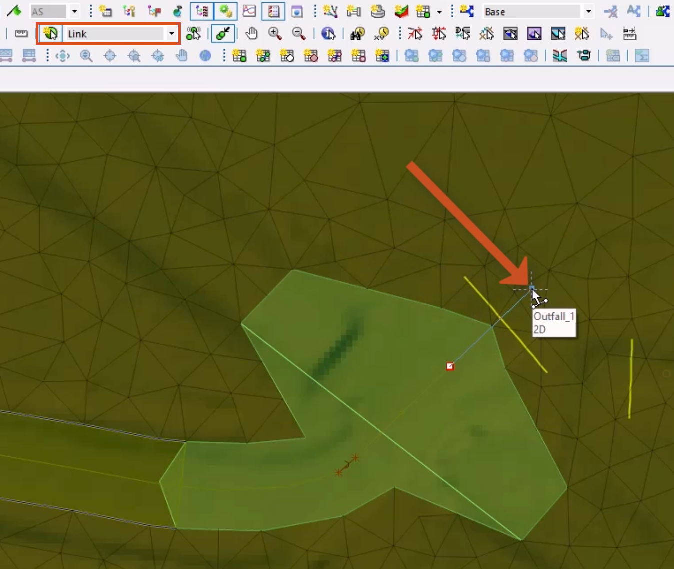
In the New Object Type dropdown, select Link.
04:21
Click New Object and draw a link from Culv_Out to the first added outfall node.
04:28
In the Create New Link popup, set the Type to Inline bank, and then click OK.
04:35
Repeat this step for the second node, drawing the link from Culv_Out to the Outfall_2 node.
04:42
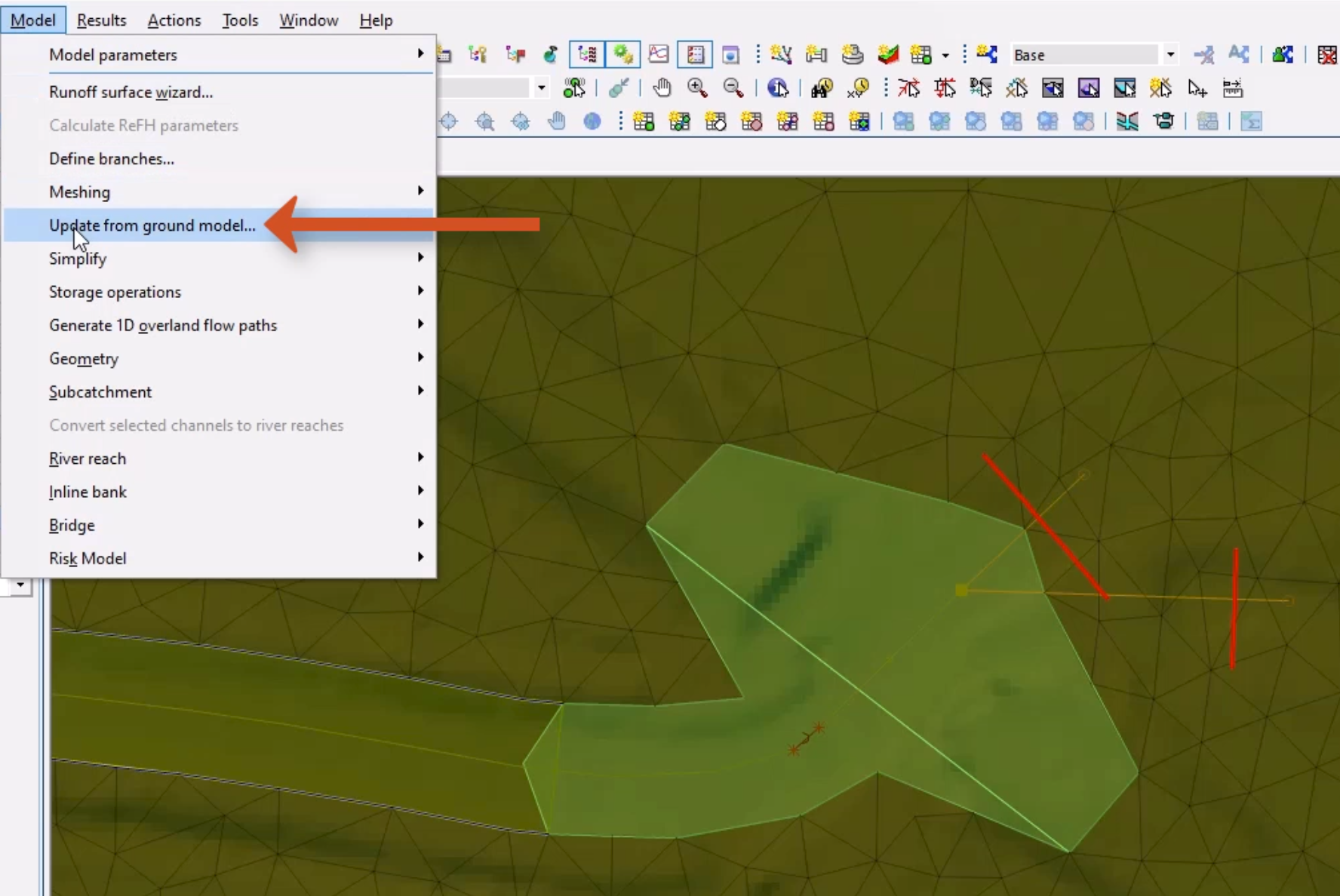
Click the Select tool, and then press and hold CTRL as you click the two bank lines to select them.
04:51
From the Model menu, select Update from ground model.
04:56
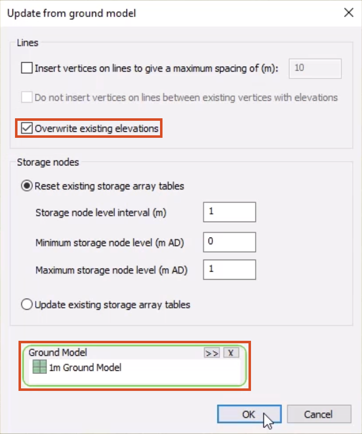
In the Update from ground model dialog, enable Overwrite existing elevations.
05:02
The Ground Model should be automatically populated.
05:07
Double-click one of the bank lines to open the Properties window.
05:12
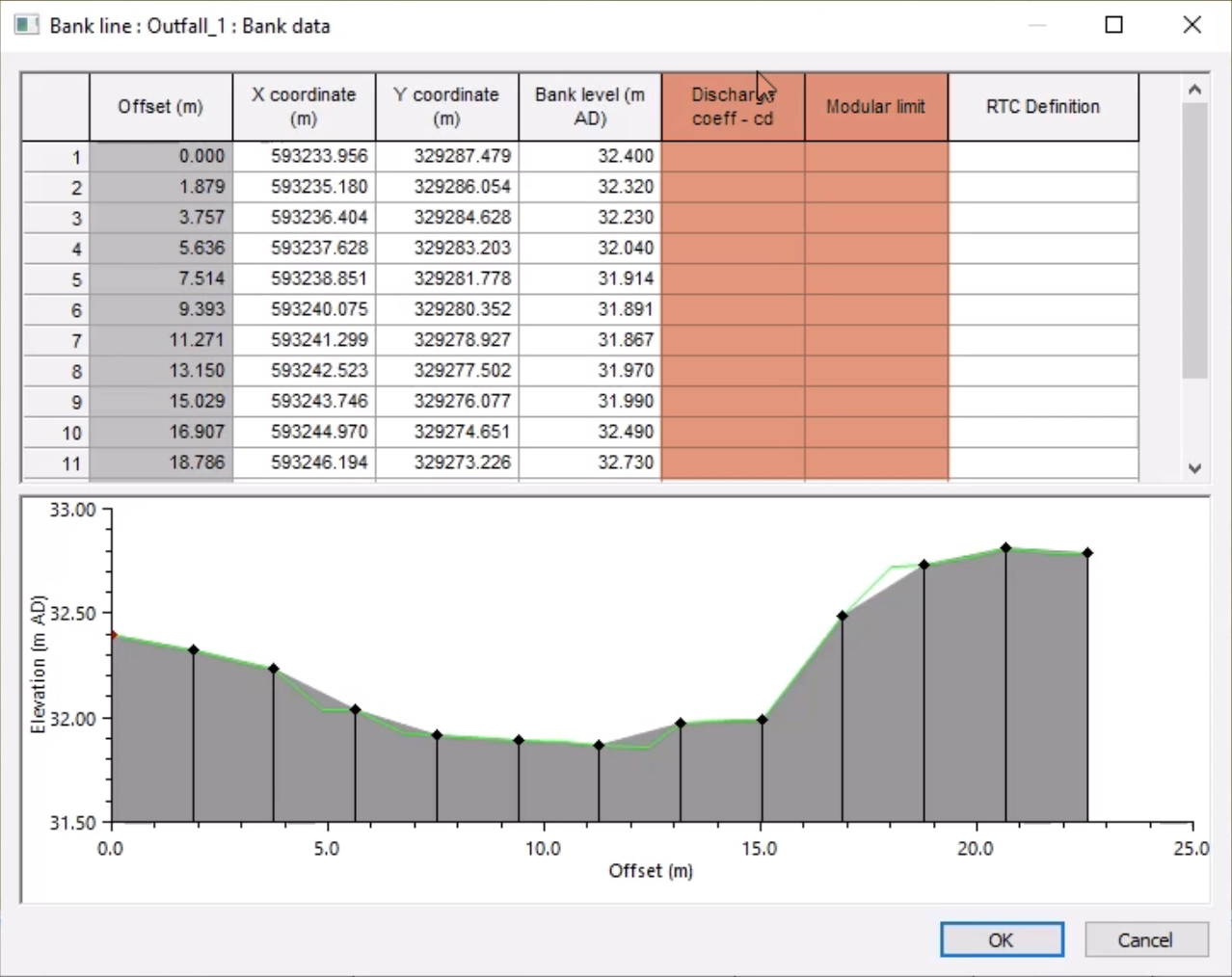
In the Bank data field, click More (…).
05:16
In the Bank data window, you can see that the Bank level data now exists,
05:21
but the discharge coefficient and modular limit fields are blank.
05:27
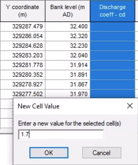
Select the Discharge coeff – cd column header to select all cells in the column.
05:34
Right-click one of the cells, select Set new value(s) for cell(s),
05:41
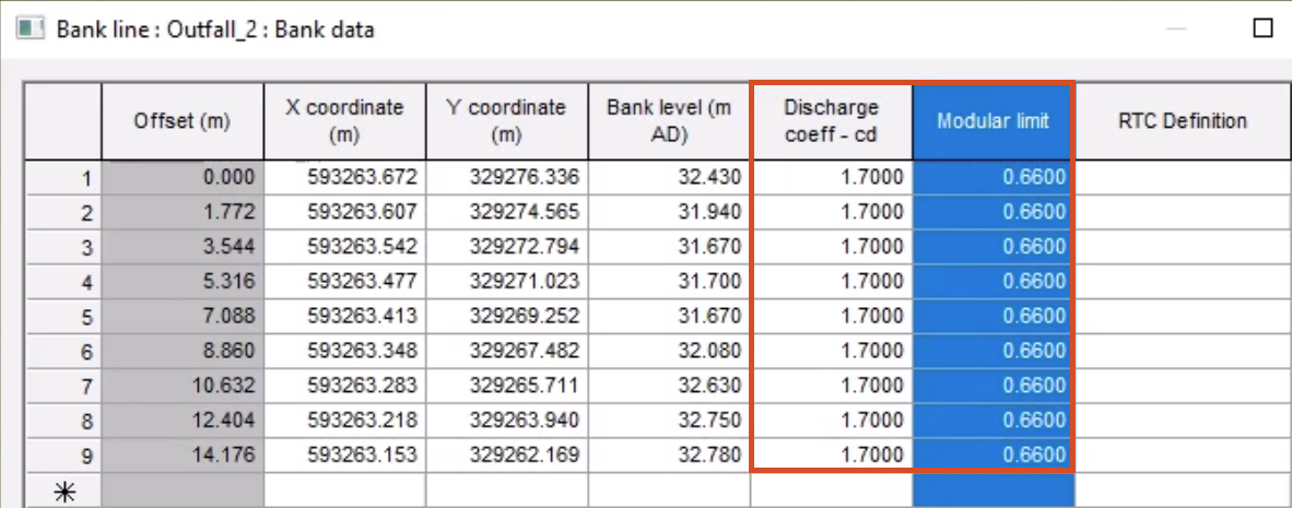
and then set a new value of 1.7. Click OK.
05:48
Repeat this step for the Modular limit column, setting a value of 0.66.
05:55
Repeat for the second bank line.
05:60
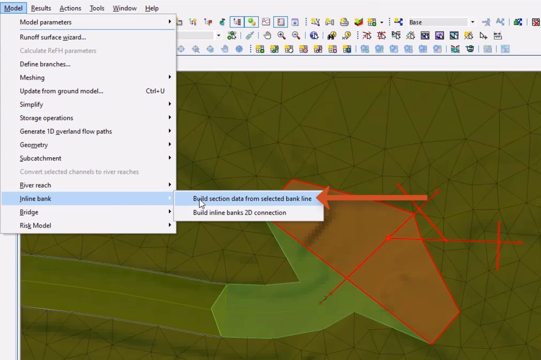
Using the Select tool, drag to select the inline banks and corresponding bank lines.
06:11
From the Model menu, select Inline bank > Build section data from selected bank line.
06:19
You can see that the process is complete when the inline bank creates a dotted line over the bank line.
06:27
With bank lines imported and inline banks created and populated with the bank line geometry
06:34
the next step is to build their connection to the inline banks.