Step-by-step guide
UPC scripts allow you to represent the valves and pump stations within a water supply system that may be controlled by a more complex set of rules with multiple conditions. This example uses a UPC script to set two different types of pump controls, depending on the time of day.
- From the Model Group window, expand the UPC Model group.
- Double-click the UPC Network to open the UPC Network and UPC Control.
It is best practice to test UPC scripts in a scenario first, before altering a base model. To create a new scenario:
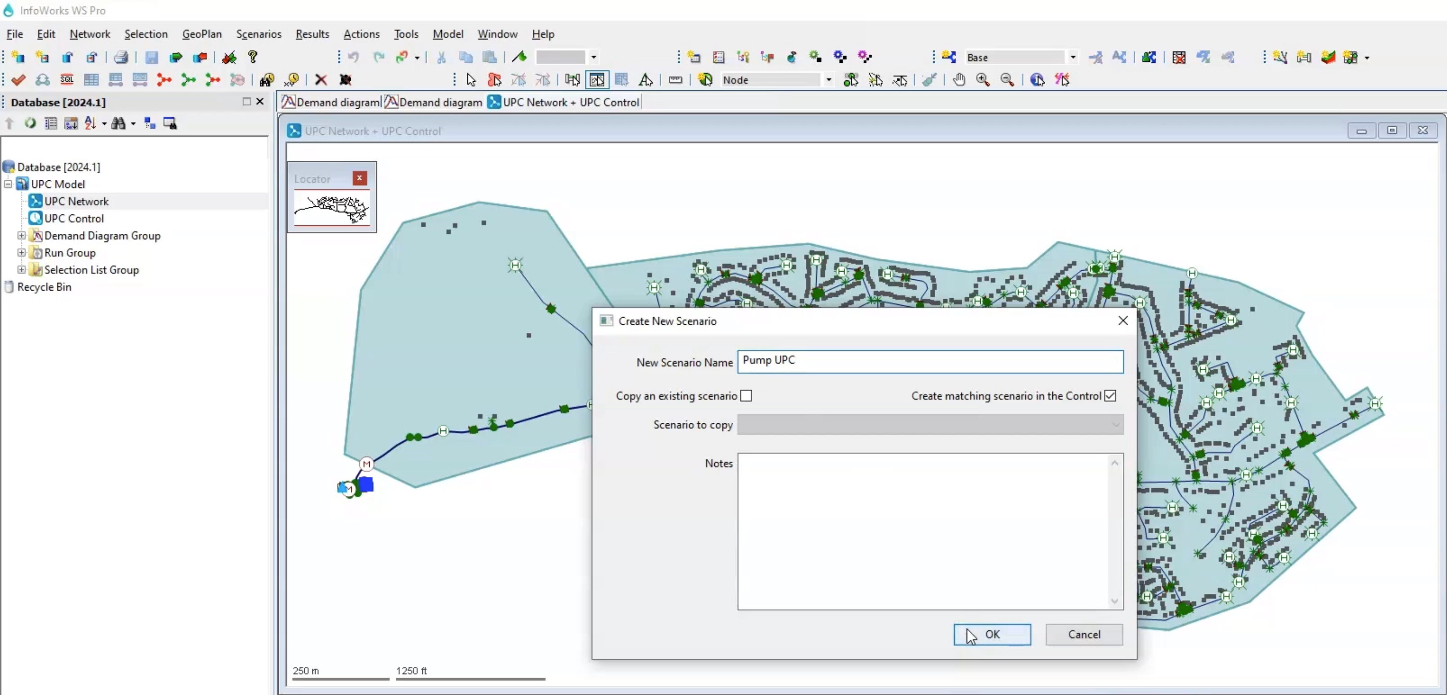
- In the Scenarios toolbar, click Create scenario.
- In the Create New Scenario dialog box, in the New Scenario Name field, type “Pump UPC”.
- Enable Create matching scenario in the Control.
- Click OK.
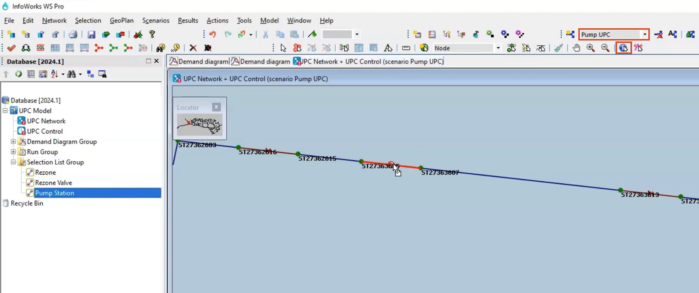
In the Scenarios toolbar, the Pump UPC scenario now appears selected in the drop-down.
- From the Model Group, drag the Pump Station selection list and drop it onto the GeoPlan to identify the pump station with asset ID 595311.
- In the Tools toolbar, click the Properties tool.
- On the GeoPlan, select asset ID 595311 to open the Properties window.
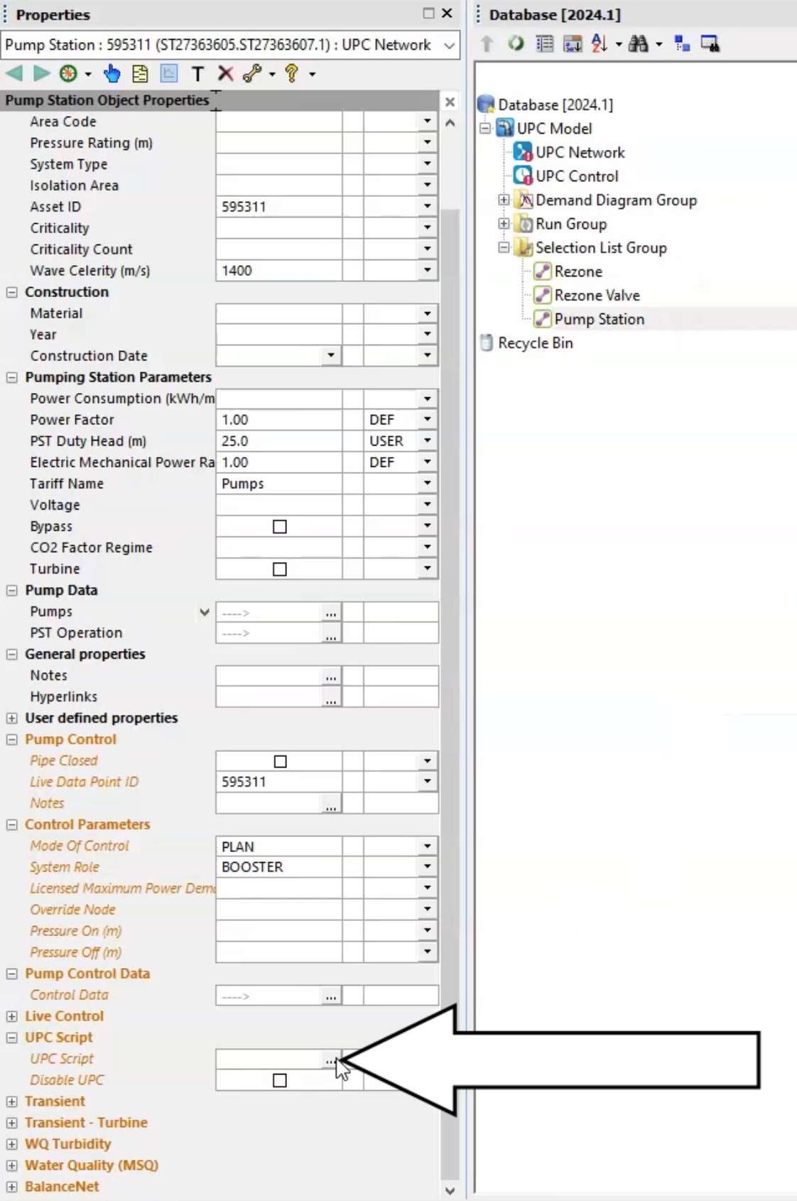
Next, create a UPC script that sets two rules for this pump—one to turn the pump on and off to maintain a pressure between 31 and 33 meters at the hospital between 06:00 and 22:00; and another to maintain a pressure of 27 m at the furthest node in the network (END) between 22:00 and 06:00.
- In the Properties window, expand UPC script.
- In the UPC Script field, click the More (…) button to open the UPC Script window.
- From the dataset provided for this tutorial, open the Pump UPC.txt file.
- Copy the lines of code provided.
- In the UPC script dialog box, Paste the code into the text field.
- Click Test to check for errors or syntax warnings.
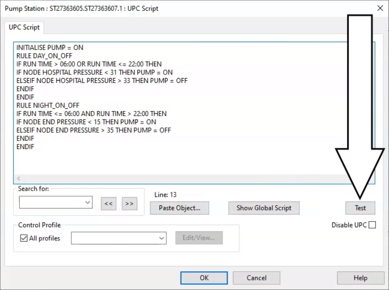
- When the message reports no warnings or errors, click OK.
- Click OK again to close the UPC Script window.
- Commit the changes to the database.
To run both scenarios:
- In the Model Group, right-click the Run Group and select New > Run.
- In the Schedule Hydraulic Run dialog box, in the Title field, enter “Pump UPC”.
- Enable Experimental.
- From the Model Group, drag the UPC Network into the Schedule Hydraulic Run dialog box and drop it into the Network group box.
- Click the Scenarios tab.
- Enable the Base and Pump UPC scenarios.
- Click Save.
- Click Run.
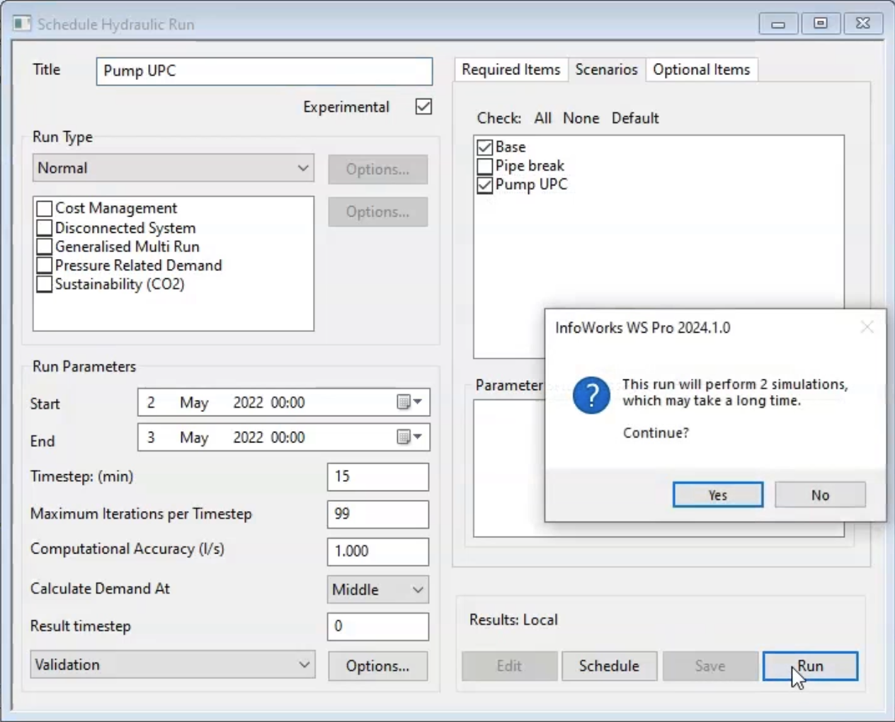
- In the notification, click Yes.
- When it finishes, from the Model Group drag the Base simulation into the GeoPlan.
To create a graph to visualize the results:
- In the Model Group, right-click the Pump UPC simulation and select Open as.
- In the Select Results popup, select As Alternate Results For Comparison.
- Click OK.
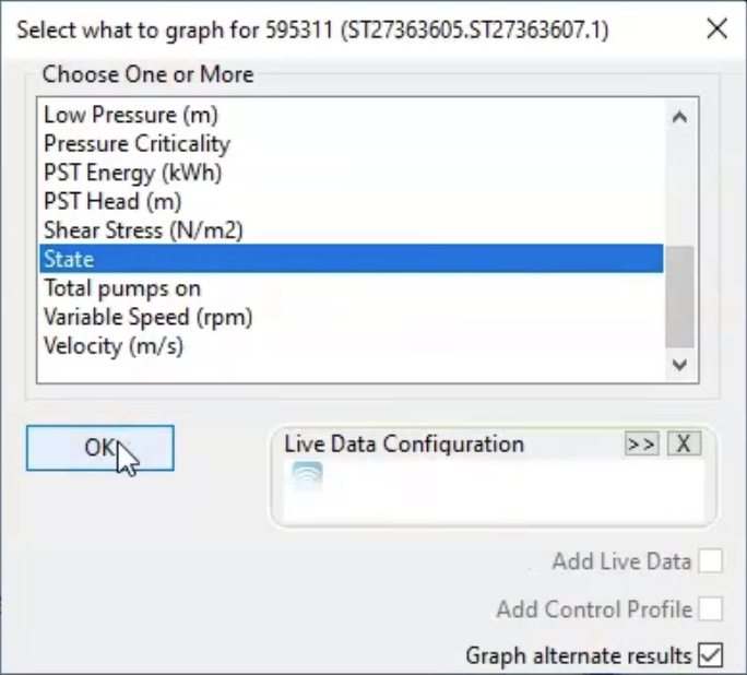
- On the Operations toolbar, click Graph selected objects.
- In the GeoPlan, zoom in and select the pump station.
- In the dialog box, select State.
- Enable Graph alternate results.
- Click OK.
A graph window opens, showing the state of the pump in the different scenarios.
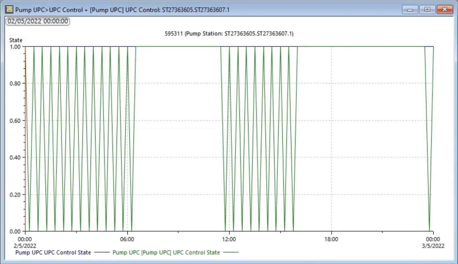
The base simulation pump remains on for the whole simulation, since its state is continuously set to 1. In the Pump UPC scenario, the pump turns on (1) and off (0) as the pressure at the specified control points change. Also note that a pump turning on and off with this frequency in reality could damage the distribution infrastructure, so the scheduling in this UPC might need to be refined.


