00:08
In this exercise, we will be assigning contacts to a Inventor Nastran analysis.
00:16
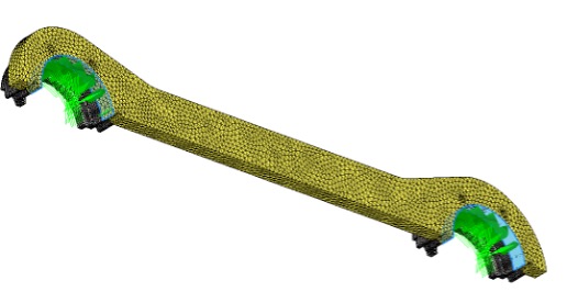
For this exercise, we'll be working with this Yoke assembly.
00:20
It is actually five total components.
00:23
So, looking at the assembly in the model tree, you'll see the two components here and then the subassembly has three parts as well.
00:30
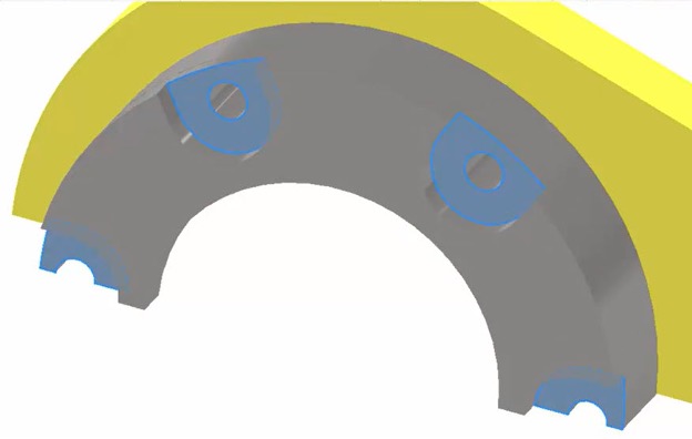
So, there are five separate solid bodies that we will need to connect using contacts to properly solve this FEA.
00:39
Another thing to note with this analysis is that this assembly has been cut into a quarter symmetry model,
00:46
which means it's been cut along two planes.
00:48
The first I have labeled here as the Z symmetry plane.
00:52
So, you can see this entire part has been cut down its middle along its length.
00:57
So, there will be a symmetry constraint applied on that back face there called Z symmetry.
01:03
The other cut plane here, I've labeled Y symmetry.
01:07
So, on the other side here, all of the components have been cut along the Y symmetry plane.
01:13
So, we will need a symmetry constraint on that surface as well.
01:17
And then we will be applying a fixed constraint to the areas where these parts will be bolted together.
01:24
So, for the boundary conditions, I'll work through this fairly quickly.
01:27
I'm going to start with my symmetry constraints.
01:30
So, along the plane called Z symmetry, I'll activate constraints, I'll select that face.
01:37
And then for the symmetry condition, I'll select "Symmetry Z" and I'll rename it Z symmetry as well.
01:44
So, I know what it is.
01:46
In the subcase, you can activate the glasses and update the density of the icons if you want to be able to see better.
01:53
But that's all I really need for that one.
01:54
So, I'll select "Ok", I'll also need symmetry along the Y plane here,
01:60
which is going to be all of the faces touching that Y symmetry plane, which is quite a few.
02:05
So, I work my way through selecting those as well and I'll rename the Constraint "Y Symmetry".
02:10
I'll select "y" underneath "Symmetry" in the dialogue box,
02:15
and then I'll just go through and start selecting all of those faces,
02:20
everything that is touching that plane.
02:23
So, take your time on this, make sure that you've selected all the faces you need to,
02:29
as you work your way along, you can always go back and double check,
02:32
but just be careful as you're making these selections not to select anything that is not touching that plane.
02:41
So, it looks pretty good. That should be all the faces of the parts and the subassembly that are touching that Y symmetry plane.
02:47
It looks pretty good.
02:48
So, I'll select "Ok".
02:50
And it's added into the subcase.
02:54
And then lastly, I'm going to go ahead and fix the faces that would be clamped down and not subjected to any rotation or sliding.
03:03
So, I'll go to constraints,
03:05
and I'll add a fixed constraint onto all of these flat faces here that will be clamped down with a bolt that we have not modeled.
03:12
So, that's going to create enough pressure to fix that face.
03:16
So, I'll select those four there.
03:17
And then same thing on the other side here of the assembly, all four of those faces as well.
03:24
So, eight total in this constraint, I'll rename to fix.
03:28
So, I know exactly what that is and then select "Ok".
03:32
And now I have my constraints here in my "Subcase 1".
03:37
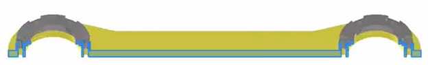
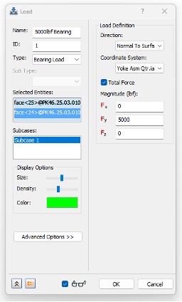
So, now I'm ready to add my bearing load to the yoke component.
03:41
So, to do that, I'll go ahead and select loads and the type here is going to be a bearing load.
03:48
So, I'll change the type to Bearing.
03:50
I'm going to rename this "5000lbf Bearing".
03:56
And then for Selected Entities rotating this part around,
03:60
I'm going to select the kind of curved phase here of the yoke on this side,
04:05
and then the other side will receive that same selection as well.
04:10
But notice because I'm applying 5000 pound-force total, I need to check the box right here under load definition for total force.
04:18
Otherwise, it will be 5000 pound-force per entity, but I want it to be 5000 pound-force total.
04:24
So, I'll activate that check box and for direction, it will be the positive y direction 5000 pound-force and turning on the glasses.
04:32
You can then see that load applied to both of those faces, essentially 2500 pound-force each.
04:39
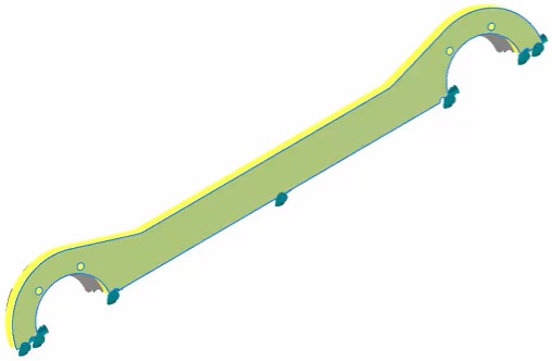
So, I'll select "Ok", once I'm ready to go and now my boundary conditions are complete.
04:46
bBefore I go any further, I am going to turn the visibility of the planes and the boundary conditions off.
04:51
So, it's a little bit cleaner and easier to see what I'm doing with contacts.
04:56
So, I'm going to go to "Object Visibility" and I'm going to deactivate Constraints, Loads.
05:01
That looks pretty good. And I'm just going to go ahead and right click on these planes and then turn their visibility off.
05:06
It's usually the easiest way to do it.
05:08
I can always bring them back in later if I need them, but that should be good to go and now I can go ahead and add in some contacts.
05:16
So, for this assembly, I'm going to use primarily automatic contacts,
05:20
but I will make some adjustments to the settings and the overall contact type specified.
05:26
To start, I always edit my Analysis.
05:28
So, I'll right click and go to edit.
05:32
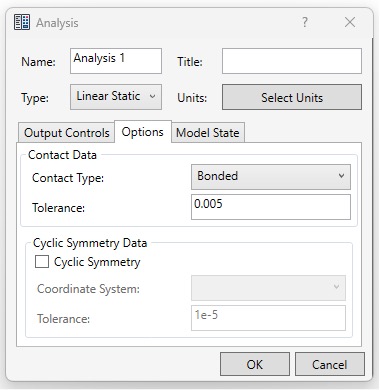
I go to the Options tab and this is where you see Contact Data Bonded and a Tolerance of 0.1 millimeters or 0.0039 inches.
05:42
I'm going to update this to be 5/1000 of an inch,
05:46
which means any surfaces that are 5/1000 of an inch away from one another will automatically receive a bonded contact type.
05:54
I like to adjust the tolerance to make sure I know what that number is and it's not a guessing game.
05:60
So, I'll then select "Ok".
06:01
And now when I run automatic contacts, it should use that 5/1000 of an inch tolerance.
06:06
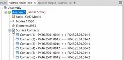
So, I'll click on auto contacts from the panel.
06:11
And now over in the analysis tree, you'll see "Surface Contacts" folder.
06:15
If I expand it, you'll see there are six contacts created.
06:19
The first one here is between, looks like the lip of this first part and then the lip of the next.
06:27
Should be the same thing on the other side.
06:30
Got a couple of surface contacts between the face of the yoke and then the face of the next subassembly.
06:38
So that looks pretty good.
06:40
It's just mostly picking up those planes, those larger surfaces that are touching one another.
06:44
So, I'll leave that for now and I can always come back and fine tune this by adding additional contacts or editing these current contacts later.
06:52
But I like to solve the analysis first to make sure that there aren't any instabilities in my constraints,
06:59
or my basic contacts before I begin fine tuning it.
07:05
So, at this stage, I'll just select "Save" to save my changes and then now I can go ahead and run.
07:17
So, the analysis completes I will select "Ok".
07:19
And now it should show my Von Mises stresses and displacement.
07:23
What it's going to do by default is exaggerate the deformation.
07:27
So, I'm going to go to the top panel here and turn deformed shape off just so that I can see the stresses.
07:36
And this will make it a little bit more clear.
07:37
I don't have such a weird image that I'm looking at.
07:40
I can see the high stress is kind of here near the edge of that constraint at that sharp corner should be pretty symmetric.
07:48
So, I should see a similar result on the other side.
07:51
When you're working with a model, it's mostly symmetric. That's what you want to see.
07:55
If for some reason something looked off, I would go back and double check my constraints, but this all looks pretty good.
08:01
So, at this stage, I can then decide if I want to make any adjustments to my contacts before I do that,
08:08
I'll just double check displacement real quick.
08:12
And that looks reasonable, right? I'm not seeing like 10 inches of displacement.
08:16
I'm seeing less than 1/1000 of an inch, which is what I would expect from a linear static stable model like this.
08:23
So, I'm good for now, I'll go ahead and save my results as they are.
08:28
And then now I'm ready to fine tune the contacts.
08:32
So, to determine what changes I want to make to these contact sets.
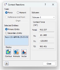
08:36
One really useful tool from inventor Nastran 2024 is the ability to look at contact reaction forces.
08:44
So, for instance, Contact 1 here,
08:47
if I right click and I go to "Contact Reactions", it'll tell me some of the forces that this contact is seeing.
08:55
So, it's seeing about 126 pound-force in the negative Y.
08:59
So, as this lifts upwards, it's holding it down in the negative Y direction.
09:04
And then also quite a bit of force in the Z direction about 900 pound-force in the positive Z.
09:10
So, it's trying to move away in the Z and this is keeping it in that direction.
09:17
So, looking at that face, that contact, if I take a closer look at it, I'll right click and edit the contact.
09:25
It's between this face here and then this small lip face right there.
09:29
Now, those faces are touching, but they are not bonded together.
09:36
There's nothing that is welding those two faces together, they should be able to slide and separate.
09:42
Because I've applied a bonded contact it is actually creating a force between the two.
09:48
So, as this part is being lifted up by that bearing load,
09:53
those two parts are holding together with that bonded contact, creating artificial stiffness.
09:59
So, I need to edit both of those contacts, contact 1, and then the same thing here contact 2 on the other side,
10:06
I need to make those something besides bonded.
10:09
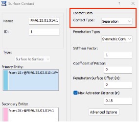
So, I'm going to go ahead and edit Contact 1.
10:12
So, right click and go to "Edit".
10:14
I can see the contact type is bonded.
10:17
If I hit the drop-down menu here, I can look at these other contact types.
10:21
Now, separation as we've gone through before, allows for sliding and separation bonded welds them together, sliding allows for sliding in plane,
10:32
but it would act like it's bonded in tension and compression.
10:35
I don't really want any bond between the two parts.
10:38
So, the best option here is going to be a separation contact that prevents the two parts from penetrating or overlapping one another,
10:46
but it will allow them to slide and rotate freely.
10:48
So, activate separation for that contact type and then I'll select "Ok".
10:55
I'm going to edit Contact 2.
10:59
Same thing here. I'm going to change it to separation and select "Ok".
11:03
So, now Contact 1 and 2, the icon has changed to a separation, contact.
11:08
The other four will remain bonded, which is what I want.
11:11
And this will give me a more accurate result when I go to solve because I'm going to allow for some more degrees of freedom to be available.
11:18
So, I'll go ahead and save this model with the contact updates,
11:22
and I'll solve it again and then I'll be able to compare the result for stress and displacement.
11:27
So, I'll select "Run".
11:32
So, after solving a second time I'll notice that the stresses and displacements look most of the same.
11:38
If I look at the area where I'm seeing the maximum stress, it has moved slightly.
11:44
It's now in between those two parts that are bonded together, but I still have similar hot spots around that area.
11:50
If I go to displacement, I should be seeing less than a thousandth of an inch and the displacement is very similar.
11:57
So, that's good. I haven't changed the model significantly.
11:59
But what I am allowing for is if I go to Contact 1 here,
12:04
and I look at the contact reactions once again, you'll notice now there's only a couple pound force of reaction force.
12:10
I'm not really seeing a significant amount of reaction in the Y or the Z where I was seeing about 100 and 60 in the Y and 900 in the Z before.
12:19
Now, there's not much of an interaction there that means that the load is being transferred to the correct components.
12:26
And I'm not artificially stiffening the model with an artificial bonded contact.
12:32
So, this is going to be a much more reliable and accurate contact set,
12:36
and I'm now ready to run a convergence study to analyze these results even further.