00:04
Now let's have a look at layouts.
00:06
A factory layout is basically the container of all your factory related spatial representation.
00:12
They allow you to place assets but also references of the building context.
00:15
For example, you can use one or more existing DWGs in form of an underlay as a reference for positioning.
00:22
Larger layouts or if multiple users need to work on the same layout and parallel for instance,
00:27
can be broken up into so called sub-layouts.
00:30
Inventor's any CAD functionality can be used to reference building context coming
00:34
for example in the form of a Revit project file,
00:37
the layout with all their content is also the file
00:39
that you would synchronize by directionally between the involved tools.
00:43
Let's see how that looks in action.
00:46
Here we are looking at the master layout of a digital factory model created via factory design utilities.
00:52
It consists of different production lines and office space as well as some reference DWG underlays.
00:57
We would merely like to modify the setup of one of the production lines,
01:01
so we opened its sub-layout in order to do so.
01:10
the first changes we would like to apply in birds eye view for convenience,
01:13
so we trigger the synchronization to AutoCAD via the dedicated command in the ribbon panel.
01:18
The layout gets opened automatically with an AutoCAD
01:21
and updated appropriately reflect the same state as we saw inside of inventor.
01:27
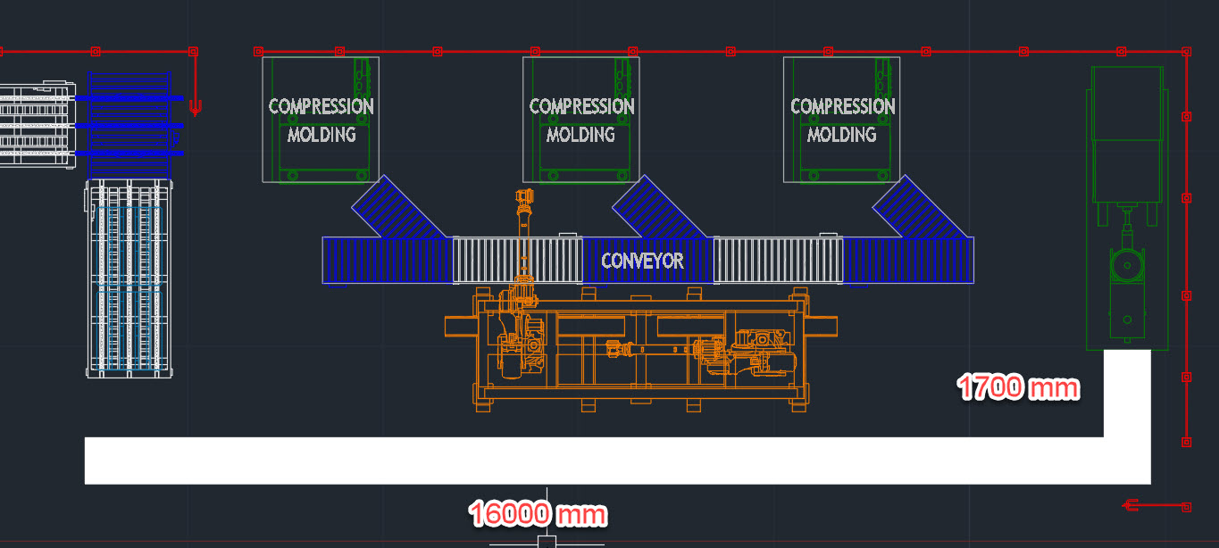
Now, we can begin with our modifications.
01:29
We would like to add a conveyor system from one machine through the whole production area.
01:33
Let's say the customer requested this to reduce time spent by factory workers to move the product to packaging.
01:39
We therefore access our asset library on the right hand panel and brought for the correct conveyor.
01:44
In this case we also leverage some built in automation in form of our configured as chain asset.
01:50
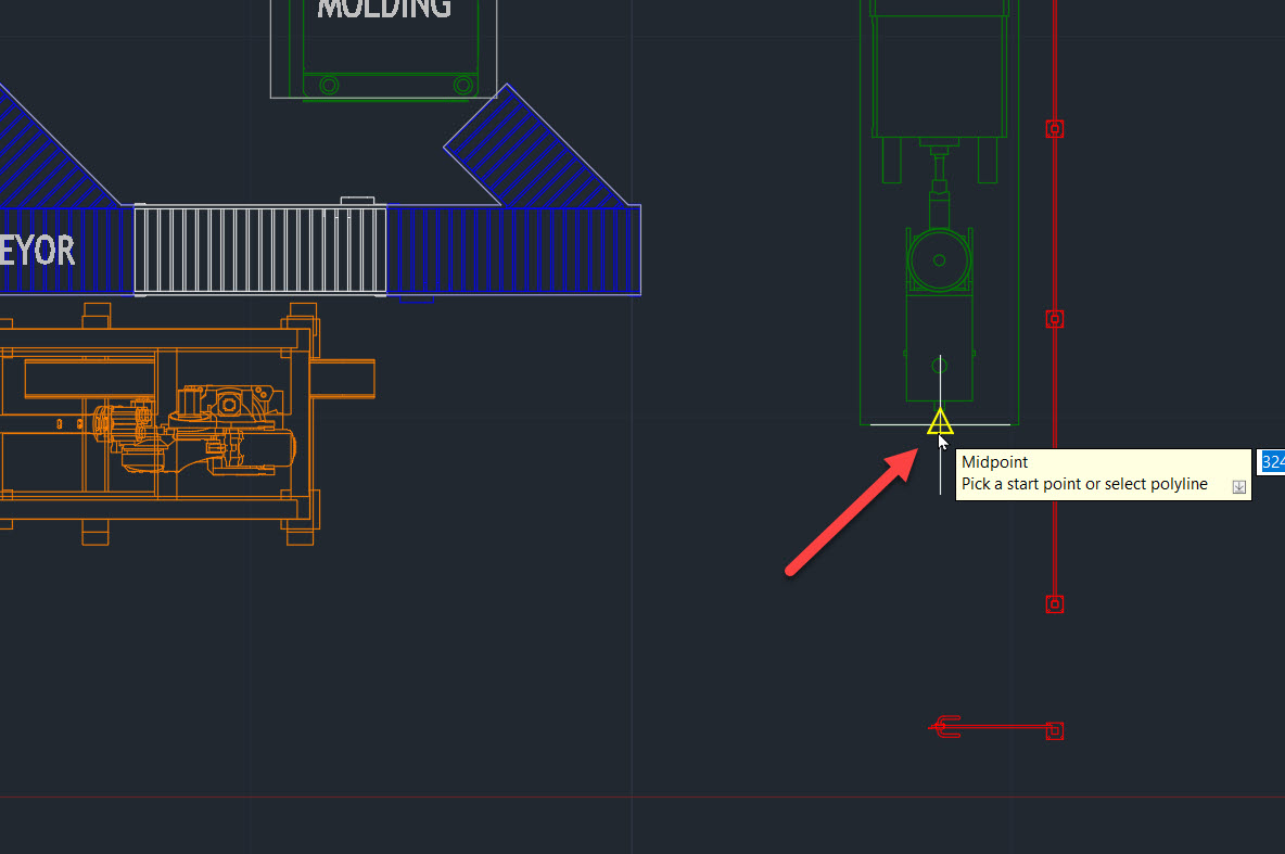
As we drop polyline representing the middle of the route Our conveyor should run along
01:54
and trigger its conversion to an asset chain via the ribbon command.
01:58
Instances of the asset are placed fully automatically connected to each other
02:02
and visually represented within the layout.
02:06
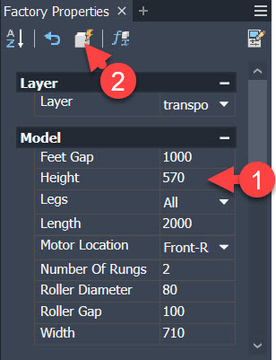
After confirming that the positioning and dimensions are correct.
02:10
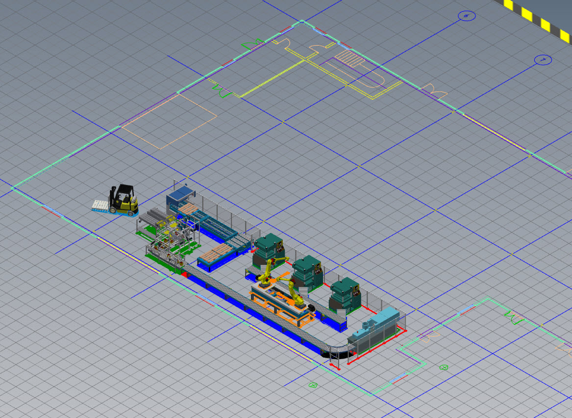
After population, we can then synchronize it back to inventor in order to review our updates in 3D space.
02:27
The 3D geometric representation is fetched from the factory assets file and populated within the 3D context as well.
02:35
First the 2D representation is updated and then the layer is populated with the associated 3D models.
02:41
You can see the different instances of the conveyors also being added in the model browser.
02:45
To keep things organized,
02:46
we assign them to the correct layer and simply move them to the dedicated folder that we created prior
02:51
or have setup within the layout template.
02:55
Now we unfortunately forgot to also add the receiving packing machine when we were in AutoCAD,
03:00
but not to worry as mentioned the same drag and drop mechanism to place assets is available inside inventor.
03:05
Again we browse to the library and start the placement by double clicking on the desired piece of equipment.
03:11
Note that as we move the preview of your assets to review,
03:14
the connectors that are available to connect to start reacting to each other,
03:18
making it easy to correctly align our packing machine.
03:23
we can exit out of the placement mode via right click done and tidy up the model browser again.
03:31
To close the loop with the rest of the team,
03:32
we save the changes and will get a notification within our Master layout
03:38
that there have been some updates to one of the sub-layouts.
03:41
Upon refreshing, we will see all the updates also reflected in the full digital factory
03:46
and we are ready for checking it in the modified files into our data management system
03:50
for other colleagues to be able to consume them.