00:03
Let's place a bolted connection and the holes associated with the fastener into the design,
00:10
will generate projected views of the bolts without having to draw them,
00:14
and then add a spring in additional fasteners without having to use any cleanup tools for the geometry that's already in the drawing.
00:22
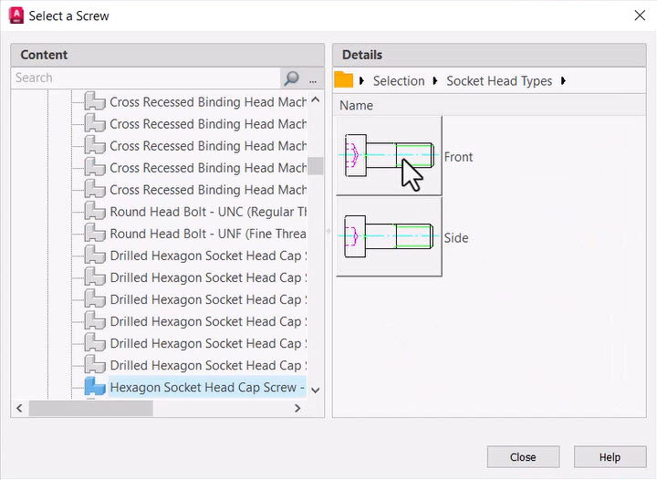
It's easy to find libraries of fasteners and even download specialized ones from the web.
00:27
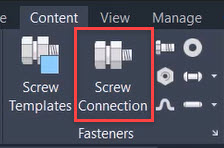
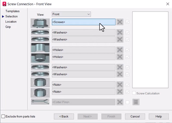
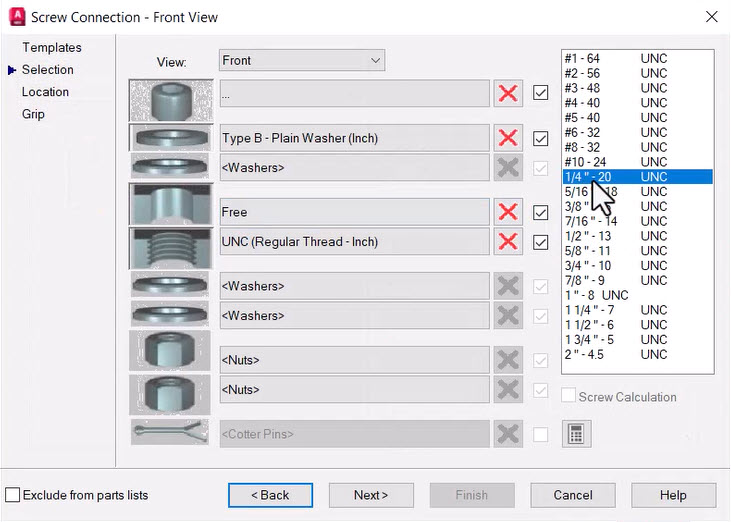
The Bolted Connection tool inside of AutoCAD mechanical allows you to select a series of fasteners,
00:33
whether they're bolts or screws, washers,
00:36
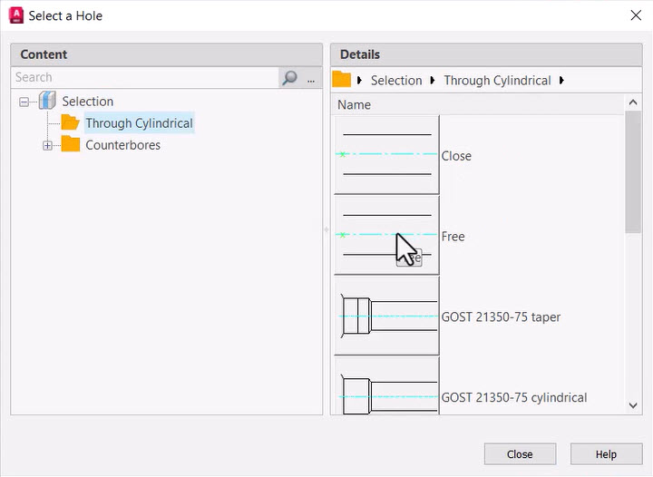
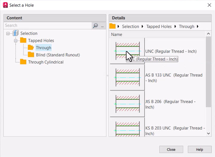
and then choose what type of holes they will pass through as they go through elements of the drawing.
00:43
You have a broad selection of standards and within those standards, a broad selection of the individual fasteners to choose from.
01:04
Once you've selected the bolt stack, you can even save it to a library if you use that combination of fasteners frequently.
01:27
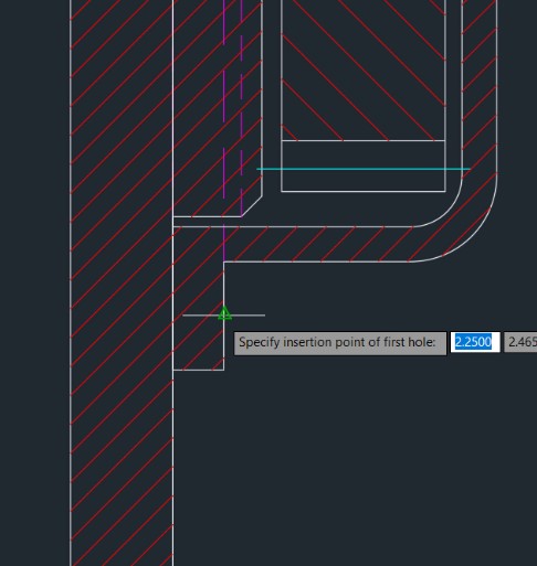
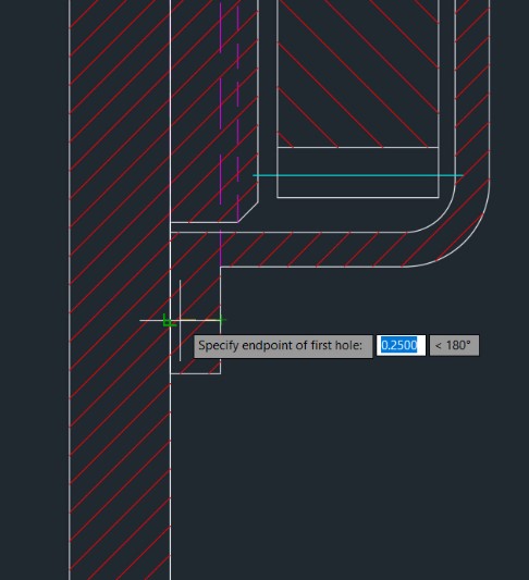
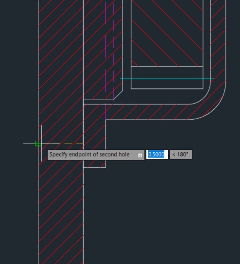
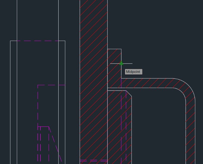
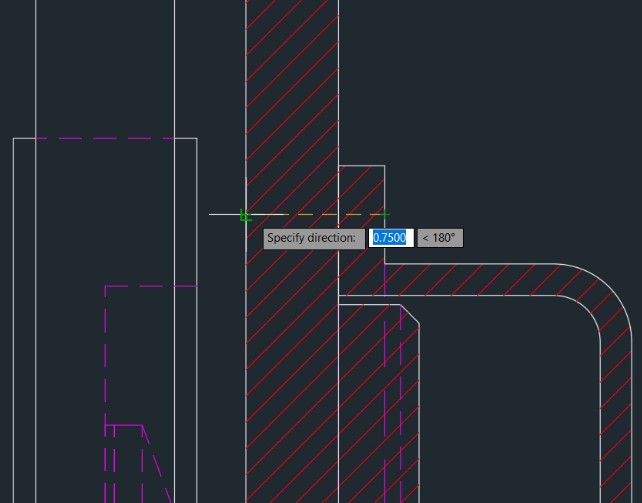
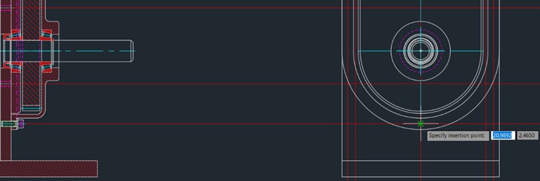
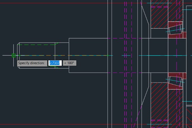
Then selecting the location, you want to place the fastener, you'll be choosing where the holes will pass through.
01:34
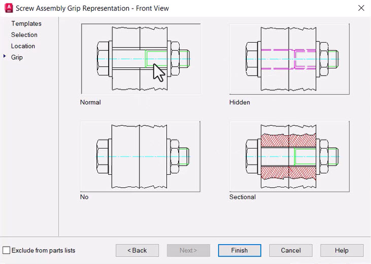
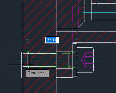
After setting the location values,
01:36
you choose how you want the Bolted Connection to appear and it will update the rest of the drawing to follow suit.
01:55
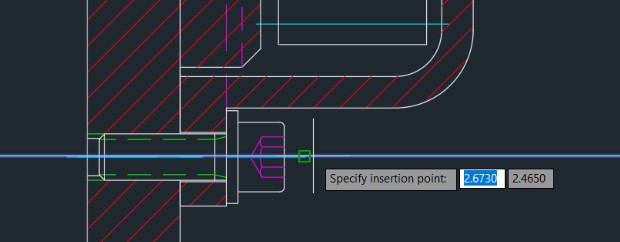
If you need more than one instance of this Bolted Connection,
01:58
you can use the Power Copy tool to select the object,
02:03
and place another instance of it into the model without having to reselect all of the various options.
02:09
Simply place it and it takes care of all the cleanup for you.
02:41
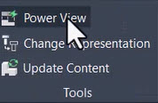
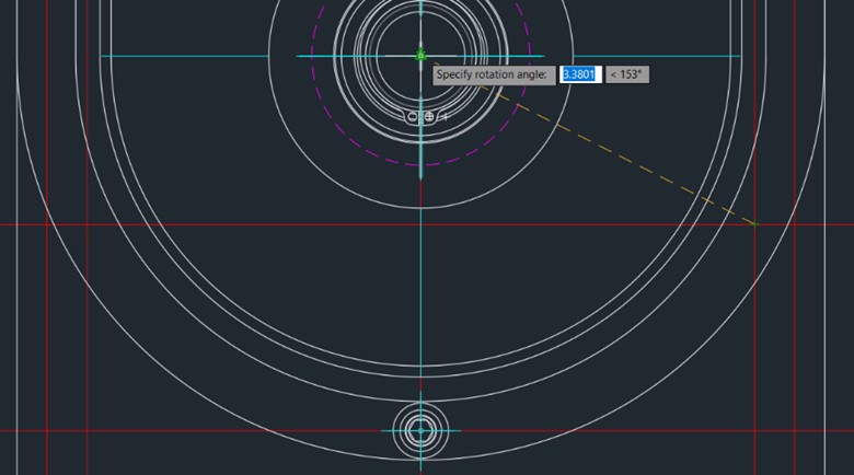
Now that we have one set of Bolted Connections, let's go ahead and place a Power View of the Bolted Connection.
02:48
A Power View allows you to generate an alternate view of the connection.
02:52
So we'll put a top view of the bolt in place.
02:55
Then we'll use Power Copy again to replicate that.
03:11
Including the ability to follow standard drafting practice and orient the new Bolted Connection around the axis.
03:27
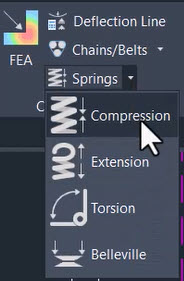
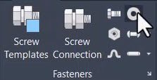
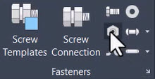
There are many other types of standard hardware built into AutoCAD Mechanical as well.
03:33
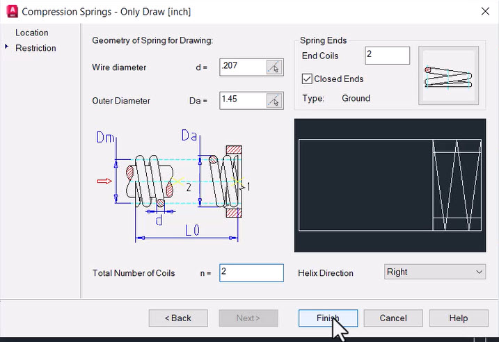
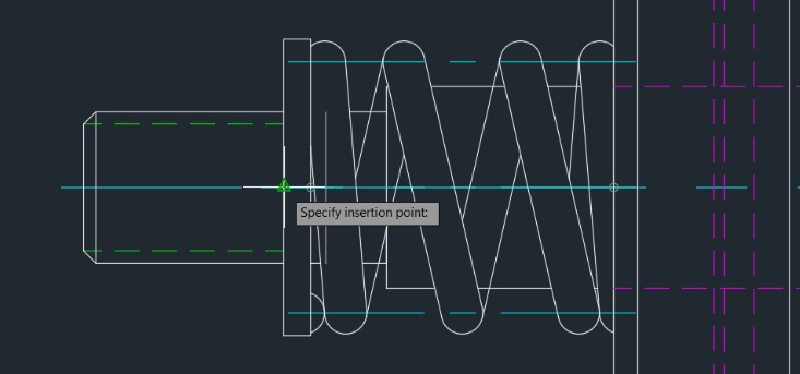
For example, you can place many types of springs.
03:36
You can calculate the spring.
03:38
You can use standard predefined springs from catalogs, or you can generate your own type of spring,
03:45
or you just simply need to represent the spring on the screen.
04:04
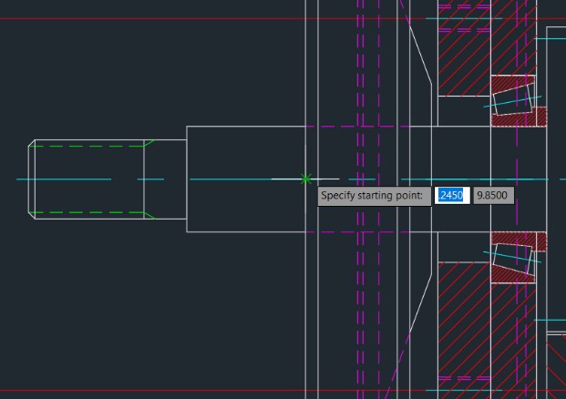
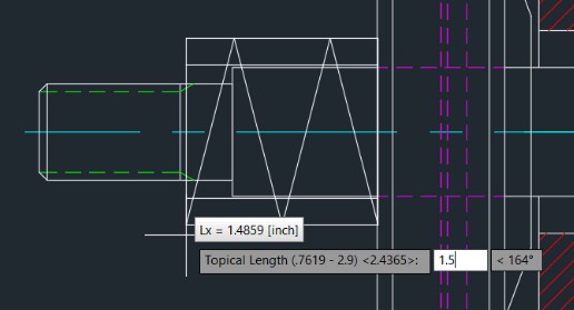
You choose the style you want, set the size attributes,
04:19
and place it into the drawing with automatic cleanup of any of the entities that spring would be wrapped around.
04:43
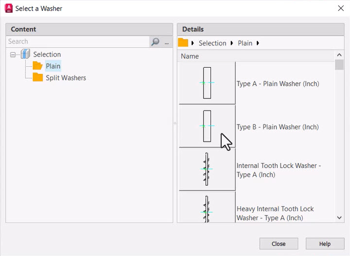
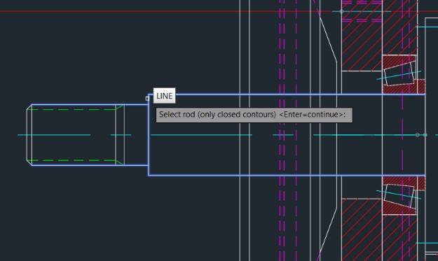
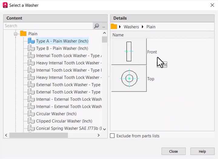
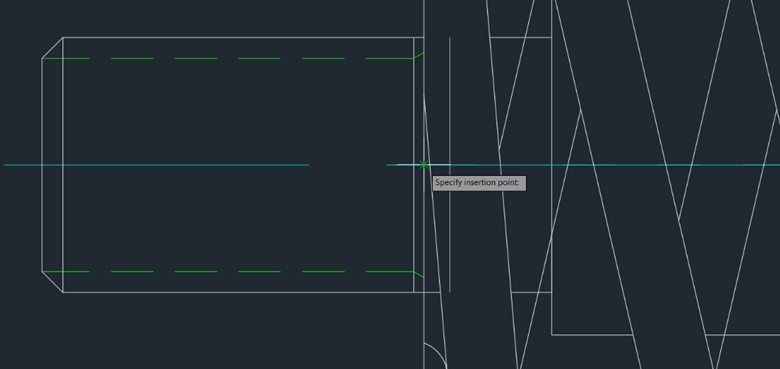
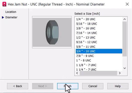
Once the spring is in place, you can go back to the Libraries and Select a Washer, choosing standard size options.
05:24
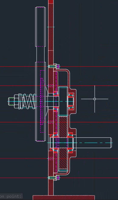
And place a Nut to retain it all.
05:28
And once again, all of this is done without having to do any cleanup of objects that were already in the drawing.
05:49
And having the intelligence built into AutoCAD Mechanical to understand that these are not just lines and arcs,
05:54
they are real objects that have relationships to one another.