00:04
Let's use the standard belt to define the required pulleys.
00:08
Calculate the proper location of an idler based on the belt length and insert a portion of the detailed belt in a drawing.
00:16
Not all standardized components are as convenient as bearings or fasteners that come in uniform sizes.
00:23
Objects like belts come in specific length, but you have to be able to make them fit in your design.
00:31
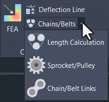
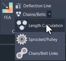
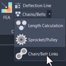
With the chain and belt tools, an AutoCAD Mechanical,
00:35
we can place sprockets for chains or pulleys for belts that have their geometry defined by the type of chain or belt that will be applied.
00:48
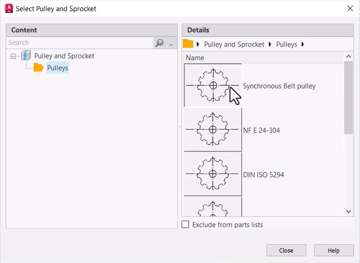
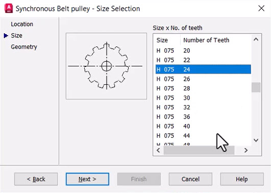
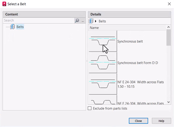
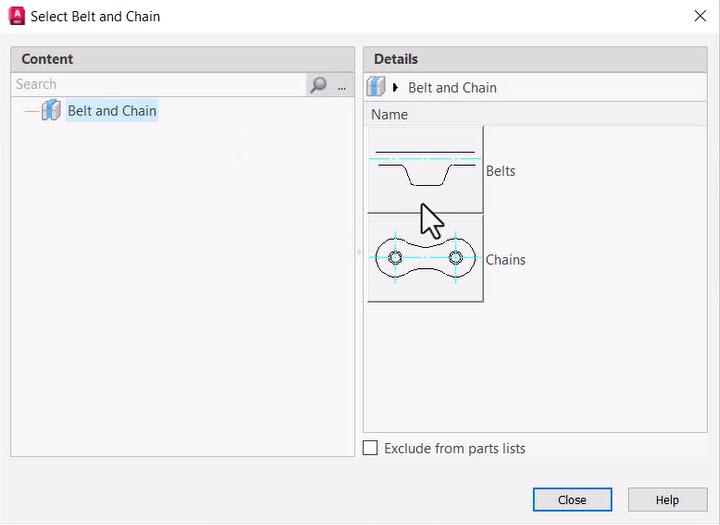
As you would expect from AutoCAD mechanical, there are a broad variety of standards available to you.
00:54
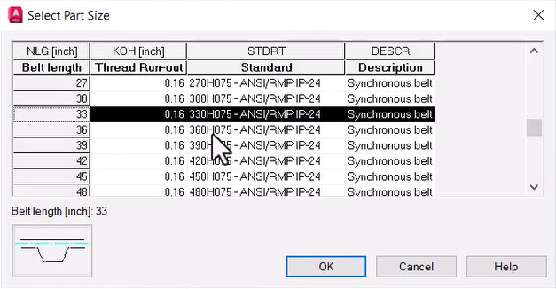
You'll need to select the standard and the number of teeth that you need.
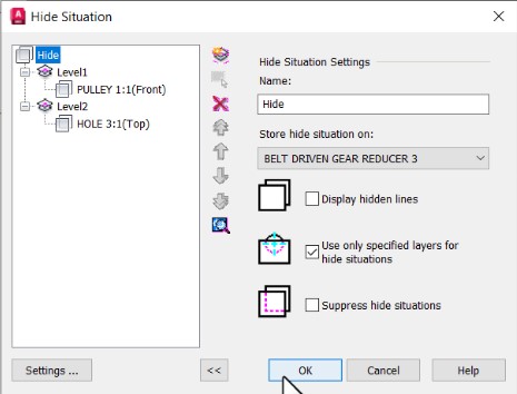
00:58
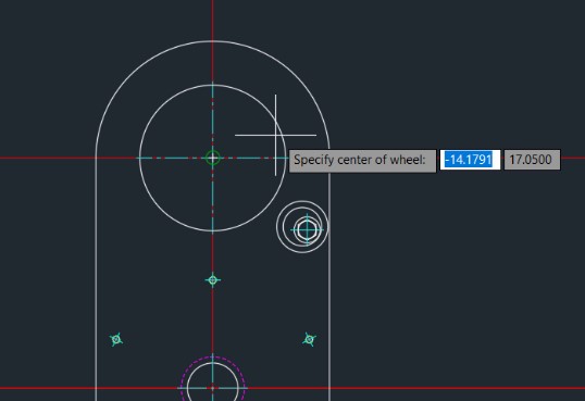
Placing it into the drawing, you'll be offered an opportunity to hide any objects or create hidden lines,
01:05
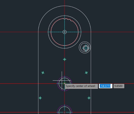
then we'll place the other sprocket.
01:08
Right now, of course, we're not exactly sure about how the spacing will work with the number of teeth that we need for this belt.
01:15
You can also do a function for calculating the number of teeth based on the sprocket spacing you need.
01:28
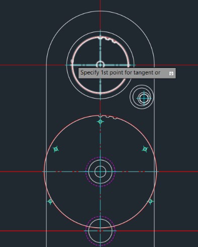
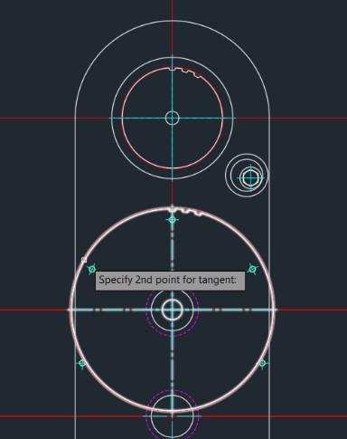
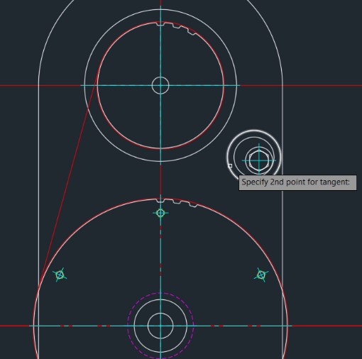
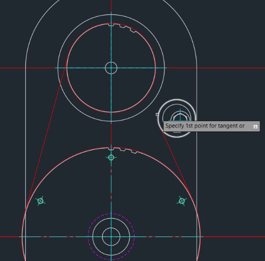
Once the pulleys are in place, AutoCAD mechanical makes it easy to define the path of the belt.
01:34
For this drawing, we have the two pulleys, but we also have an idler that's put in place.
01:47
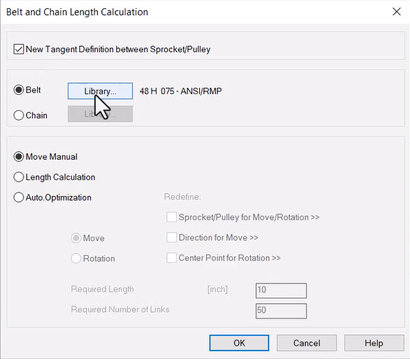
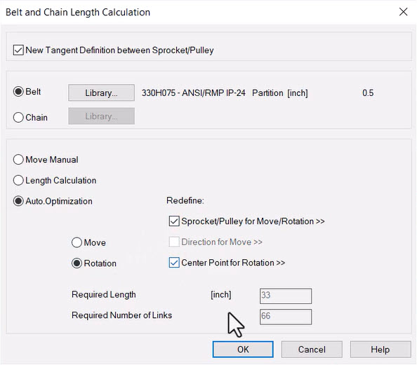
Selecting the belt with the number of teeth and the length that we need,
01:52
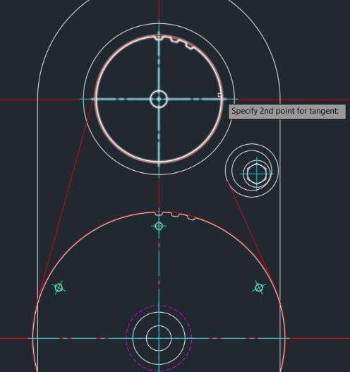
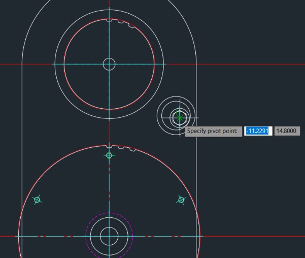
We'll tell it to automatically calculate how the idler needs to be positioned for this belt to fit in the design.
02:16
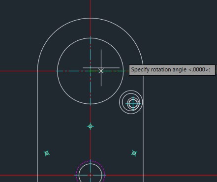
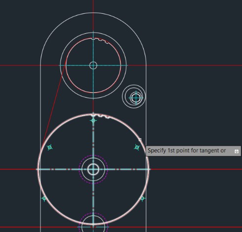
After the path has been established,
02:18
you can set the objects that need to be rotated and the center point and it will adjust the idler to fit a belt size that you can purchase.
02:31
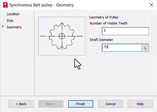
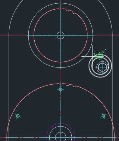
And returning more to the craft of drafting,
02:33
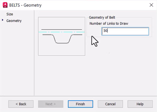
we want to make it easier for people to understand what type of object is in the drawing.
02:42
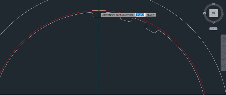
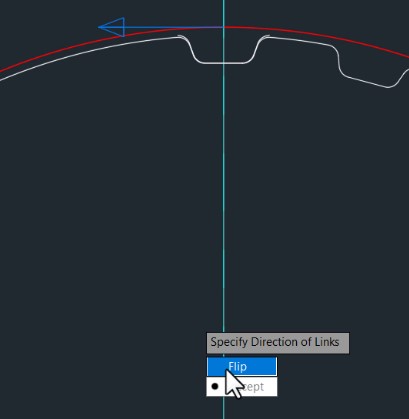
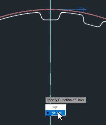
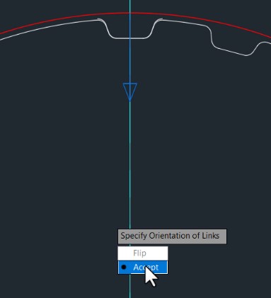
Selecting a position to start and establishing a number of teeth you want to add to the belt, it will go ahead and draw this in.
02:49
Skipping the process of having to create any sort of block for the belt and using an array tool to try and go around this complex curvature.
03:05
AutoCAD Mechanical does a phenomenal job of combining the convenience of being able to leverage standards,
03:10
and the drafting tools you need to present these objects in a way that people can easily understand.