Step-by-step guide
Once joints are added to an assembly in Fusion, implementing joint limits, motion links, contact sets, and motion studies can help to create a more realistic and functional model.
The design in this example has joints configured to create a vise on a hinge:
- A slider joint connects the sliding jaw with the fixture.
- A revolute joint enables a handle to rotate a screw through the sliding jaw.
- Another revolute joint is used as a hinge for the entire device.
When dragging these joints, the sliding jaw can pass through the fixtures, and the handle does not cause the sliding jaw to move. These issues can be resolved using a combination of joint tools.
Limit the movement of the jaw slider joint
Use the Edit Joint Limits tool to limit the sliding jaw movement:
- In the Browser, expand the Joints folder and select the sliding joint.
- Right-click the sliding joint to access and review the available joint tools: Drive Joints, Edit Joint, Edit Motion Limits, Lock Motion, Suppress, Animate Joint, and Animate Joint Relationships.
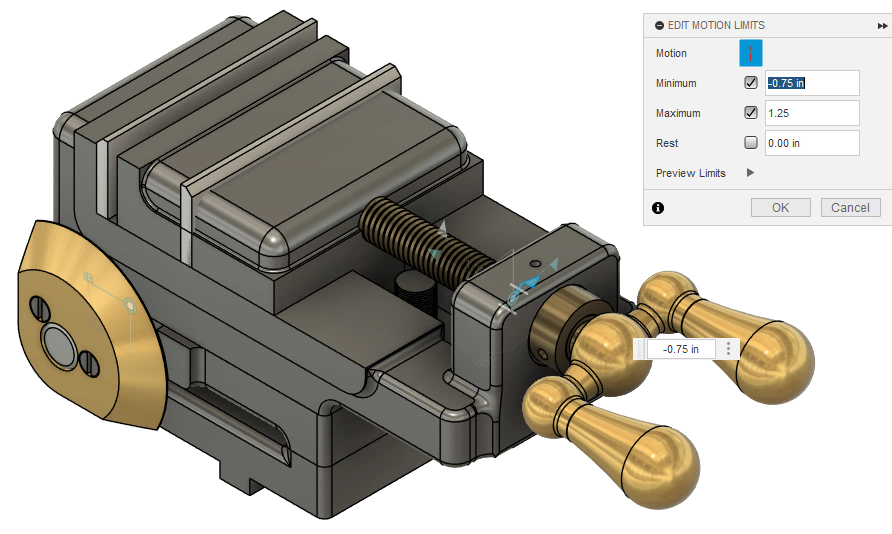
- Select Edit Motion Limits.
- In the Edit Motion Limits dialog box, select Minimum and Maximum.
- Set the Minimum to -0.75 inches and the Maximum to 1.25 inches.
Flags show on the canvas to indicate that the limits are active.
- Move the sliding jaw to see that it now stops at each end of the vise.
Note that joint limits only affect the specified joint and do not consider related components.
Link the motion of the handle to the sliding jaw
For the assembly to work properly, turning the handle must move the sliding jaw of the vise. Create this relationship by adding a motion link between the revolute joint and the slider joint. Linking these joints enables a ratio of rotation-to-motion to be established.
- On the toolbar, click Assemble > Motion Link.
- If a notification asks whether to revert or capture the position, choose Revert Position.
- In the Motion Link dialog box, click Select.
- In the Browser, select the relevant joints, Slider 42 and Revolute 16.
An automatic animation shows the handle and sliding jaw moving together.
- For Slider 42, set the motion to Slide Z and the Distance to 0.394 inches.
- For Revolute 16, set the motion to Rotate Z and the Angle to 360 degrees.
For each complete rotation of the handle, the slider will move 0.394 inches in or out. This setup simulates a gear ratio without relying on computationally heavy contact sets.
- Click OK to save the link. This adds it to the Joints folder.
- Rotate the handle to see that now, the slider moves along with it.
Refine the accuracy of the jaw slider joint limits
Because the maximum limit previously set for the slider joint was approximate, the jaw plates pass through each other at the fully closed extent. Use a contact set to make the maximum limit precise.
- Click Assemble > Enable Contact Sets.
- In the Browser, right-click Contact Sets and select New Contact Set.
- Select the two jaw plate components.
- Click OK.
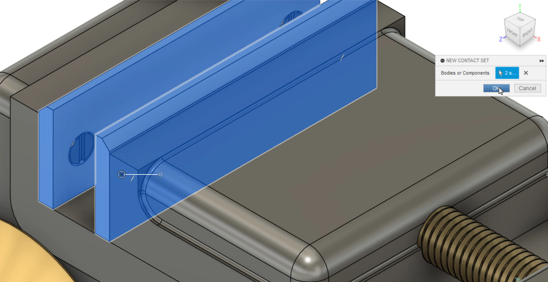
The movable jaw now slides until the two jaw plates make contact; then it stops.
Replace the contact set with accurate joint limits
Contact sets are computationally intensive and may slow down your system. In this example, the contact set created previously can be used to determine the exact maximum distance for the jaw slider. Then, after using this value to edit the slider joint limits, the contact set can be removed.
- Make sure that the two jaw plates are in contact, with the jaw slider at its maximum distance.
- On the canvas, double-click the slider joint to see that the current offset value is 1.216 inches.
- Press Esc to clear the selection.
- In the Browser, right-click Slider 42 and select Edit Motion Limits.
- In the Edition Motion Limits dialog box, set the Maximum value to 1.216 inches.
- Click OK.
The contact set can now be deleted or suppressed.
- In this case, it is no longer needed, so right-click it and select Delete.
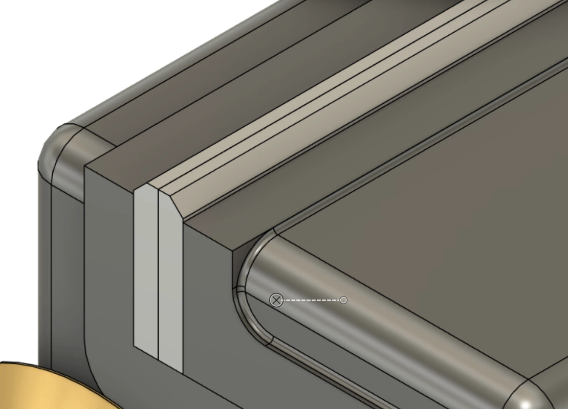
- Slide the jaw back and forth to see that the plates contact each other but do not overlap.
Study the motion of the vise assembly
Finally, explore the concept of motion studies.
To use a joint in a motion study, first, it needs to be unlocked.
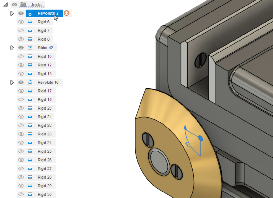
- Right-click the Revolute 2 joint and select Unlock Motion.
To build the motion study:
- Click Assemble > Motion Study.
- When prompted, select the Revolute 2 joint.
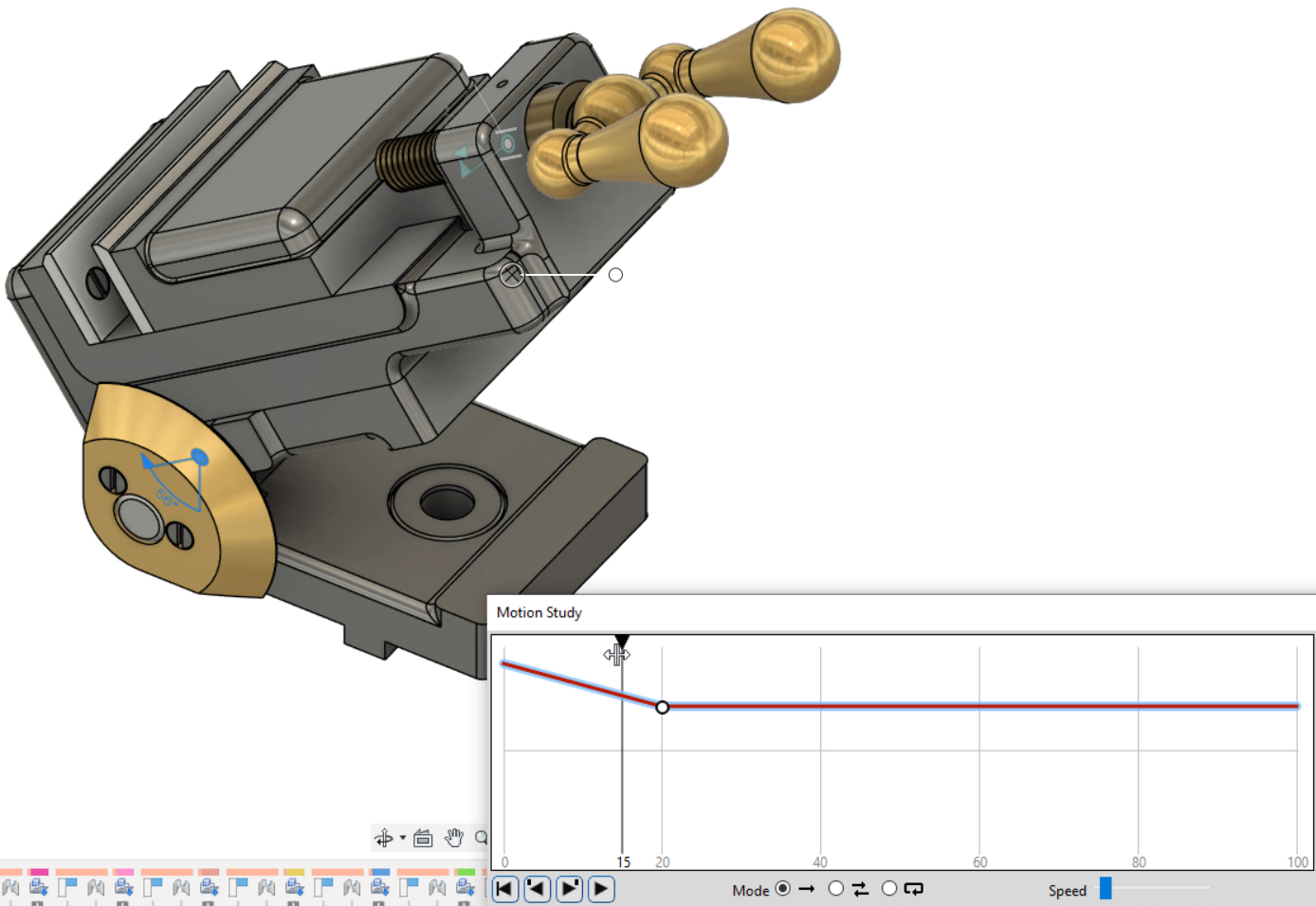
Now, steps can be added and joint values defined at each step to simulate motion over time.
- In the Motion Study dialog box, click to place a keyframe at time step 20.
- Set the Angle to 45 degrees.
- Press Enter. The angle of the vise changes.
- Drag the playhead back and forth to simulate the motion of this joint.
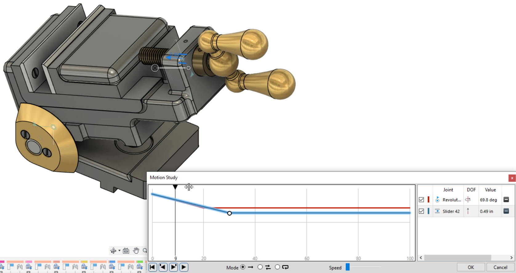
Motion studies also enable the analysis of multiple joints interacting simultaneously:
- To add a joint, in the Browser, select the Slider 42 joint.
- In the Motion Study dialog box, click at time step 30 to add a keyframe to the slider joint.
- Set the Distance to 0.2.
- Press Enter. The jaws open.
- Move the playhead back and forth to see the jaws moving and the vise angle changing.
- Use the controls to set the playback Speed and Mode for the study, as needed.
- Click OK.
The motion study is saved in the Browser for future reference. Unlike using the Animate Joint tool, motion studies consider all related joints, offering deeper insights into the overall motion.


