Here at Fusion 360, we’re passionate about enabling electronics engineers to easily design PCBs with high-speed components. The Fusion 360 Signal Integrity Extension helps improve product compliance and performance, reduce costly physical PCB testing and prototyping, and accelerate high-speed PCB development
There are many rules of thumb to follow when laying out a PCB with high-speed components. Let’s look at some of them, explore why it makes sense to follow them, and determine when it’s okay to deviate from them.
1. Keep your traces short and straight whenever possible
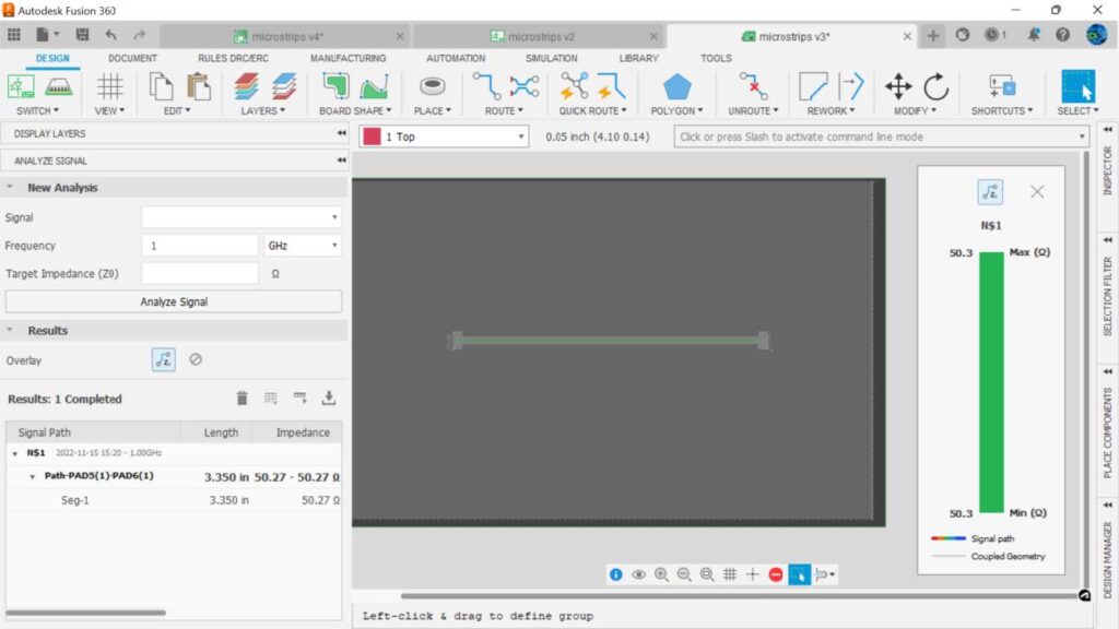
Everyone agrees that this rule of thumb is a gold standard. Short straight traces have the least time delay and maintain a consistent impedance. PCB layout simulation software like the Fusion 360 Signal Integrity Extension can calculate the impedance of a trace all along its length, letting you know if and where discontinuities are.
With the Fusion 360 Signal Integrity Extension, we can see that a straight trace exhibits a constant impedance along its length.
2. Don’t use 90° corners (it’s okay, you can use them)
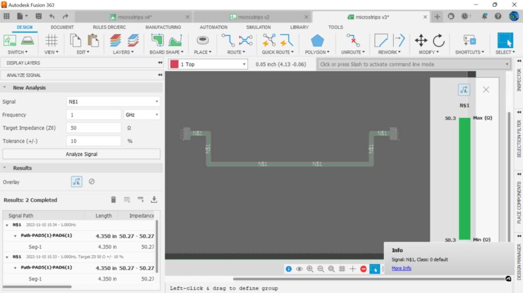
This is common rule that is stated almost as often as it is refuted. The common thread to this rule is that 90° corners cause an impedance discontinuity, that is, a change in impedance occurs when you have a 90° corner on a straight trace. Well, that’s not the case unless you are working in sub-mm bands. Notice this trace routed with 90° bends maintains a constant impedance.
What does matter when routing traces in high speed designs is containing the fields. It’s the reason we use a ground plane underneath a trace. Look at what happens to the microstrip if we snake the trace back and forth close to itself.
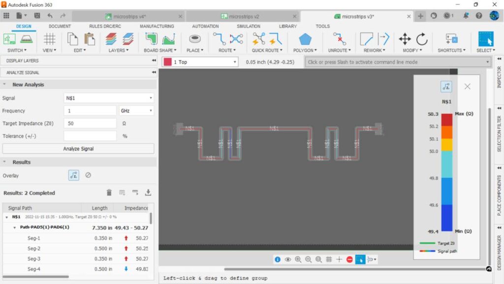
We see that the impedance is now varying. Yes, not by much, but it is still changing because fields are now overlapping.
Neighbouring traces play a role too in determining impedance.
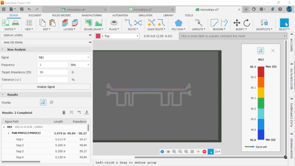
Notice that where the fields can overlap because they are close to each other, an impedance change occurs.
Notice too, that the closer a trace is to a neighbouring trace, the greater the impedance discontinuity.
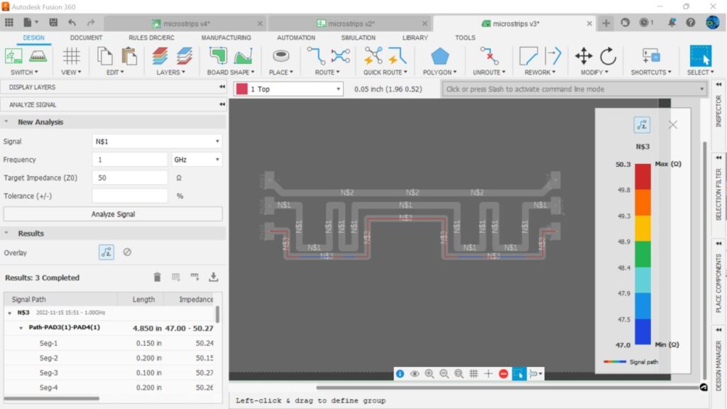
So, 90° corners play no role in impedance discontinuities. What matters is the neighboring fields that are close enough to overlap – that’s what will impact impedance.
So, is there any reason to follow the rule of no 90° bends? Yes, if you are designing high voltage PCBs any sharp corner will concentrate electric fields and may result in flashover arcs occurring. Another advantage of using 45° corners can be shorter traces and smaller loop areas resulting in less EMI (Electro Magnetic Interference) and faster signal arrival.
Speaking of signal arrival, let’s look at the importance of length matching.
3. Length-match high-speed signals to avoid mismatches in signal arrival time
It’s important that the length of trace match when routing high-speed signals as mismatches in length mean mismatches in signal arrival time. Consider a high-speed clock signal, and it’s associated data.

From: Difference Between Serial Communication Function With and Without Clock | Renesas Customer Hub.
The rising edge of this clock determines whether the data to be read is a zero or one. With high-speed signals the time it takes for the signal to travel down the trace (called the propagation delay) can play a role in whether the signal will be correctly read. Examine the situation below where the bottom clock trace is longer than the top data trace.

In this case, the clock signal is delayed much more than the serial data signal, and instead of the receiver reading 01101 it will incorrectly “see” 11010. It’s important that high-speed signals be length matched. The SI extension in Fusion 360 electronics calculates propagation delays in traces, making it easy to see if timing of signals will be a problem.
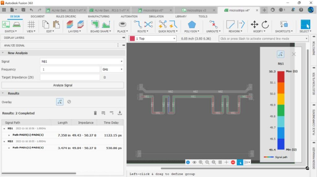
Here we can see that the difference in propagation time between the two traces is 591.29 ps. If our clock frequency pulse on time begins to approach the difference in propagation time between the two lines, we will have errors in the data read.
Consider the case where the difference in propagation times is less than the pulse on time.

We can see above that data sent = the data received.
However, the more the difference in arrival time approaches the pulse on time, the more likely errors will occur.

This difference in time between data and clock is called Clock Skew. Which leads us to our next rule of thumb.
4. Keep clock skew less than 1/10 of clock period
We can see from the example above this rule of thumb keeps the clock edges well away from the data transition zones. If our clock and data signals have a greater difference than 1/10 of the clock period we need to lengthen the faster signal.
5. Lengthen traces to equalize timing delays
There are several ways to lengthen a trace so that timing differences are brought within specification. If the mismatch in length is small it can be lengthened by rerouting the trace to make it slightly longer. The SI tool in Fusion 360 Electronics will display the propagation delay of a trace and you can decide if you need to tweak the length or lengthen it using meandering.
6. Follow the 4X rule when meandering
Meandering means routing the trace back and forth to lengthen it. Consider the PCB shown and notice that the bottom trace is much shorter and is significantly faster than the top trace.
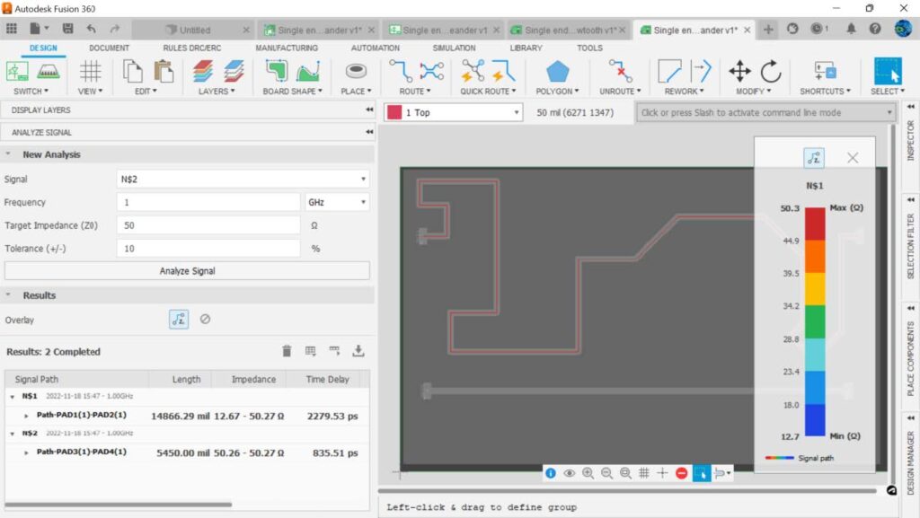
Meandering the bottom trace results in longer lengths and propagation delays that can be within specification. Fusion 360 Electronics allows you to meander both single-ended signals and differential signals.
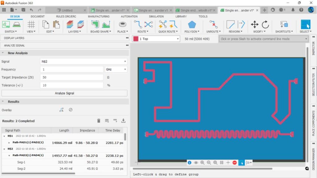
When meandering, layout designers often follow the 4X rule: Keep the distance between bends 4X the trace width as it will minimize impedance discontinuities. Let’s look at the impedance of our trace in this example.
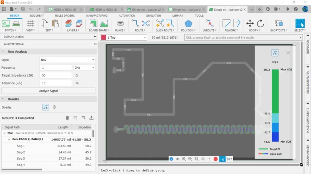
There is a lot of discontinuity between adjacent trace sections. Again, it’s the electric fields overlapping each other. Look what happens when we make the spacing 4X the trace width. The impedance now becomes consistent.
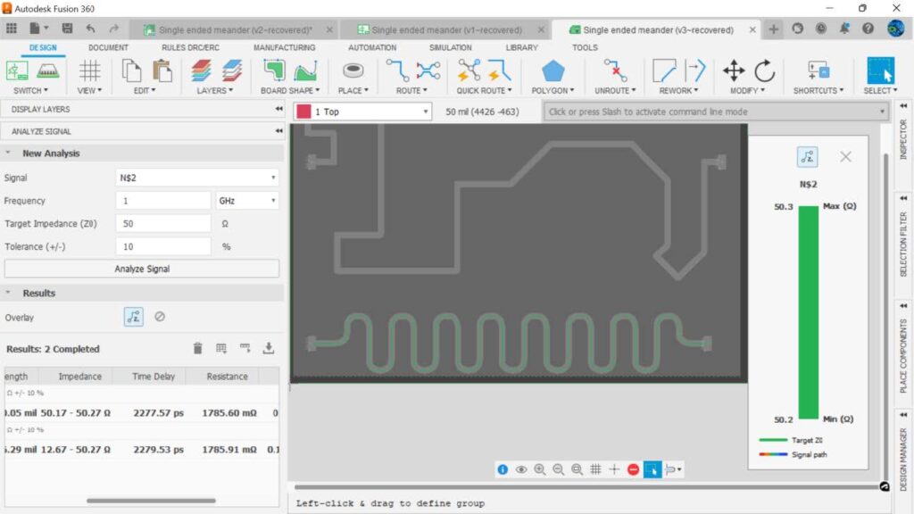
Differential pairs may also require lengthening but let’s wait until later when we discuss differential signals.
7. Follow the 3W rule for minimizing crosstalk
In the early days of telephony, you could hear your neighbors’ conversations if the wires in the cable carrying the conversation were side by side. Users and telephone engineers called this phenomenon “crosstalk”
Consider a conventional single-ended digital signal. The data consists of high and low voltages representing 0’s and 1’s.

However, nearby traces can couple unwanted noise onto the signal.

If the coupled noise (unwanted signal) from the aggressor signal is large enough the victim signal can be garbled so badly it is unrecognizable.

The 3W rule for crosstalk states that parallel traces should be at least 3W away from each other, measured from center to center of the trace, to minimize coupling between them, where W = width of your trace. Of course, more space is better especially as frequencies increase into the GHz region or if the lengths are excessively long. Note too, that the 3W rule assumes a ground plane on an adjacent layer as this constrains the electric field to a much smaller distance on either side of the trace.
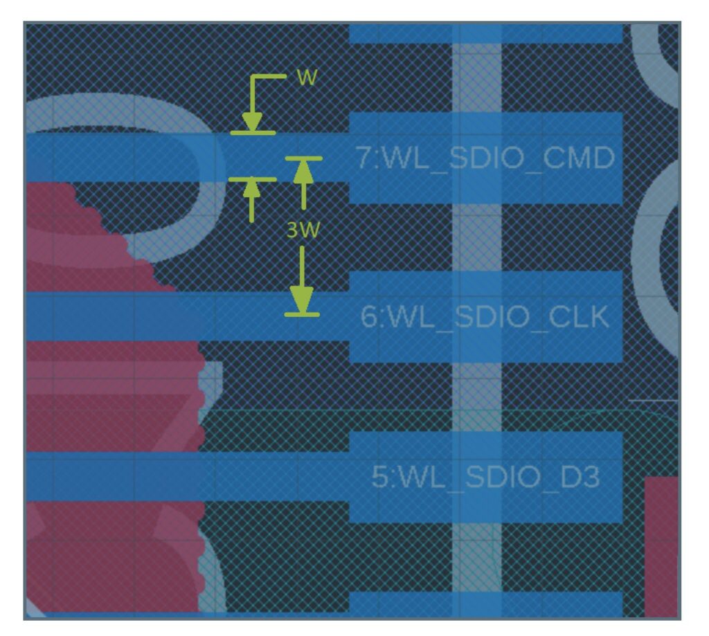
You can consider two adjacent traces as two traces that are capacitively coupled. A capacitor is just two plates separated by an insulator – exactly what two adjacent traces are with the insulator being the air between them. As with capacitors, the greater the distance between plates the lower the capacitance. The lower the capacitance, the smaller the coupled signal. Similarly, the longer the plates are, the greater the capacitance and the greater the coupled signal. So, strive to keep your traces short and far apart in high-speed design.
8. Follow the 8W spacing for differential clocks (or explore other rules)
Even greater spacing is needed for high-speed differential signals. This rule maintains the desired signal impedance. This 8W rule also applies to ground planes on the same layer. Consider the following USB differential pair:
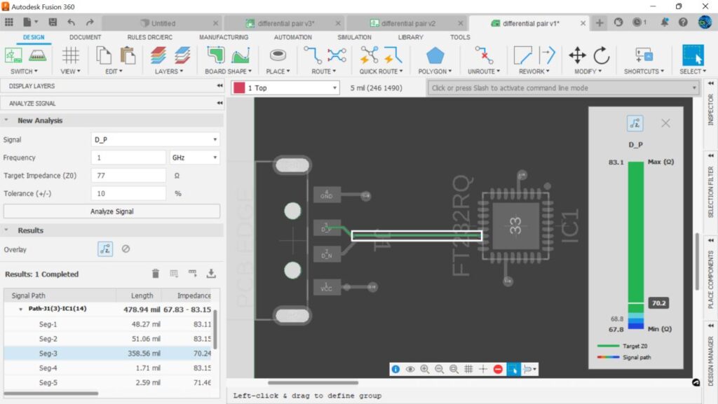
Most of the trace has a 70.2 Ω impedance. Look what happens to the impedance if we place a ground plane on the top layer that is close to our signal. Impedance of the line is almost entirely 61 Ω.
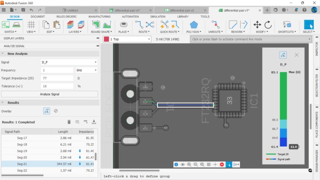
But, following our 8W rule and putting in and 80 mil spacing we get our previous impedance of 70.2 Ω.
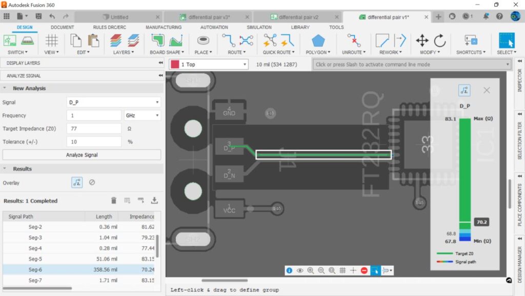
The 8W rule is conservative and some use 5W or even 3H, where H = the height of the dielectric between the ground layer and signal layer. With the SI extension, Fusion 360 Electronics can show you the calculated impedance values and help you determine the impact of crowding signals.
9. There isn’t a rule of thumb for differential pair length mismatches
We’ve mentioned differential signals a few times so far, so let’s look at them in more detail.
Differential signals are very common in high-speed communications standards such as HDMI, USB, LVDS to name just a few. That’s because they are resistant to noise. Let’s look at why they can reject noise.
Differential signals consist of two signals D+ (D_P) and D- (D_N). This pair of wires will have opposite polarities signals on them.

The receiving end of differential signals subtracts the negative signal from the positive signal resulting in a recovered signal that is twice the size of each signal alone.
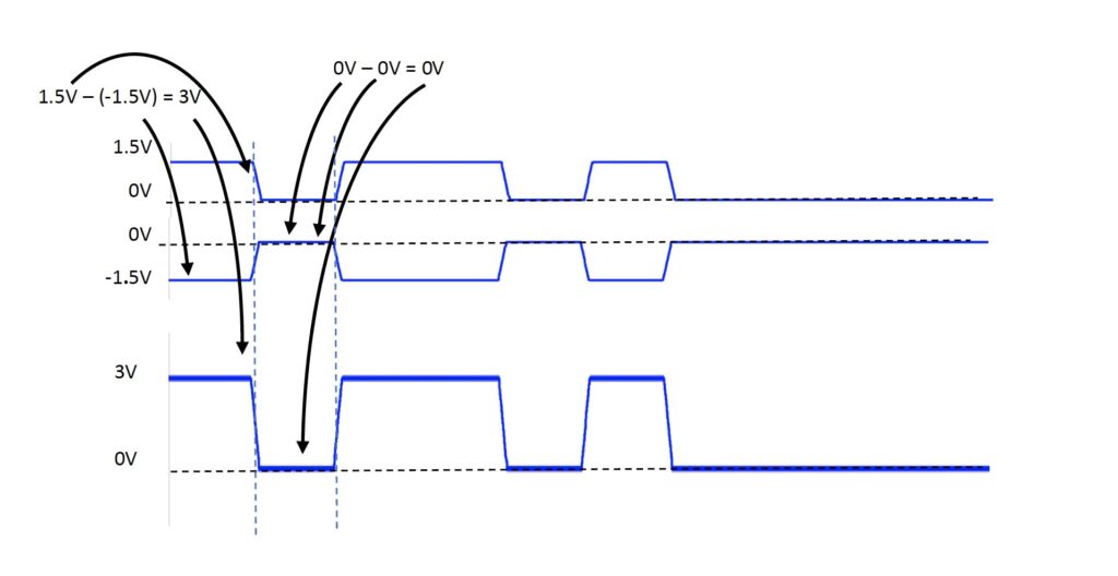
The real advantage of differential signals, as we said earlier, is that they reject noise. Consider a differential signal with an unwanted aggressor signal nearby that is coupling a signal to each differential line.
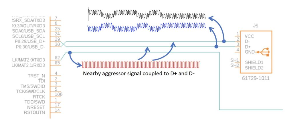
The resulting coupled signal will appear on each trace of the differential pair with the same polarity. That is:
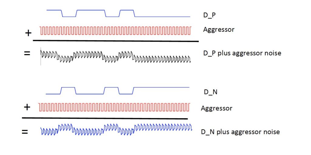
At the receiver, the two noisy signals are subtracted from each other, and we are left with two differential signals without any aggressor noise. That is,
(D_P + Aggressor) – (D_N – Aggressor) = D_P – D_N
And, from earlier, we know that D_P – D_N = a single signal twice as big. Graphically, it means:
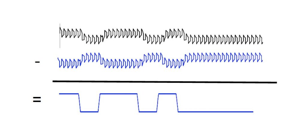
And the noise common to both signals is gone.
Differential signals are also sensitive to timing differences between the signal pairs. Consider the case below where one signal in the pair must travel a longer distance and therefore arrives later.

And D_P subtracted from D_N ends up looking like:

Maybe the receiver can decode the D_P – D_N correctly, maybe not. Which leads us to our next rule of thumb: there isn’t a rule of thumb for differential pair length mismatches.
High-speed signal specifications will identify the maximum mismatch in length your differential pairs can have. Adhere to the specification. Anything else may cause unwanted EMI or EMC issues.
10. Understand intra pair and inter pair skew
Intra-pair skew is the time difference between trace paths of a single differential pair. As shown above, a difference in timing can disrupt the signal so much it becomes unusable. The solution is to lengthen the shorter of the differential pairs.
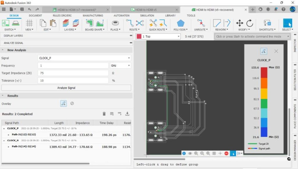
A “meander 1800 mil” command results in the clock lines being lengthened to 1800 mils (the length of the data lines).
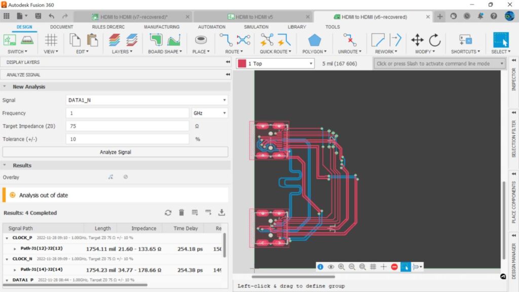
Notice that the meander also adjusted the lengths of the clock differential pair to minimize the inter-pair skew.
The Fusion 360 Signal Integrity Extension gives the layout designer the ability to simulate the impedance and propagation delay of traces. It’s possible to see the effects spacing, trace width, crowding of signals, and layer stack-up have on impedance-controlled lines. Rules of thumb can be verified, and insights provided can be used to determine whether a rule of thumb needs to be followed. With the Fusion 360 Signal Integrity Extension, designers can modify and adjust trace lengths and paths and improve the signal integrity of their PCBs and the quality of their designs.
Ready to get started with high-speed PCB design? Try the Fusion 360 Signal Integrity Extension for free today:
