Are you new to PCB design or a seasoned pro learning Autodesk Fusion 360? Either way, welcome! In this article, we’ll go over the basics of how to work with 3D PCB in Fusion 360. Throughout the article, we’ll answer 12 of the most commonly asked questions from our electronics community. Let’s get started.
1. How can I create a 3D PCB from a 2D PCB design?
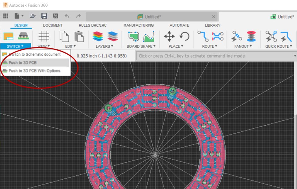
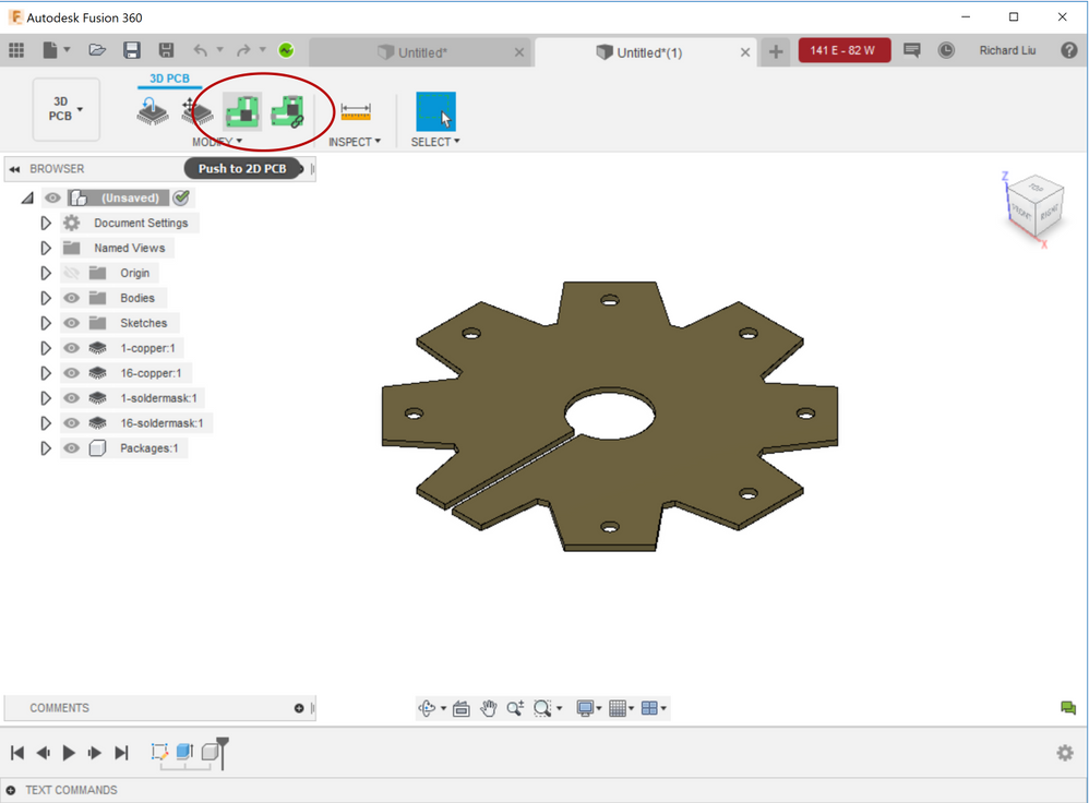
In the PCB Workspace, you can find the Push to 3D PCB and the Push to 3D PCB with Options commands. You can use either of them to create a 3D PCB. Push to 3D PCB is simply a shortcut to Push to 3D PCB with Options with default values. In a later update, we will combine them into one command.
2. How can I assign a 3D model to a package?
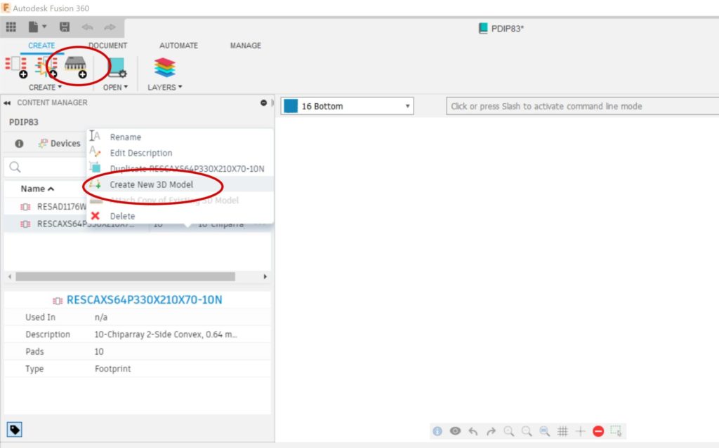
If you try to push your board to 3D PCB, you might find some parts appear as boxes in the 3D PCB. This can occur because there are no 3D packages created for those parts. Fusion 360 can still load 3D models from library.io, but now we recommend creating 3D packages in Fusion 360. This is done by using the Create New Package in the toolbar or the Create New 3D Model command in the context menu of the content manager in the Library Workspace.
3. What do the options in the Push to 3D PCB with Options Dialog mean?
There are some options to control how Fusion 360 will create your 3D PCB.
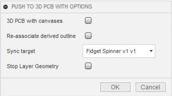
- 3D PCB with Canvases: When this option is checked, we won’t create 3D solids for the coppers. We just render them as canvases. As a result, it will take less time to create the 3D PCB. We recommend turning this option on if you want to view the 3D PCB quickly.
- Re-associate Derived Outline: This option is only valid if the board outline was from a derived sketch. In this case, if the outline is modified in the 2D PCB document, it’s not allowed to update the outline sketch in the 3D PCB. If the user does need to use the new outline from 2D PCB, they can check on this option and a new sketch outline will be created and so the association to the derived sketch will be broken.
- Stop Layer Geometry: When you check this option, we will create the 3D presentation of the solder mask in 3D PCB document. This option is off by default for performance’s consideration.
- Sync Target: this option only appears when you are editing in place (EIP) a 3D PCB. When pushing a 2D PCB to 3D PCB, we build a reference relationship between the 2D PCB and the 3D PCB documents. In EIP environment, a “new version” of the 3D PCB will be created in the EIP context. Updating the source 3D PCB won’t update the one inside EIP. In this case, the command needs to know which version of the 3D PCB to sync when run the command next time. The option is for users to select the target document to sync: the standalone 3D PCB, or that inside EIP context.
4. How can I create a 3D PCB before we have a 2D PCB (create a board outline from a sketch or a face)?
In some cases, we want to create a board outline from an existing sketch or face. The command Create 3D PCB in the Fusion 360 Design Workspace is for this purpose. If possible, always create the sketch on the XY plane. Otherwise, you might see the board outline is flipped. This is because Fusion 360 doesn’t always draw sketches in the viewing coordinate system.
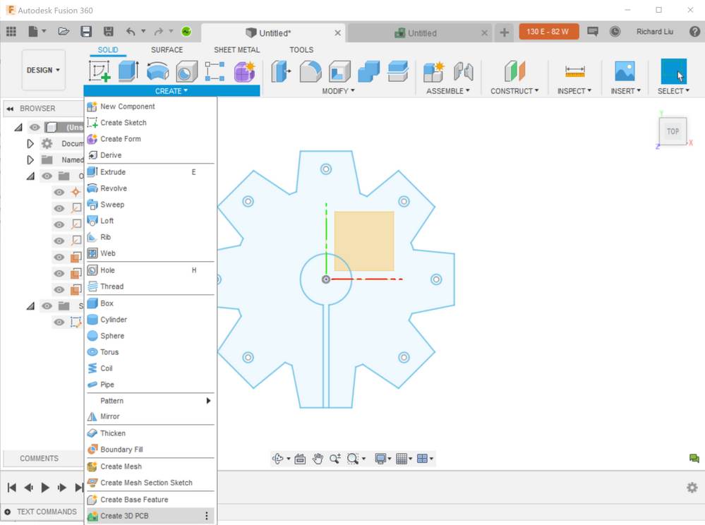
This process will create a new 3D PCB document and you can use the Push to 2D PCB or Link to 2D PCB command to associate it with a 2D PCB.
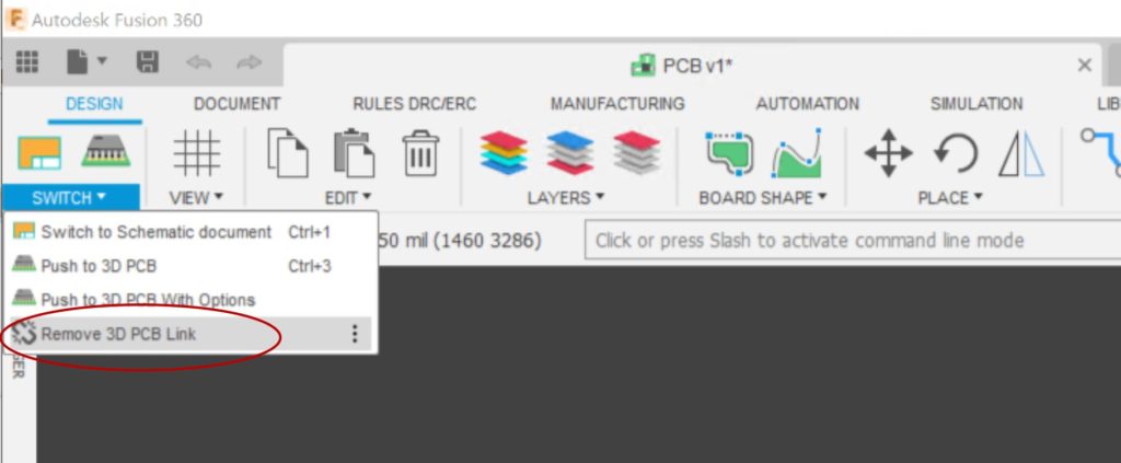
5. How can I break the link between 2D and 3D PCB?
2D and 3D PCBs are linked so that the documents know whether the two are in sync or not. If you want to break the link, either because you want to create a new 3D PCB document, or something is wrong with the link, you can go to the 2D PCB environment and click Remove 3D PCB Link.
6. How to edit the board outline in 3D PCB Workspace?
The 3D PCB is created as a parametric model. You can edit the sketch or the board feature to change the outline.
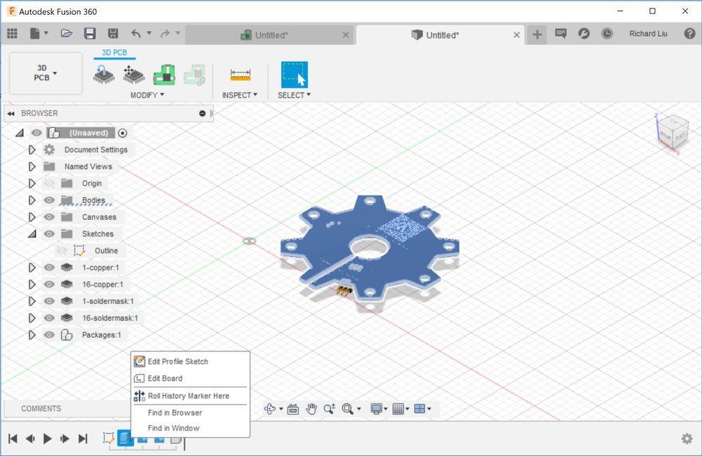
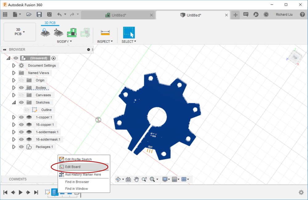
Sometimes you may want to add a hole on your board. If you put a circle on the sketch, you may find that it doesn’t cut a hole on the 3D PCB. This is because Fusion 360 doesn’t understand your intention if there are many profiles. You can explicitly specify the board outline after clicking the Edit Board command:
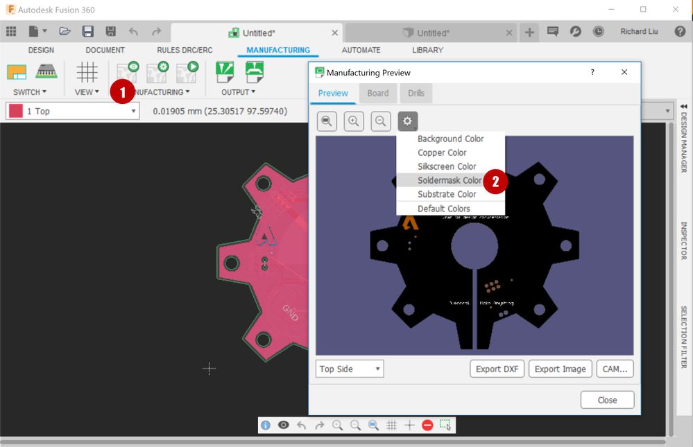
7. How can I change my board’s color?
You can change the color of the solder mask, copper, etc. in the Manufacturing Preview dialog:
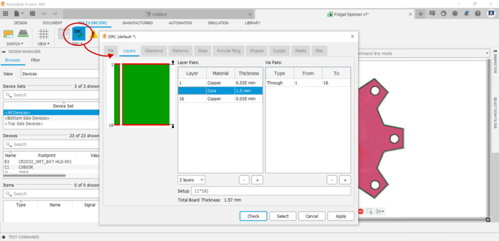
8. How to set my board’s thickness?
Board thickness is defined by the DRC of the 2D PCB. Note that currently Fusion 360 3D PCB only supports two-layer boards. If you create a board of 4-layer or more, the middle layers will be ignored in 3D PCB as of writing.
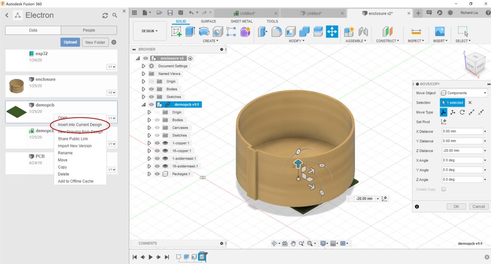
9. How do I insert my 3D PCB into a mechanical design (like an enclosure)?
Open your mechanical design first, then find your 3D PCB from the data panel and right-click, select Insert Into Current Design.
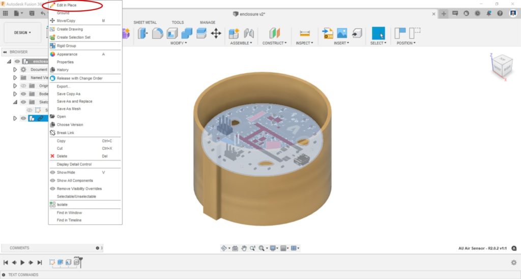
10. How do I edit my 3D PCB inside a mechanical environment?
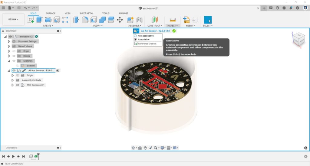
Once you insert a 3D PCB into an enclosure, you might want to adjust the position of the part by referencing the shape of the enclosure. To do this, right-click on the 3D PCB node in the browser and then select the Edit in Place command.
Edit in place is a very powerful feature. You can even create associative references to the enclosure for the 3D PCB. For example, when you move a part, you can reference a face of the parent document.
Please refer to the Fusion 360 documents for more information about Edit in Place.
11. Can I make my enclosure update when I change my board outline?
So far, we don’t support two-way updating when working with 3D PCB. This means you will need to decide whether MCAD or ECAD is driving. If you want the mechanical part to always update when you change the board outline, we recommend designing the board outline first and then creating the mechanical part based on the projected outline sketch.
12. Can I make my board outline update when I change my enclosure?
In some workflows, the outline design is driven by MCAD. In this case, it’s ideal if when you change your design on the MCAD side, your outline on the ECAD side can easily update. If you are experienced with Fusion 360 mechanical design, you can use the Derive command to achieve this. However, the Derive command involves many steps. Now, we have a special command called Derive PCB from Sketch for this requirement.
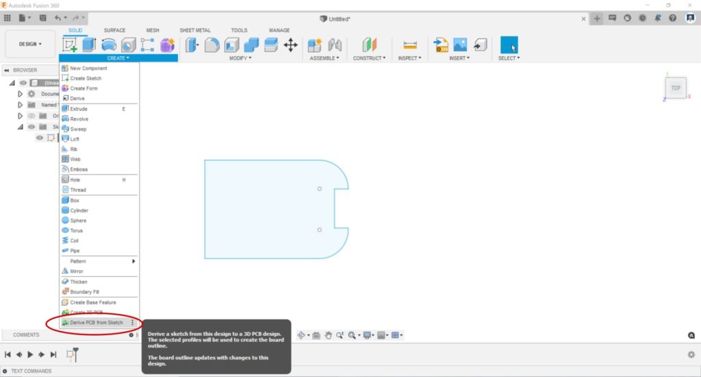
The Derive PCB from Sketch command works like Create 3D PCB, but it keeps associativity with the source sketch. So, if you change your sketch, your 3D PCB can track the changes.
If you design the enclosure first and then derive a PCB from a sketch in the enclosure design, you cannot insert your 3D PCB into the enclosure anymore. This is because this workflow generates a circular dependency. To avoid this issue, you can put the outline sketch into a third document and then insert both this document and the 3D PCB as external references into the enclosure design.
If you have additional questions about electronics workflows, the Fusion 360 Electronics Forum is the best place to post them and find support from our team of electronics experts. Not using Fusion 360 Electronics yet? Here are five reasons to start.