This post is also available in: Italiano (Italian) Deutsch (German)
PCB design revisions used to be costly and time-consuming. Not anymore! Here’s why PCB designers need 3D modeling software.

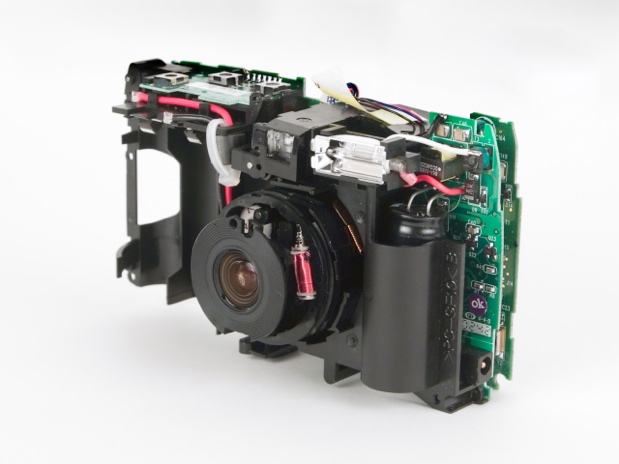
In the early days of PCB design, designers focused on placement and routing. Mechanical engineers focused on ensuring the PCBA (printed circuit board assembly) fit within the enclosure. After fabricating the PCBA, the assembled prototype would be sent to the mechanical engineering team for fit verification. That’s how it worked in larger companies, at least. In smaller companies, the PCB designer might also take on the role of a mechanical engineer.
Either way, mechanical problems were usually undetected until the PCBA prototype was complete. If holes didn’t line up, capacitors were too tall, or cut-outs were forgotten — well, all these problems meant a re-spin of the PCB or mechanical design. Revisions to designs were costly and time-consuming, as was the communication between the PCB designer and mechanical engineer.
It doesn’t have to be that way. In this article, we explore five reasons why PCB designers need 3D modeling software.
1. Update your PCB in real time

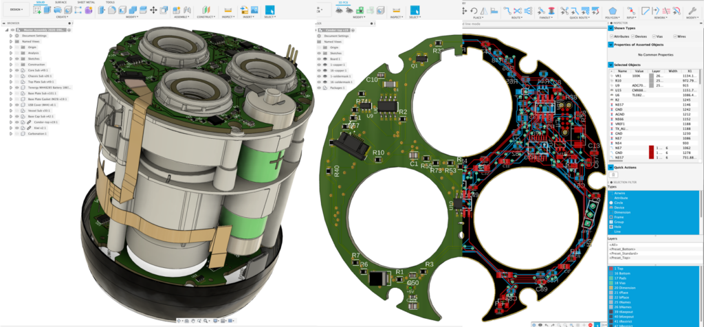
3D modeling PCBs allows you to see what your design looks like immediately, and you can make changes to it in real time. You can easily see if parts are blocking other parts, and you can even integrate your PCB into a 3D model of your enclosure to check for collisions.
Autodesk Fusion 360 creates an actual 3D model of your PCB, not a rendering. Having an existing model means the mechanical design is made up of 3D objects, not a “picture” of what those 3D objects would look like.
Say one of your suppliers has a replacement part — simply swap out your existing part with the new one and immediately see if there will be any problems with the fit.
2. Move components and traces
With Autodesk Fusion 360, the PCB designer or mechanical engineer can move parts around to accommodate changes, and both parties can see the results immediately. What’s more, Fusion 360 can move and re-route traces! Check out the video above to see the process in action.
3. Run simulations
Another advantage of 3D models is that they can have properties assigned to them. You can run simulations on these properties to provide a thermal profile of your PCB, highlighting hotspots early in the design process. Learn more about running simulations in the above video.
5. Eliminate file confusion
Using one piece of software for PCB design (ECAD) and another for mechanical design (MCAD) introduces issues. Converting files from one CAD environment can result in translation errors, and revisions do not display between software from different vendors.
Autodesk Fusion 360 is a unified MCAD and ECAD environment, so there are no export or imports of intermediary files. You only have to deal with one software, and everyone works from the same shared file.
4. Collaborate seamlessly
Since PCB designers and mechanical engineers share one file and can make changes to it in real time, collaboration becomes more seamless.
If the mechanical engineering team needs to modify the enclosure and associated PCB outline, the PCB designer sees the changes reflected immediately. Similarly, the PCB designer can change components on the PCB, and the mechanical team can see those changes in their 3D model.
Every revision saves with notes, so those involved in the design can select the best revisions or view the implications of revisions. Yes, you can go backward or forwards through revisions selecting the ones that work best!
What are you waiting for? Try Autodesk Fusion 360 electronics for your next PCB design and start unifying your ECAD and MCAD data today:
