& Construction

Integrated BIM tools, including Revit, AutoCAD, and Civil 3D
& Manufacturing

Professional CAD/CAM tools built on Inventor and AutoCAD
3 min read
Many things in the world of CAM can be tricky, but one aspect programmers should never neglect, if they want their tools to last, is how they plan to machine internal corners. In this post I will explain why analysing the internal radii on your model is very important when programming your toolpaths.
Let’s take, as an example, the part you can see in the image below. As we can see, there is quite a lot of concave radii on this Setup.
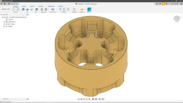
The risks here, if I chose the wrong tool, would be to gouge the part, leave some unmachined material behind, or even break the tool, all undesirable outcomes in the world of manufacturing. When a tool enters a corner, its engagement angle with the material will inevitably grow, subsequently increasing the forces acting on the cutter and resulting in a potential tool break or bad surface finish due to tool deflection.
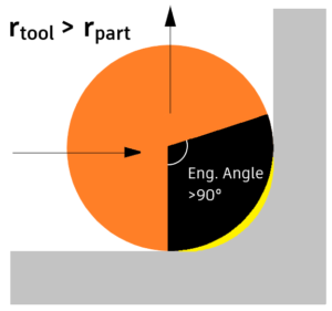
Let’s now look at three possible scenarios. First, for example, using an 8 mm ball nose tool to machine a surface with a 3 mm radius would inevitably end up leaving material on the part, which in turn would result in the need for additional toolpaths to complete the programme, as you can see in the image below.
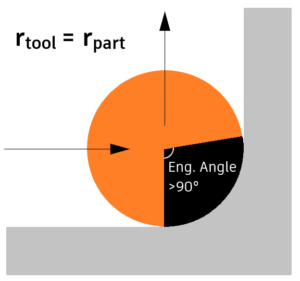
In our second scenario, using a tool radius that matches exactly the part radius wouldn’t leave any undesired material, but would cause a sharp increase in the engagement angle, which could damage our tool, as I mentioned earlier.
The third option we have is to use a smaller tool. Keeping in mind that we will still experience an increase in the engagement angle, a slight reduction in the feed rate would cope with the problems caused by the increasing cutting forces, leaving a better surface finish and decreasing the chances of a tool break.
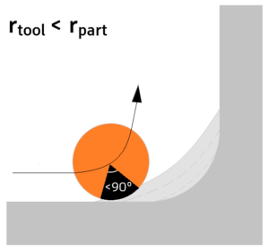
Overall, the last scenario I depicted is the most desirable and effective one. As a rule of thumb, I would recommend a tool radius that’s 80% of the minimum concave radius you have to machine.
Let’s now see together how we can be sure to choose the correct tools to machine the internal corners on the part we are about to program. What I always do first is run a quick Minimum Radius Analysis within the Manufacture workspace.
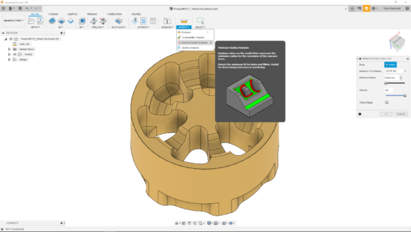
For the part you see in the image, I found the sweet spot at 5 mm, as you can see in the image below. Therefore, I know that I can use a tool with a maximum diameter of 8 mm, as I’d be exactly on the 80% mark I mentioned above, if I don’t want any issues.
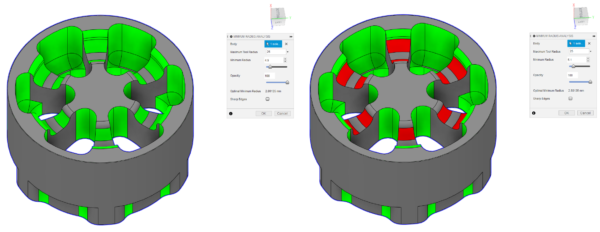
Another option you have (unless the design specifications don’t allow you to) is to modify the radii to accommodate for the tools you have available. Let’s say I want to modify the 5 mm radii highlighted in red in the image above, as they were the smallest I found. All I need to do is go to the Design worskpace, select the surfaces, then open the Press/Pull tool and select the desired value for the radii.
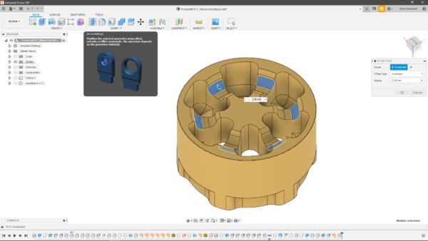
Now that my minimum radius is 6 mm, based on what I said before, I could use a tool with a maximum diameter of 10 mm, if I wanted to, as my tool radius would be around 83% of the radii to machine.
I hope this post helped highlighting the most important aspects to consider when machining internal corners on your components. If you haven’t tried out Fusion 360 yet, you can download a free trial at this link.
By clicking subscribe, I agree to receive the Fusion newsletter and acknowledge the Autodesk Privacy Statement.
Success!
May we collect and use your data?
Learn more about the Third Party Services we use and our Privacy Statement.May we collect and use your data to tailor your experience?
Explore the benefits of a customized experience by managing your privacy settings for this site or visit our Privacy Statement to learn more about your options.