& Construction

Integrated BIM tools, including Revit, AutoCAD, and Civil 3D
& Manufacturing

Professional CAD/CAM tools built on Inventor and AutoCAD
4 min read
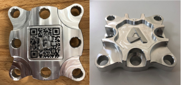
After telling you everything about the design and manufacturing process behind the Wheel Hub component, today I’m going to explain in detail how to machine a Spider Plate like the one pictured in the image below, utilizing the integrated CAD and CAM capabilities offered by Autodesk Fusion 360. If you want to see some machining footage of us actually machining the part, visit this link.

As I mentioned in the post about the Wheel Hub, the choice of which side to machine first, is one of the most crucial decisions a CAM programmer has to make. In this case, however, I was lucky, as the part is pretty much symmetrical about the XY plane, meaning I could have chosen either side to be machined first. The design of the part included six clearance holes and two dowel holes. This was a massive help for making sure the part was correctly positioned and held during the two setups needed to fully machine it. In the end, I chose to machine the bottom of the part first, the one on the left-hand side of the image below, where you can also see the QR code I laser engraved.
For this component I decided to hold the original billet in a Lang vice, an excellent tool that guarantees reliable and vibration-free holding, whilst only needing 3 mm of material to clamp on. Lang vices also allow for re-alignment of a component (after removing it and placing it back) within a 5-micron tolerance. This makes processes highly repeatable, compared to other work holding mechanisms. As I planned on cleaning up 10 billets before starting with the actual programs, this made my life much easier when making sure I aligned the blocks correctly before running my toolpaths.

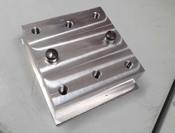
Another essential aspect when manufacturing any component is the choice of a fixture. In this case, as the component is flat at both ends, it was easy to design a simple plate with 8 holes, six for the clearance holes and two for the dowels. Making sure you aligned correctly the fixture holes with those on the part is crucial even when it comes to “simple” 2.5D components like the Spider Plate. Double-check before starting your program!
During the first Setup, for the external roughing of the component, I used 2D Adaptive Clearing with a 16mm End Mill. The algorithm behind this toolpath makes sure I can use the full flute of the cutter for clearing material out. This meant I could rough the outside with a single pass (make sure you have enough cutting length on your tool before doing this!). This strategy allows the cutter to be under constant load, by keeping the engagement angle between the tool and the material constant. This results in much safer and faster roughing, compared to more traditional strategies.
I machined the part out of Aluminium 6082, on a DMG Mori DMU 60eVo linear. Even if the choices of machine and material to use have been finalized, it is still very important to run a thorough geometry analysis on the part, as the radii present will dictate the maximum size tool you are allowed to use for your toolpaths. In this case, in both setups, I decided to use 2D Pocket toolpaths with a 12mm End Mill for all open pockets, as I found a minimum radius of 7mm, meaning I could machine them with my 12mm tool without gouging on the sides. If you want more details on how to choose the right tool for your internal radii, please see this post on how to machine internal corners.
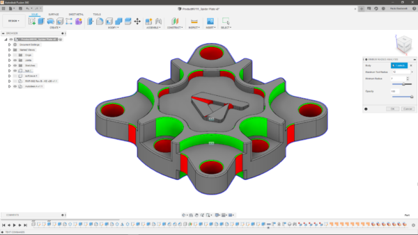
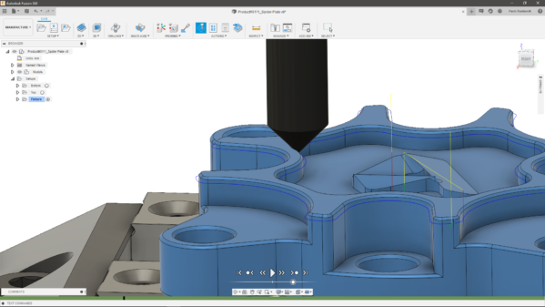
One tricky aspect of this part was that I found it impossible to machine the chamfers at the bottom of the open pockets with a chamfering tool, as it would have gouged on the sides. Therefore, I decided to machine those chamfers using a 2mm Ball and a Scallop toolpath, as you can see in the image below.
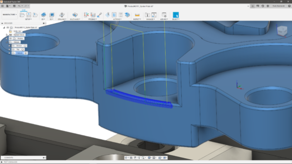
I chose the same combination of 2mm Ball tool and Scallop toolpath for the Autodesk logo in the centre of the part, combined with an Adaptive Clearing strategy for the freeform pocket around the logo.
Finally, for the chamfers on the holes, as there was no risk of gouging, I used a 2D Contour toolpath with a Chamfering tool. I used the same combination of tool and toolpath for all other chamfers on the part. I found 2D Contour works really well for chamfers, as it allows for quick programming and cutting, without having to spend time creating sketches to drive my tool.
The overall cutting time for the component was around 45 minutes, but the complete process took a bit longer, considering I had to switch the bolt positions halfway through each setup, to machine 4 pocket (and relative holes) at a time.
I really hope you found this post useful and have now learned how to machine a Spider Plate.
Fusion 360 integrated CAD/CAM tools made the whole design and manufacturing workflow quick and seamless, as it was easy for me to switch workspaces whenever I needed to. If you want to give this a go, but haven’t tried out the software just yet, you can download a free trial at this link.
By clicking subscribe, I agree to receive the Fusion newsletter and acknowledge the Autodesk Privacy Statement.
Success!
May we collect and use your data?
Learn more about the Third Party Services we use and our Privacy Statement.May we collect and use your data to tailor your experience?
Explore the benefits of a customized experience by managing your privacy settings for this site or visit our Privacy Statement to learn more about your options.