Having trouble understanding electrical impedance? Don’t worry; you’re not alone. Let’s get practical.
Are you trying to understand electrical impedance? Chances are, if you’ve dived into this topic in the past, all you got was some jargon like phasors, phase relationships, and even imaginary resistance. What in the world is all of that?!
Whether you’re a professional electronics engineer looking for a refresher on the formulas you learned in college or if you’re just tinkering around with electronics in your spare time, understanding impedance shouldn’t be a drag. If you’re planning to work with AC-powered electronic devices, then you’ll want to know what impedance is and what it’s doing to your circuit.
Let’s find out!
Not quite apples to apples
The best way to understand electrical impedance is to compare it to something you’re already familiar with — resistance. And this is where we’re going to offer a one-sentence summary of impedance in a nutshell:
Electrical impedance is just a form of resistance that depends on frequency.
That’s it. You could walk away right now and add one more word to your electrical engineering vocabulary. When you break impedance down, it provides a form of resistance to a current based on the operating frequency of the circuit. But of course, there’s more.
Resistors have a pretty easy job in a DC-powered circuit; they resist the flow of current flowing through some kind of metal like copper. If you throw a 220K Ohm resistor into a DC circuit, you’ll get a definite reduction in current between one side of the resistor and the other. Resistors, like other nonreactive components, could care less about things like the frequency of the power source. They’re just going to keep doing what they do, resisting the same amount of current all the time.
But what happens if you start to work with AC-powered electronics? With AC, it’s not just a simple matter of 5V powering your circuit. Instead, you have new variables to consider, like the particular frequency of your AC current. Here in the United States, AC moves back and forth at 60 cycles per second (60Hz). Over the pond, in Europe, it’s switching at 50Hz.

The point of all this is, in AC-powered electronics, you not only need nonreactive components like resistors to resist current. You also need components that can react to the changes in current and frequency, like capacitors and inductors; otherwise, your circuit won’t work as intended. Put all of this together, and you can almost think of impedance as the bigger brother of resistance. Impedance includes both resistance and reactance. Or expressed as a relationship:
Impedance = Resistance + Reactance
What is reactance?
Reactance comes in two different flavors depending on which reactive component you’re using:
Inductive reactance
You’ll see this in the form of electromagnets that change the magnetic field in a circuit, also called an inductor. Inductors will have a low impedance at low frequencies and a high impedance at high frequencies.

Capacitive reactance
You’ll see this in the form of a charging electrical field between two conductive surfaces, also called a conductor. Conductors have high impedance at lower frequencies and low impedance at high frequencies.

Put resistors, inductors, and capacitors into an AC circuit, and you not only have the opportunity to resist electricity, but you also have the ability to store and release energy. While a resistor will hold a steady resistance regardless of changing conditions, inductors and capacitors will change their resistance based on the frequency of the signal that they’re presented with. And when capacitors and inductors are both resisting and storing/releasing energy, then you have a measure of impedance.
How do you measure impedance?
Let’s take a simple circuit to tie all of this together. Take a look at the first one below; it’s a DC-powered circuit with current flowing through a resistor. Pretty simple, right? The higher the resistance in this circuit, the lower the current will be.
But what happens if you upgrade this circuit with an AC power source, an inductor, and a capacitor? Now you have two additional components offering their own form of resistance to the electrical current. Just like the resistor, they’re both impeding the flow of current while also reacting to it. When you combine the resistance of your resistor and the resistance and reactance of your capacitor and inductor together, then you get yourself a total impedance.
But hold on, calculating impedance isn’t as simple as adding your resistance and reactance together, and this is where most tutorials start off with a bunch of mathematical formulas. So let’s take this part slowly.
Calculating your capacitor impedance
To calculate the impedance of our capacitor, you can use the formula below. Here, XC is the total impedance that you’ll get, which is measured in Ohms (Ω). f is the frequency of the signal through your capacitor, and C is the capacitance.
XC=1/(2πfC).
Calculating your inductor impedance
To calculate the impedance of our inductor, you can use the formula below. Here, XL is the total impedance that you’ll get, which is again measured in Ohms (Ω). f is the frequency of the signal through your inductor, and L is the inductance.
XL= 2πfL
These formulas are all fine and great if you just want impedance measurements for individual components, but what if you want to know the total impedance for your entire circuit? That’s where things get more complicated.
Before we head into our last formula, we want to offer you an impedance calculator that can make your life easier: Impedance Calculators by Keisan.
Calculating your total impedance
You’ll need to enlist the help of Pythagoras theorem to get the job done. As we’ve explained above, in AC circuits, you’ll work with both resistance and reactance, which comes together to give you a total impedance. But it’s not simply a matter of adding your resistance and reactance together. We could explain why, but that would dive into the intricacies of vectors and phasors, and that’s a whole blog in itself.
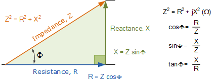
When you break down the process of calculating impedance for an entire circuit, then you’ll wind up with what’s called an impedance triangle, check it out below:

The most important part of this triangle is the hypotenuse, which gives you your total impedance based on the square root of both your reactance and resistance. If you put this into a formula, you can find your total impedance with the formula below. Here, Z is your total impedance, R is your total resistance, and X is your total reactance.

Impedance made practical
See, understanding electrical impedance isn’t so hard after all. There are a ton of free calculators out there to help you get the job done. What you really need to know is that impedance works just like resistance by impeding the flow of current in an AC-powered circuit.
It’s the ability of components like capacitors and inductors to react to an ever-changing AC current that makes them unique. Because of impedance, you can have something like a fuse box in your house that will react to an unexpected electrical surge, preventing your house’s electrical system from getting fried. And you can also thank impedance for being able to carry a portable laptop around, knowing that your batteries are fully charged without exploding first.
When it comes to working with AC-powered devices, whether that’s your laptop or the fuse box in your house, you have impedance to thank. And remember, electrical impedance is just the bigger brother of resistance, combining resistance and reactance in one simple formula.
Ready to get started with your first AC-powered electronics design? Try Autodesk Fusion 360 for free today!