& Construction

Integrated BIM tools, including Revit, AutoCAD, and Civil 3D
& Manufacturing

Professional CAD/CAM tools built on Inventor and AutoCAD
12 min read
Software is a beautiful thing. Always changing, always evolving, always striving to keep up with the new demands of our engineering age. The best software out there fits our workflows like a well-worn glove, shaping around our needs like it’s a natural extension of our abilities. But software that just feels clunky, dated, and disconnected? That’s software that becomes obsolete.
If there’s one thing for certain about today’s design, it’s that things are changing dramatically, but in the world of ECAD software, we’re struggling to keep up with the change. Gone are the days of separately designing PCBs, and separately making enclosures, everything is connected. But here we are, working with tools that are still competing, and still struggling to communicate. Things need to change. Autodesk EAGLE 8.3 is taking EDA where it has never been before, ushering in a whole new dimension of PCB design.
PCB design problems are universal. Does anyone out there not struggle to collaborate with their mechanical engineer? Or does anyone not do the back-and-forth dance with their manufacturer with emails and phone calls? And does anyone not spend more time than they would like trying to properly document their design, only to find out a respin is lurking just around the corner?
These are problems that plague every electronics designer out there. I don’t care where you’re from, or where you work. Chances are if you’re designing electronics, then you’re dealing with at least one of these problems. And all of these are problems we want to fix, or at least lay the foundation for future fixes, in Autodesk EAGLE 8.3. At the root of these problems is an underlying issue with data, and we all play the same game:
The focus of this release then is all about addressing the root cause of these engineering problems that have been bogging down our minds and methods for decades. Because if we’re ever going to work together, if we’re ever going to get into the mindset of designing products, not just PCBs, then it all has to start with our data. So without further ado, let’s look at how we’re using this intent in our biggest release so far, Autodesk EAGLE 8.3.
We all know the drill in EAGLE, you start your board layout with a generic lined box on the Dimension layer, and that’s about the best you’ll get as far as board shapes go. But does this “dimension” actually mean anything outside of a set of lines? Nope. We’ve improved this with the new Board Shape object.
This Board Shape Object will allow you to create a fully-fledged physical shape for your PCB that isn’t just a set of connected lines; it actually includes some built-in data.
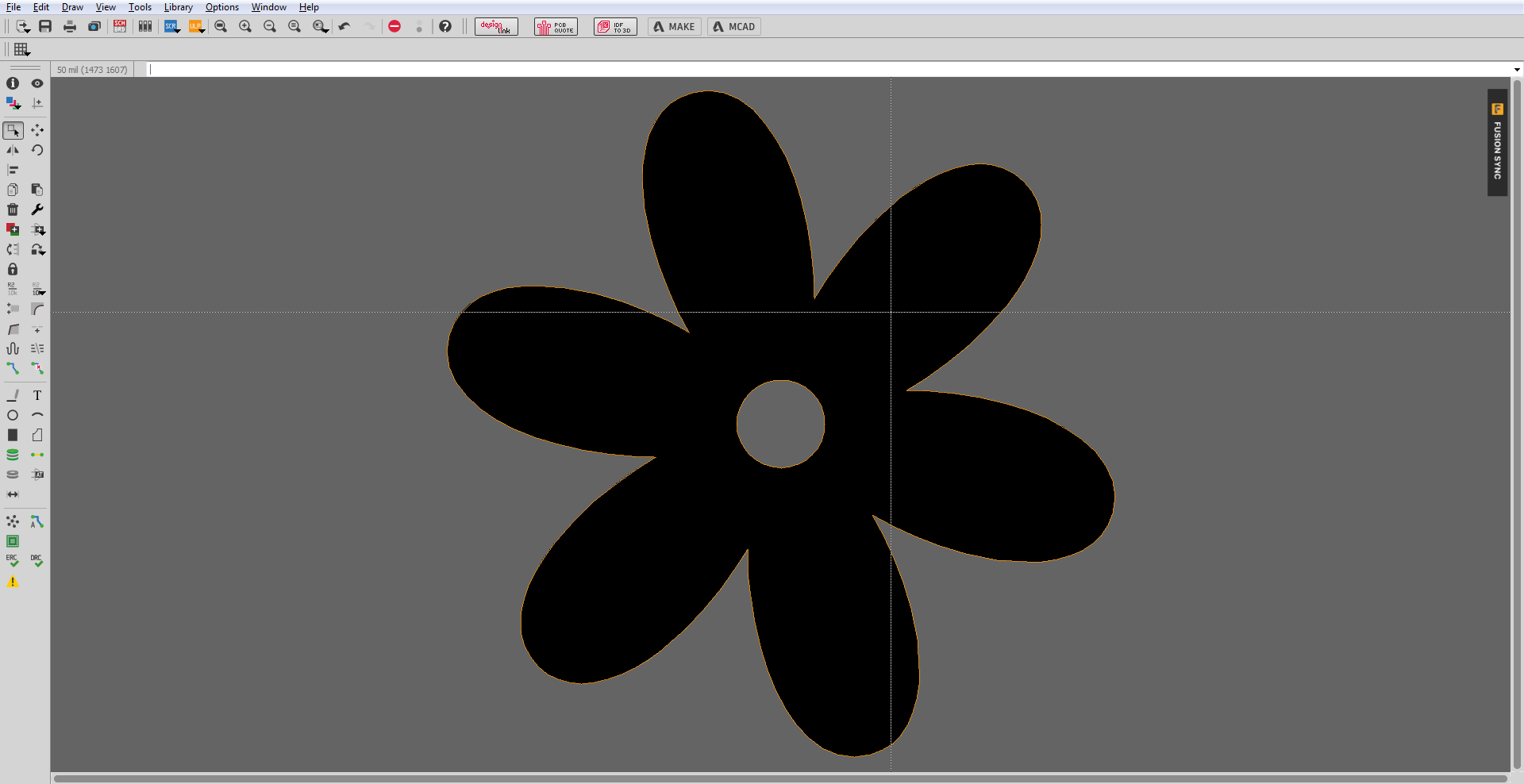
For example, you can now use the Board Shape to create a shape that includes dimension and mill information, all while being a physical object that can interact with your DRC. Are your components placed too close to the edge of your board? DRC will know where that edge is now, based on the new Board Shape object.
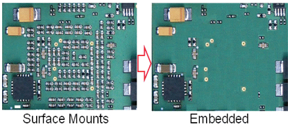
Adding an actual board shape object is one major step towards laying the groundwork for future manufacturing and ECAD/MCAD features. In the future, we can start adding new attributes and features, including things like 3D, custom shapes, customizable cutouts, embedded passive designs, and a whole lot more.
This new board shape tool is even going to help with our plans for board analysis and simulation. How can you run those kinds of simulations when the original board shape in EAGLE had no intelligence or data behind it? You couldn’t.
For manufacturing, imagine being able to define all of the specifications for your board materials and layer stackup right in EAGLE. Overall, this feature will make your life a whole lot easier when all of that rich data gets automatically packed into your manufacturing data, without you having to call anything out or create special notes.
You likely have a ton of old designs in EAGLE, and we haven’t forgotten about those with this new feature. Here’s what to expect – when you open an existing design in Autodesk EAGLE 8.3, the software will look for any closed bounding boxes on the Dimension layer. If there is one, it will be replaced with the new Board Shape object without you having to do a thing. And if EAGLE detects any closed bounding boxes within your newly established board shape, then it will define those as cutouts. Boom!
We all know that routing is an exercise in focus, and having to do anything out of the ordinary can totally pull you out of your zone. So those days of having to pop open your layer panel and sort through 52 different layers just to get yourself in a visible-layer set up have come to an end. After all, who has time for that frustration!?
The new Single Layer Mode makes it simple to filter out all existing layers from your view except the one that you’re working on, all with a click of a button ![]() (or type SET SINGLE_LAYER_MODE On in your command prompt). When this option is applied, all of your non-active layers will become grayed out and muted. We’ve also made it easy to see exactly which layer is selected when sifting through complex layer stackups.
(or type SET SINGLE_LAYER_MODE On in your command prompt). When this option is applied, all of your non-active layers will become grayed out and muted. We’ve also made it easy to see exactly which layer is selected when sifting through complex layer stackups.
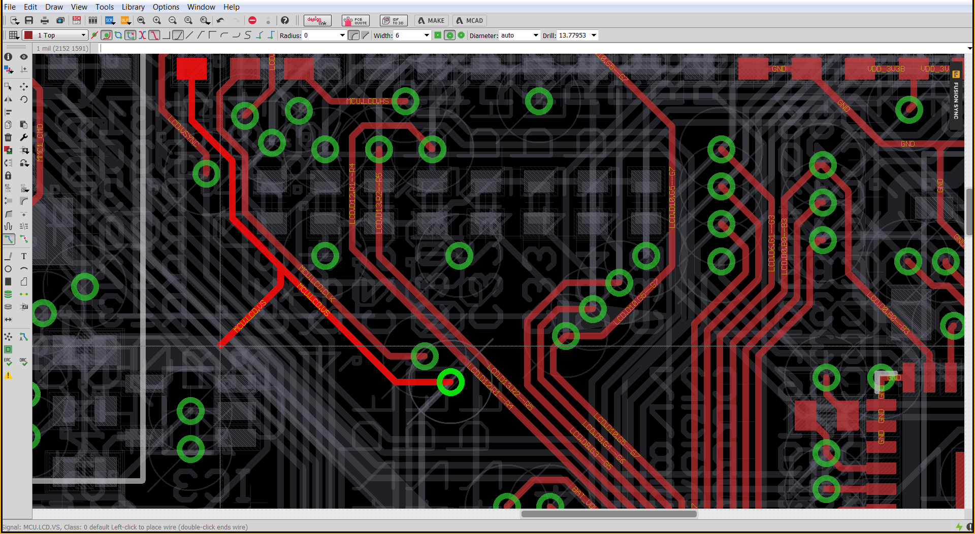
You might be working on two layer boards now, but what happens when you get to six? Trying to route when you have six visible layers all at once can be a nightmare and opening that layers panel can get frustrating. Single Layer Mode stands alone on its own as a tool of efficiency and focus. We wanted to make it easy to remove all of the visual clutter from your engineering life so you can focus on what matters. All without having to open another menu and tick a bunch of boxes just to get the result you expected.
Here it is, we’ve got a feature that gets to the core of a data-focused problem and also causes a lot of frustration for every engineer – ECAD/MCAD collaboration. We’ve all been there, sending our board files through email and tracking changes through spreadsheets. At its worst, this problem manifests itself as an enclosure that doesn’t fit at the last minute, and a complete layout rework. Simply put, all of these problems are horrible, which is why we’re excited to introduce Fusion 360 interoperability in Autodesk EAGLE finally.
This feature has required a ton of back-end work to get Fusion 360 and Autodesk EAGLE on the same page. As you can imagine, this was no easy undertaking and required several individual components to be put into place to make the whole operation work. Here’s how it breaks down:
First, we addressed one of the biggest problems with ECAD/MCAD collaboration, having available 3D models for each component on your board. We’ve solved this by creating an Online Library Editor for our recently introduced Online Managed Libraries.
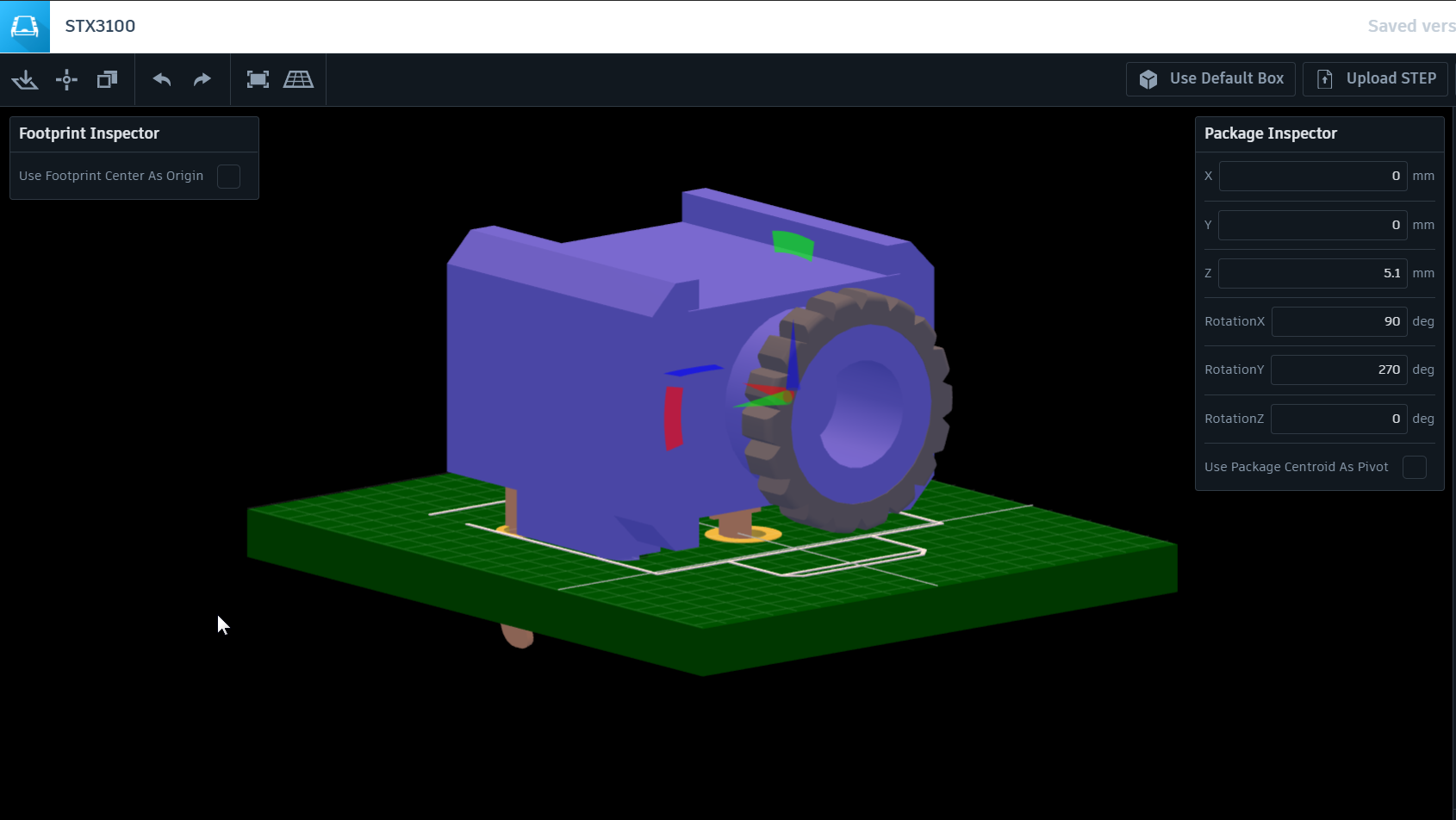
This editor will allow you, or third party vendors like Sparkfun and Adafruit to attach 3D models to our growing online parts catalog. Within this editor, you’ll be able to easily add or edit the footprint for the package and add/create 3D models as needed. Once you save changes to either a new or existing package, a new version of the package gets created and ready for use from your Add dialog in Autodesk EAGLE.
Once you upload your libraries you can add your 3D package within this editor.
To build on top of the Online Library Editor, we’ve also added a helpful icon next to each Online Library in EAGLE that has an included 3D model. If you decide to add one of these parts to your design, then the 3D model will automatically be embedded and available when you share your design with Fusion 360.
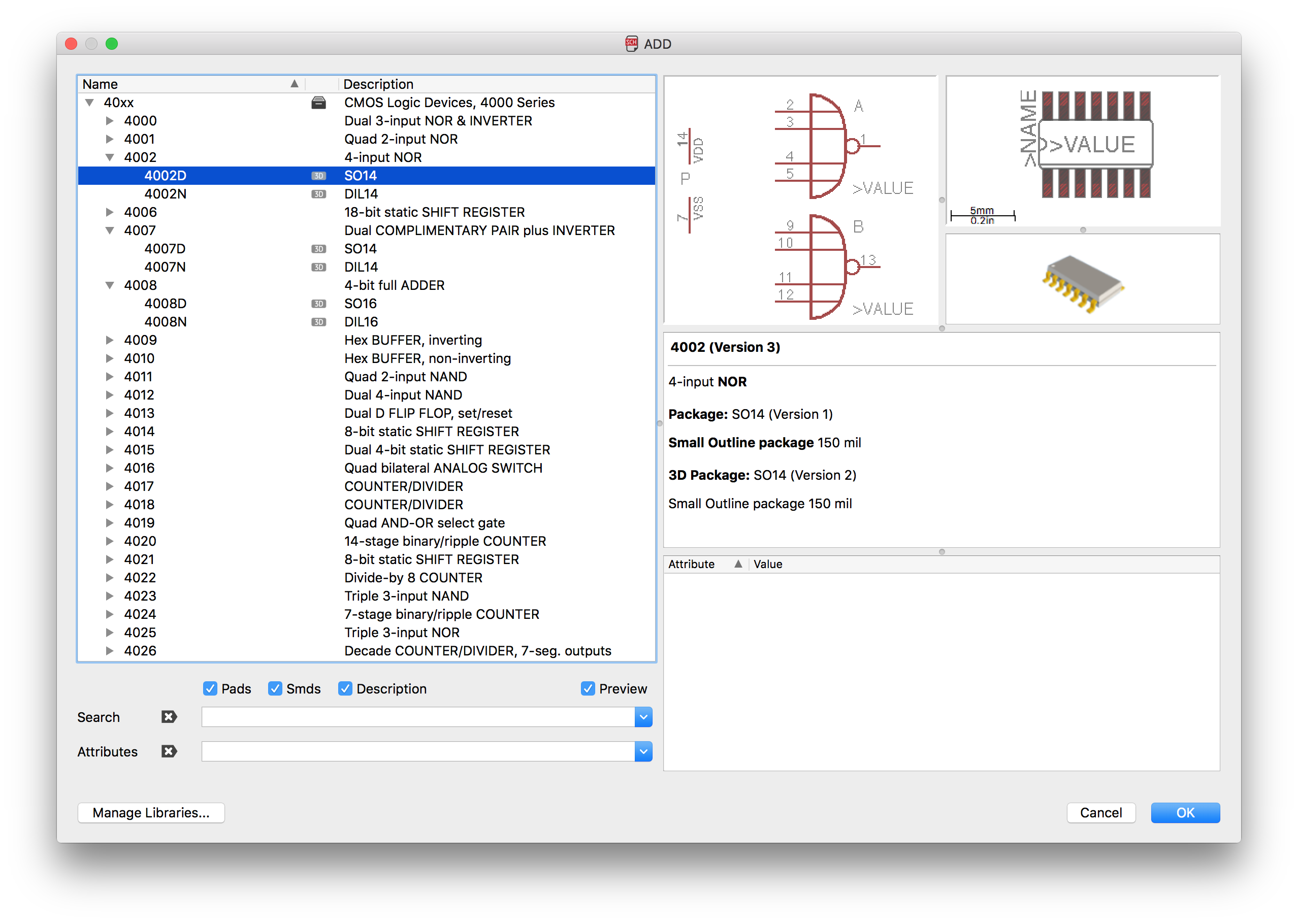
You can also see a preview of the 3D model directly in the Add dialog.
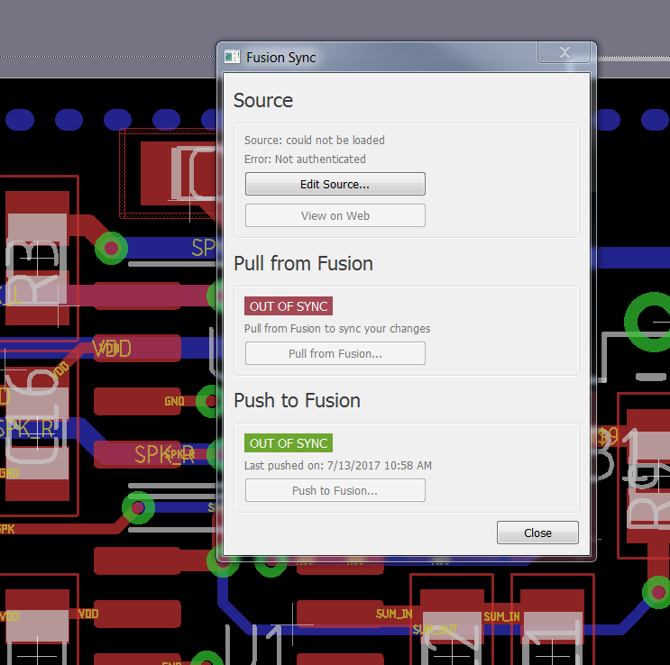
Next, we’ve established core functionality that will allow you to easily link your EAGLE .brd file to a Fusion 360 PCB file. Within Autodesk EAGLE you’ll see a new Fusion Sync dashboard that allows you to integrate your board file with its 3D representation in Fusion, and this is where all of the magic happens for true ECAD/MCAD collaboration.
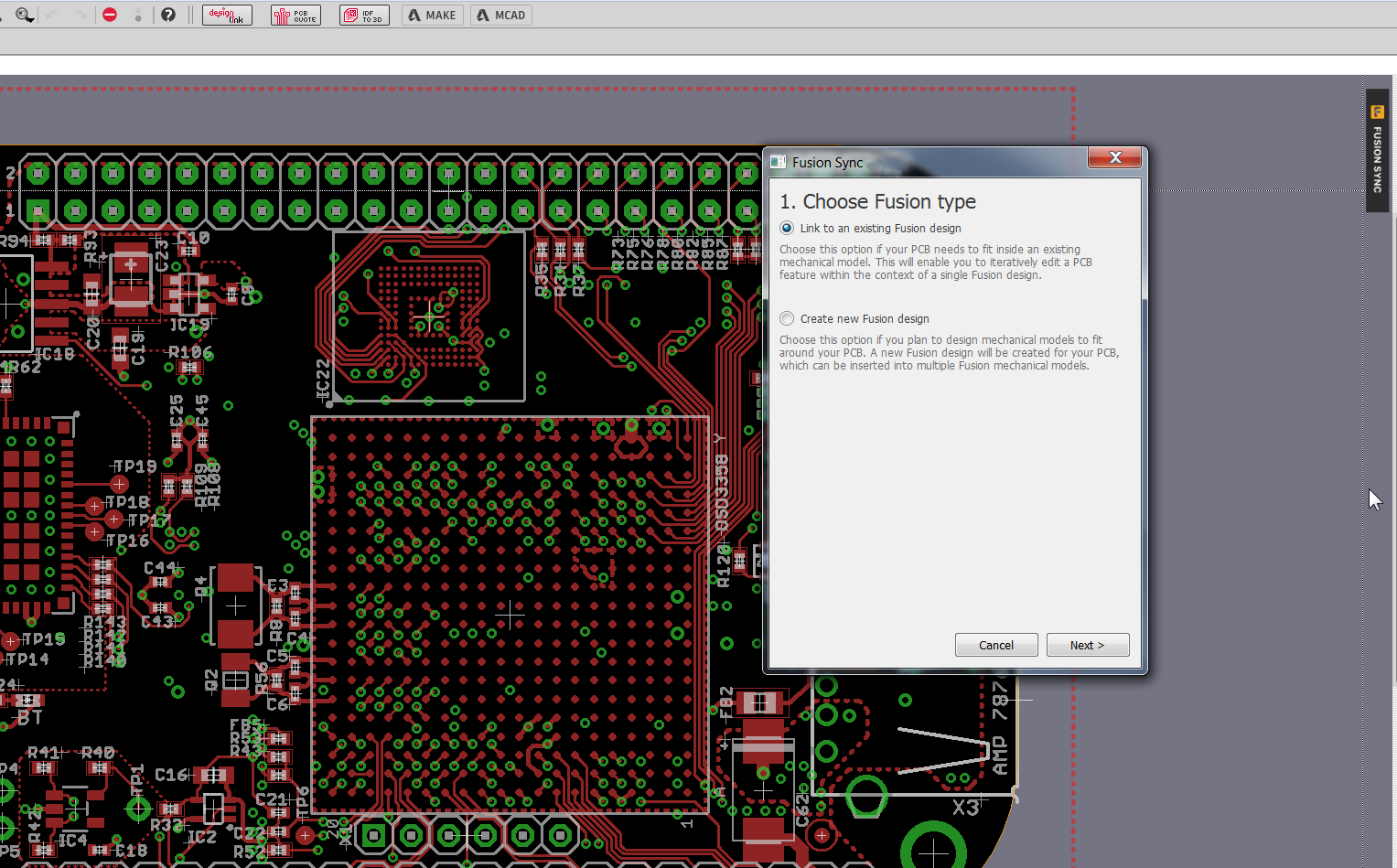
We know that every engineering workflow is unique, so we’ve built this system with flexibility in mind. Here’s how you might find yourself working with EAGLE and Fusion 360:
These two workflows come together to offer what we’ve always been wanting – true ECAD/MCAD synchronization and collaboration. Now changes can flow back and forth. If you update your board file, you can push those changes to Fusion, which will create a new version of a 3D PCB model for your mechanical designer. And if your mechanical designer needs to change the shape of your board or the placement of 3D component models, they can push those changes from Fusion to EAGLE, and you’ll be notified about the new update.
Finally, for our mechanical designers, we’ve added the ability to edit the 3D model of a PCB directly in Fusion 360. Your 3D PCB model will appear in your left-hand side project sidebar along with any other models you’re working on, and you can make the following changes:

There’s no way around it, electrical and mechanical engineers are coming together more than ever. Many of us aren’t just designing PCBs these days, or just enclosures. We’re designing products where electrical and mechanical blend together, and our engineering workflows need to do the same.
We respect the specialized needs of both electrical and mechanical engineers, that will never change. What we’re after here is to give engineers the tools they need that can communicate and collaborate with each other, and that starts by sharing a common foundation of data.
Ready to get started with true ECAD/MCAD collaboration? Try Fusion 360 for free today!
Check out the Fusion 360 What’s New Blog for all the new features! Oh and here is awesome video:
Ever wish you had an easy way to share your design not just with your mechanical designer, but with your entire team and extended teams? Now you do. Adding Fusion 360 Integration in EAGLE has some side benefits, like the new Fusion Team Collaboration tool.
The new Fusion Team Collaboration tool makes it easy to review your design in 3D right from your browser. Not only can anyone on your team view your design (after you send them a link), there’s also a ton of other powerful features like:
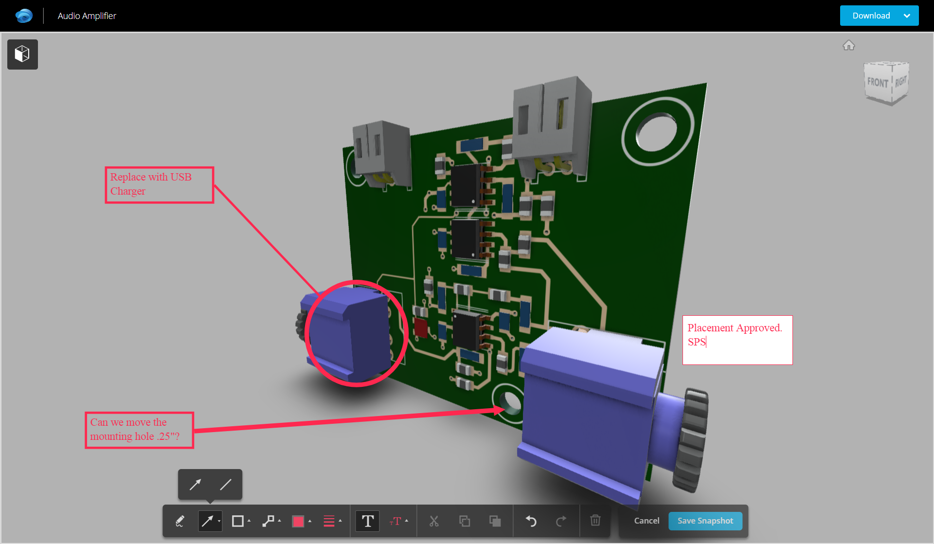
Basically, the new Fusion Team Collaboration is a complete collaboration, documentation, and design review tool that you can use anywhere. And by anywhere we mean any device with a browser, whether that’s your phone, tablet, or computer. Did we mention you get it for free, simply by integrating your ECAD designs with Fusion 360!?
Design review and collaboration is a critical part of the design process, but not everyone on your team has a copy of EAGLE. Now they don’t need it. Whether you’re having trouble communicating with your manufacturer or project manager, it’s as simple as sending someone a link to your design to provide the required perspective. This tool alone can skillfully tie your entire team into your process, whether that’s business, marketing, manufacturing, and of course, engineering.
Want to learn more about Fusion Team Collaboration? Check out Fusion Team!
A release this massive isn’t all about the new features. We’ve also been hard at work behind the scenes squashing bugs and improving the stability of your design tool across Windows, Mac, and Linux. Be sure to check out the Autodesk EAGLE 8.3 release notes to see all of the enhancements inside.
We want to do away with the emails, do away with the spreadsheets, and do away with all of the manual documentation. Because if you’ve spent hours, weeks, months, maybe even years crafting your design, wouldn’t you just expect your tool to know, understand, and be able to communicate all of that design intelligence? We think so, and this is the future that we’re working towards.
Ready to try all of the new features in Autodesk EAGLE 8.3? For our EAGLE Subscribers, open your software, and you’ll get notified to download this software for free!
For everyone else, head on over to our Free Download page to try out this release for free! And when you’re ready for the full experience, we’ve got an EAGLE Subscription waiting for you.
Be on the look out for some blogs showing you how to use these Fusion 360 interoperability features.
By clicking subscribe, I agree to receive the Fusion newsletter and acknowledge the Autodesk Privacy Statement.
Success!
May we collect and use your data?
Learn more about the Third Party Services we use and our Privacy Statement.May we collect and use your data to tailor your experience?
Explore the benefits of a customized experience by managing your privacy settings for this site or visit our Privacy Statement to learn more about your options.