& Construction

Integrated BIM tools, including Revit, AutoCAD, and Civil 3D
& Manufacturing

Professional CAD/CAM tools built on Inventor and AutoCAD
24 min read

V.2.0.9009
A bunch of you have reported to us that changing the quantity parameter on a previously committed Pattern on Path & Circular Pattern Feature didn’t work as intended. Apparently there was a bug preventing Fusion 360 to take the edits. Now it should work properly.
We also made some stability improvements under the hood so that Fusion 360 runs more stable for some of you experiencing hang-ups.
V.2.0.9006
Usability
Some of you running macOS 10.13.6 told us that the Navigation Bar at the bottom of the Fusion 360 window became invisible. Apparently it had to do with some of the improvements we made to our UI, yet 10.13 did not like it very much. We got this sorted out.
Sketching & Modeling
If you made a 3D sketch, turned off the 3D sketch option in the sketch palette and tried to dimension that 3D sketch, it may have caused Fusion 360 to become confused and close itself for no reason. We gave it a stern talk and now it won’t do that again.
Andy.c found a pesky Joint bug where it was causing Fusion 360 to crash when he tried to edit the joint. Our bad, we squashed this bug and now you can successfully edit joints without issues.
Electronics Design
Trevordjorgensen told us about an issue where adding a 3D package to the device in his custom library caused Fusion 360 to hang indefinitely. We looked under the hood and found some crossed wires. This issue has been fixed.
Drawings
We’ve noticed some unusual instability in the drawings environment where certain actions caused Fusion 360 to freeze. We dug into the code and sorted out a few kinks; everything should be running smoothly again.
Manufacture
There was an annoying issue in the Manufacture workspace that was causing Fusion 360 to become unstable when you were navigating between the tabs within certain toolpath strategy options. We got this sorted out and now you can go from tab to tab without a hitch.
Cody posted on our forum about some issues he’s been seeing with Fusion 360’s 3D Adaptive Clearing strategies. Apparently they wouldn’t generate correctly and was throwing a “Z Clearance is too low” error. We found this bug and swiftly got rid of it. It should generate fine now.
Goysimon told us about an error message he was getting unexpectedly: “All surfaces have been set to avoid”. Apologies for causing false alarms, we got this sorted now. We will further investigate why this was happening and implement a better experience.
API
Balunist told us that ValidateInputsEvent went missing after the last update, causing a bunch of add-ins with this event to no longer work properly. Sorry about that – this event has been restored.
V.2.0.8950
[toc]
[icon name=”star” class=”” unprefixed_class=””] New! T-Spline Cylindrify command for Form Struts
Design workspace > Solid Tab > Create Form > Modify Panel > Cylindrify
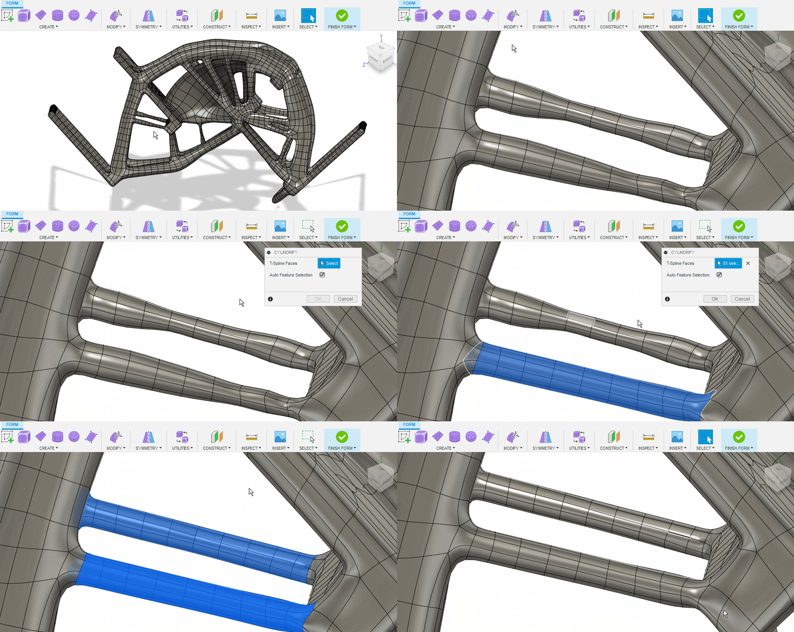
Now in the Modify drop-down menu in the Form contextual environment, you’ll find the new Cylindrify command. It forms uneven T-Spline geometry into a smooth cylindrical shape. This is especially useful to smooth uneven struts or holes from generative design results.
[icon name=”star” class=”” unprefixed_class=””] New! IGA Export
Right-click on a T-Spline body > Save T-Spine as IGA
You can now export T-Spline bodies to the IGA file format. IGA stands for isogeometric analysis. IGA technology allows FEA (finite element analysis) to be performed directly on certain types of models. This open format allows third party applications to perform analysis directly on data exported from Fusion 360.
[icon name=”thumbs-up” class=”” unprefixed_class=””] Improved! As-Built Joint Modes
Design workspace > Solid Tab > Assemble > As-built Joint
Now when you use the As-Built Joint command to join two components together, you’ll notice that we’ve also added modes like Joint Origin, Between Two Faces, as well as Two Edge Intersection, just like what you’ll find in the regular Joint command. Now you can easily choose which mode you want to use, making it more discoverable and easier to learn.
We have also improved the previewing experience of ‘Two Edge Intersection’ mode in Joint, Joint Origin and As Built Joint commands. We now show the JO preview when mouse hover over the second edge.
In addition to these As-Built Joint improvements and Two Edge Intersection previewing experience, we’ve also cleaned up a number of areas in the Joints experience. This includes the joint origin re-orient behaviors, preview compute issues in Joint, fixed buggy code that could lead to corrupted Joint origin, fixed the orientation inconsistencies seen between joints created through API and UI, consistent error messaging between parametric and direct modeling, better visual clue on the X, Y, Z offset values shown on its manipulator drag, better selection experience to know the participating faces/edges in Between Two faces and Two Edge Intersection ,as well as contextual disclosure of options in the command dialog, instead of showing everything at once.
[icon name=”thumbs-up” class=”” unprefixed_class=””] Improved! Mirror Command now has Join and Stitch
Design workspace > Solid Tab > Create Panel > Mirror
Now when you use the Mirror command, Join for Solid bodies and Stitch for Surface bodies are now available as options to use in the Operation drop-down menu. This should help reduce extra steps in your modeling workflow.
[icon name=”thumbs-up” class=”” unprefixed_class=””] Improved! Edge Alignment Options in Extend Command
Design workspace > Surface Tab > Modify Panel > Extend
The Surface > Extend command now has a new Edge Alignment option that lets you select between Free Edges or Align Edges. Free Edges will behave as before, where the edges of that surface will extend in the direction of the manipulator, whereas Align Edges will align the edges in direction the edges are going.
Customer Issues Fixed:
Gardenweazel noticed that the designs shown in the File > Open dialog were incorrectly sorted by numerical order rather by the actual last updated date. Now it should sort properly.
Seabreezecoffee found a rendering bug where one of his model bodies disappeared unexpectedly regardless of the viewing angle or camera settings. Sorry about that – we got this sorted.
skylord73 told us about a bug that was causing the timeline to lose the scrollbar when you jump to the very end. For some weird reason the last action becomes the first displayed in the timeline and there was no way to see the previous actions since the scrollbar was lost. Sorry about that, this is now fixed.
[icon name=”star” class=”” unprefixed_class=””] New! 7-day Extension Free Trial
In our June update, we released the Generative Design extension which allowed you to purchase a subscription to explore unlimited outcomes. In this update, we are now providing you access to a 7-day free trial of this extension to help you experience all that Generative Design has to offer. This new option will be available in the Extension Manager under the Access Options drop down. Learn how to start your trial here.
[icon name=”star” class=”” unprefixed_class=””] New! Additive MFG direction control
Generative Design workspace > Design Criteria Panel > Manufacturing
We have heard from a number of you that you wanted more control over the additive orientations used for generating outcomes. We are now providing the ability to generate negative orientation outcomes without having to change the model.
[icon name=”star” class=”” unprefixed_class=””] New! Minimum wall thickness for 2-axis cutting
Generative Design workspace > Design Criteria Panel > Manufacturing
When you’re setting up your 2-axis cutting manufacturing criteria for Generative Design studies, you now have the ability to define a minimum wall thickness value, giving you a more control over the outcomes.
[icon name=”star” class=”” unprefixed_class=””] New! Unassigned Geometry filter
Generative Design workspace > Browser
To speed up navigating your model, we have added an Unassigned Geometry filter to the browser. Now any of the model components or bodies not defined as a preserve, obstacle or starting shape can easily be hidden with a single click of the eyeball icon.
[icon name=”star” class=”” unprefixed_class=””] New! HP PA 12 now available in the Additive Material Library
Generative Design workspace > Materials Panel > Study Materials > Fusion 360 Additive Material Library
We have been adding more common additive materials to our Additive Material library. In this update, we are extending that effort to now include an approximated (isotropic) version of HP’s HR(High reusability) CB(Color boost) PA 12 in the Fusion 360 Additive Material Library, which can be used for Simulation and Generative Design studies. The Generative Design outcomes will be ready to manufacture using HP’s Jet Fusion 580 Color 3D Printers.
The first project to utilize this material with Fusion Generative Design was designed and printed by Athena 3D Manufacturing with a HP 3D printer – a mounting frame for sensor testing applications in the Oil and Gas industry.
[icon name=”thumbs-up” class=”” unprefixed_class=””] Improved! More lessons added to self-paced learning
From Fusion 360: Help > Learning & Documentation > Self-paced learning
This past month of May, we ran a survey about Generative Design where many of you shared your valuable feedback with us about our solution. One of the main things we heard in this survey is that you still wanted and needed more learning materials around generative design. In this update, we have expanded our Front Loader tutorial and created a new, self-paced learning course based on this content with detailed, step-by-step videos for the entire workflow.
The course Front Loader – work in generative design with an Inventor file is now available on the Fusion 360 Self-Paced Learning site.
[icon name=”star” class=”” unprefixed_class=””] New in Preview! Experimental Generative Solvers & Features
Preferences > Preview Features > Generative Design > Experimental Solver

With this preview, you will be able to generate additional outcomes for your given study. This new solver architecture will continue to be enhanced and will evolve during subsequent releases.
To get alternative outcomes from this experimental solver architecture you will need to activate the check box in the study settings dialog as shown below.
New features such as symmetry constraints will start to be supported with this new solver architecture. We’ll be posting about these capabilities in an upcoming blog post later this month.
[icon name=”star” class=”” unprefixed_class=””] New! New Fusion Electronics library – LED
File > New Electronics Design > New Schematic > Add part
We have added a new library exclusively for LED parts. This library contains popular LED package types that includes Chip-Flat top & Chip-Round top with standard sizes like 0402, 0603, 0805, 1206 etc. & also with R,G,B,Y color variants.
[icon name=”star” class=”” unprefixed_class=””] New! Anode(A) and Cathode(C) Pad Names
File > New Electronics Library > Create New Package
For polarized parts like Diode’s & LED’s, sometimes it may cause confusion while mapping the Anode and Cathode symbol pin and footprint pad in the connection part. So to make it more clear, we have changed the default footprint pad name in the package generator as A and C (instead of 1 and 2).
[icon name=”thumbs-up” class=”” unprefixed_class=””] Improved! Re-use available 3D models
Previously while adding 3D models to a footprint, you were prompted with the option to re-use an existing model. The prompt caused confusion regarding the next action, so instead we made this option available in the footprint context menu.
[icon name=”thumbs-up” class=”” unprefixed_class=””] Improved! Access of IPC compliant component generator
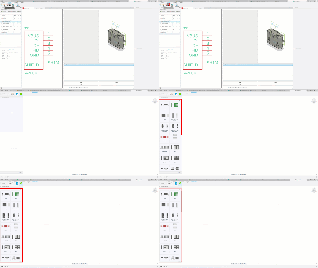
Selecting to use the package editor from the toolbar will now conveniently have the IPC compliant package generator available.
[icon name=”thumbs-up” class=”” unprefixed_class=””] Improved! Spline tool
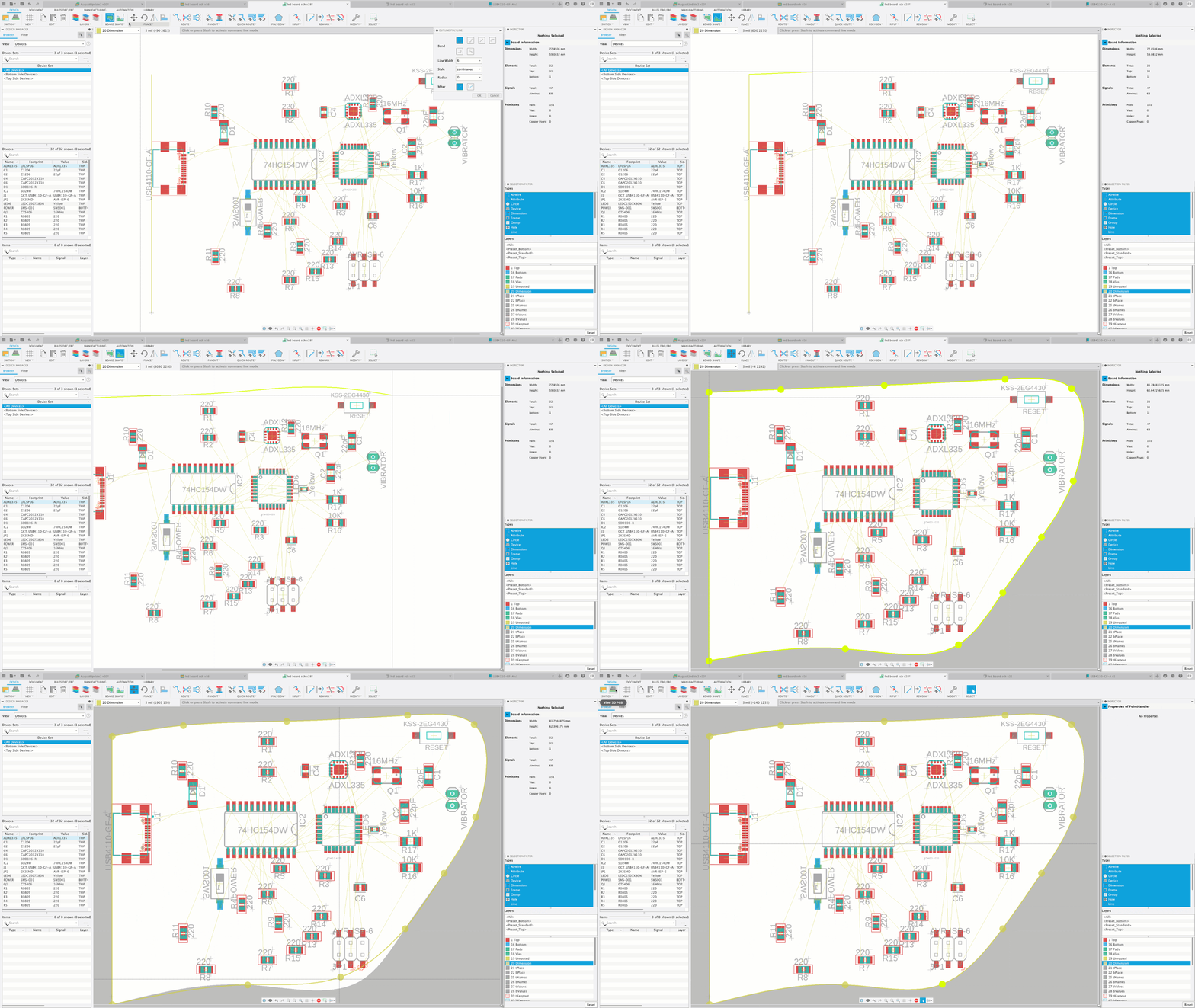
The Spline tool is fully supported in electronics environments. If you create the PCB outline using splines in Fusion 360’s sketch and send the outline curves to Fusion electronics, the splines will not be split into small line segments any more. Select the spline, it will now show the control points and the line handler.
[icon name=”thumbs-up” class=”” unprefixed_class=””] Improved! Reposition Attribute
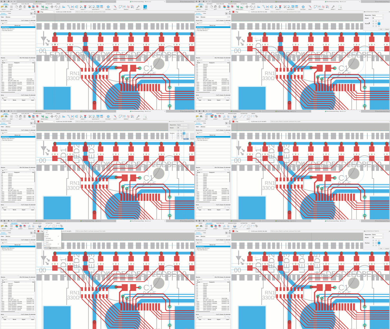
Now you will be able to access the reposition attributes options from the Document tab. Thanks sebastienSQA5P for raising this in the forum!
[icon name=”thumbs-up” class=”” unprefixed_class=””] Improved! Print
We have now added the print option to all Fusion 360 electronic environments (Library, Schematic, and 2D PCB). Hat tip to Shaberadda for also mentioning this in our Fusion 360 forums.
[icon name=”thumbs-up” class=”” unprefixed_class=””] Improved! Saving

Previously, if you save a schematic design with edits, PCB design or any related electronic editor wouldn’t save, even if it had new edits. With this update, saving in any of the electronic editors will cascade to all related editors to save if they have new edits. This update extends to the 3D PCB.
[icon name=”thumbs-up” class=”” unprefixed_class=””] Improved! Pin and Gate Swapping
File>New Electronic Design > Schematic Editor > Modify Panel > Pin Swap & Gate Swap
The action of pin swapping allows the designer to exchange pin within a component that have the same function. This exchange is desirable due to the position of the component in the PCB. The same action can happen with a gate. A gate will consist of multiple pins, components will have multiple gates which have the same function. For these gates, Gateswapping empowers you to swap with gates that have the same function. As stated earlier, this helps you to optimize the component on the PCB. This Pin Swap and Gate Swap were options only available in the context menu or the command line. These actions are now available in the Modify pull down menu.
[icon name=”star” class=”” unprefixed_class=””] New! Title block management
Drawings > Sheet Settings > Title Block > Hover > Change Title Block

Per popular request, we’re bringing you greater control over your custom title blocks with this release, adding the ability to both rename and delete them after creation. After locating your title block in the Sheet Settings section of the browser, hovering over it with your cursor will reveal a “Change Title Block” button. Click it, in order to open a new dialog where you can Rename, Delete, or switch between title blocks on a per sheet basis by activating the desired block in the menu.
[icon name=”thumbs-up” class=”” unprefixed_class=””] Improved! In-canvas buttons for Projected and Section view creation
Drawings > Projected View or Section View placement
One thing we’ve consistently heard from you is that the drawing environment just feels different from the rest of Fusion 360. Along with new feature development, over the last few updates we’ve been working to make the Drawings experience more consistent.
We are continuing this momentum by improving the creation experience for Projected and Section Views – now when you place a projected view or point along your section view line, you’ll see a green checkmark and rollback button next to your cursor, allowing for intuitive and quick commitment or reversal of a placement. Of course, if preferred, you can still use the ‘Enter’ key to end the projected view command or finish drawing the section line.
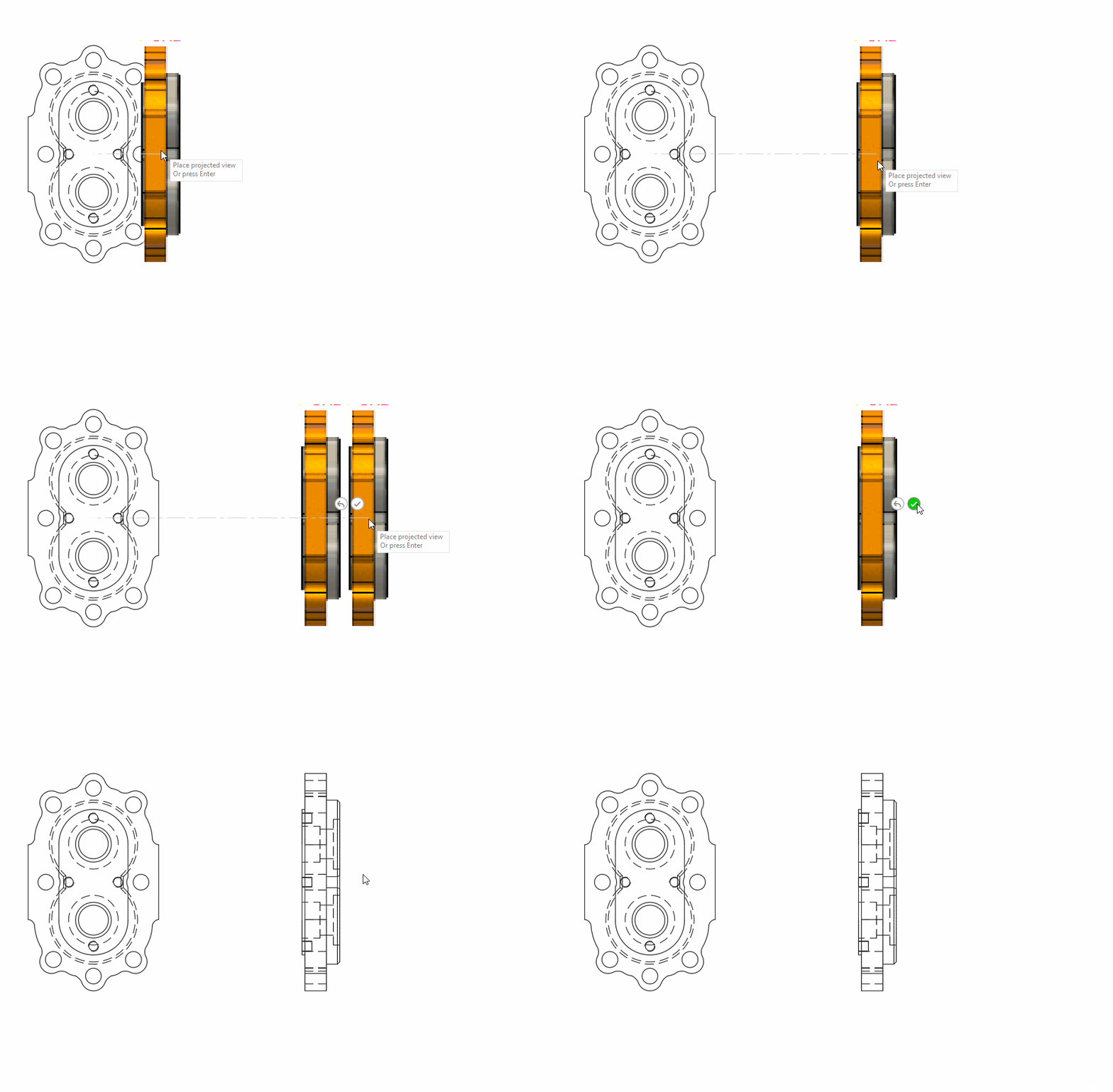
Projected View command completion with in-canvas button
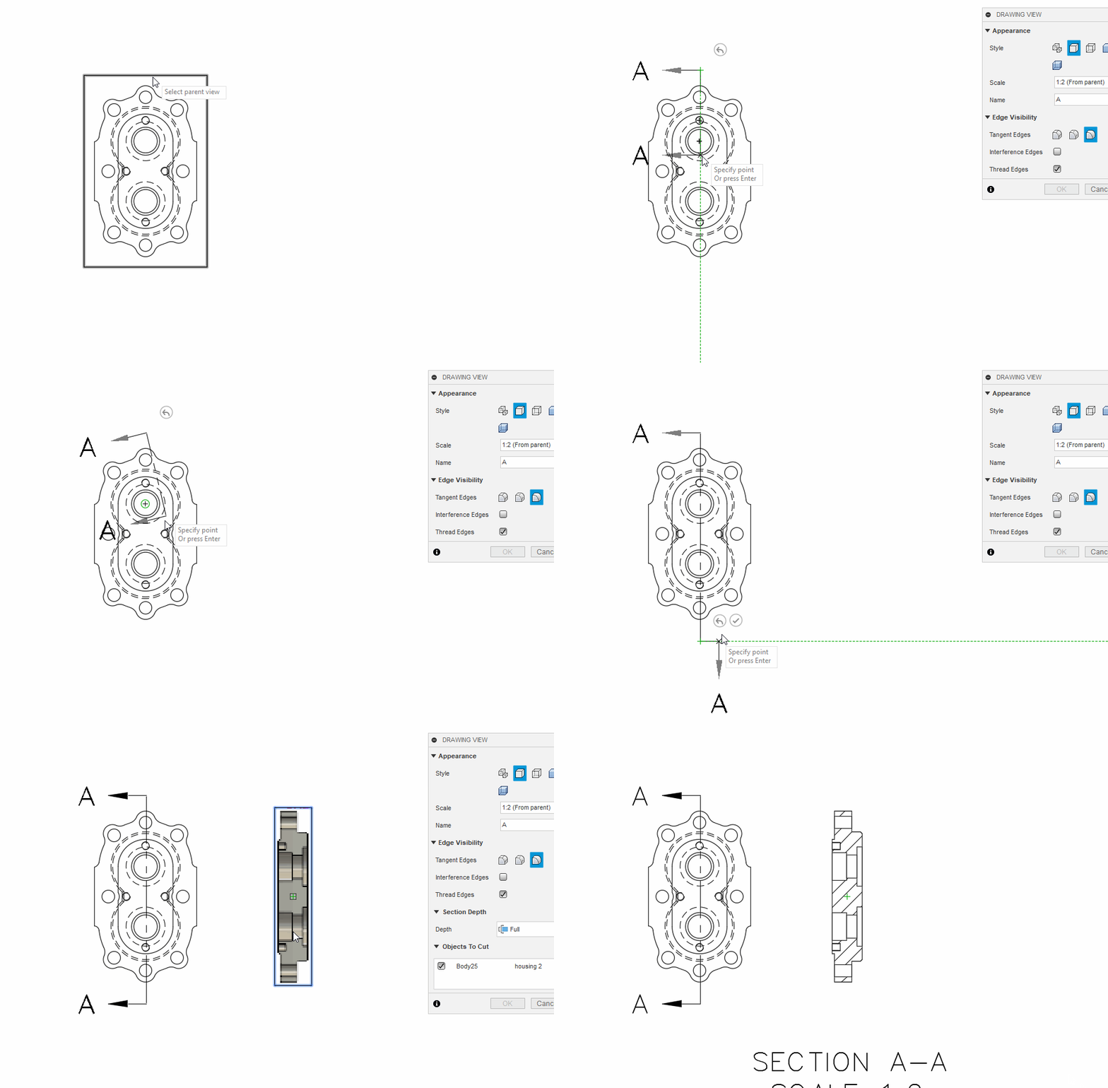
Section Line point rollback and completion with in-canvas buttons
Fixed: We sorted out some funky behavior triggered when component visibility is toggled while the Create Drawing dialog is open.
[icon name=”star” class=”” unprefixed_class=””] New! Manual Inspection
Manufacture Workspace > Inspection Tab> Manual Panel > Create Manual Inspection
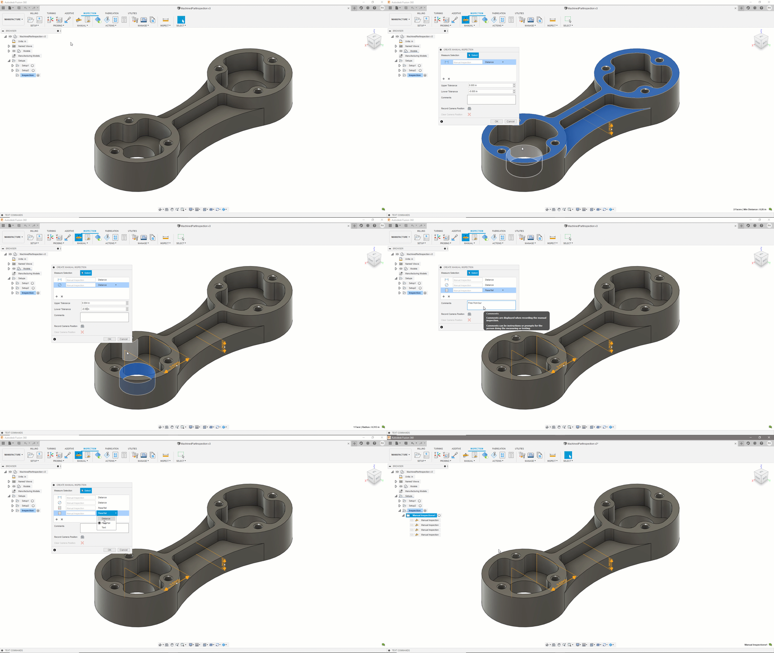
Dimensional inspection with manual measuring instruments, such as calipers, micrometers or height gages. Manual measurement has been enhanced significantly since the June preview and in addition to dimensional inspection also includes pass/fail tests (for example to record a visual check) and custom checks with text inputs (for example to record a serial number).
Record measurement results directly in Fusion 360 with a connected digital measuring instrument or by keyboard entry. Fusion 360 stores the results and calculates the deviations between nominal and measured values, and allows you to create an inspection report.
[icon name=”star” class=”” unprefixed_class=””] New! In-Process Stock Visualization
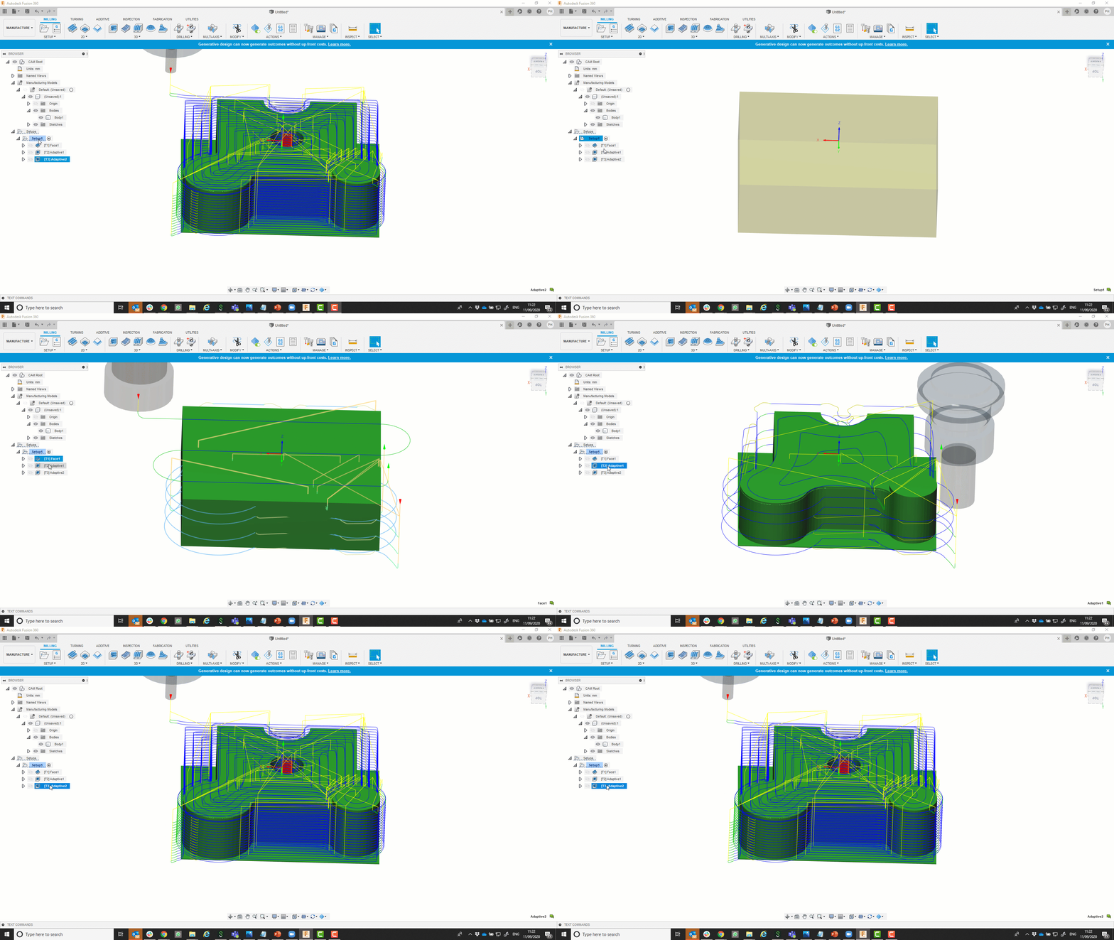
Click through the operations in the tree to see the resulting stock from all of the operations up through the one selected! Selecting an operation will show the stock result from simulation, without entering the simulation environment. Need more detailed simulation information? Entering the simulation environment with an operation selected will begin with the rest machining stock result from the previous operations automatically! No need to sit through the simulation of all of the previous toolpaths just to see the one you want.
In process stock also transfers between setups. Define the stock for the current setup as the result from the previous setup! Be on the lookout for enhancements in this area for moving the stock result to different component instances in a CAM Assembly.
[icon name=”star” class=”” unprefixed_class=””] New! Geometry-Based Invalidation
Making changes in the design workspace has always required operations in the manufacture workspace to be regenerated for safety. With this new preview functionality, geometry referenced for manufacturing operations is tracked and operations will only require regeneration for operations whose reference geometry has actually been changed.
[icon name=”star” class=”” unprefixed_class=””] New! Use Fewest Spot Drills Possible
Manufacture workspace > Hole Recognition > Options
Looking through the burdens of managing multiple holes in Fusion 360 and how to bring more efficiency to the hole recognition tool it was found that one of the biggest ways to save time and money on the manufacturing process is to use a single Spot Drill to center drill or spot chamfer varying hole sizes.
Instead of the user having to re-select a spot drill on each operation to reduce the amount of tooling needed we decided to take on the burden.
We built a checkbox that will allow us to look ahead at each spot drill operation and collect information needed for tool selection (minimum diameter, and tip angle if any has been modeled).
This means, If no chamfers are modeled we will use a single tool to spot every hole on the part using the largest spot drill that was captured in the template.
If there are modeled chamfers on holes, it is inferred to be the desired finished chamfer angle of the hole and Fusion will select the fewest possible but make sure to only use a tool with a matching tip angle for those holes.
[icon name=”thumbs-up” class=”” unprefixed_class=””] Improved! Remember Simulation Settings
Manufacture workspace > Actions Tab > Simulate
There have been a lot of enhancements in the Manufacturing workspace under the toolpath simulation. Having all those great options allowed programmers to find their best way to review the effectiveness of their toolpaths on the part. However, once you dialed in those toolpath simulation settings and closed Fusion they would be forgotten.
Fusion will now store those selected settings as defaults allowing them to persist across multiple sessions.
[icon name=”thumbs-up” class=”” unprefixed_class=””] Improved! No Dragging in Profile Roughing & Profile Finishing
Manufacture workspace > Turning Tab > Turning Profile Finishing > Passes
The option for No Dragging from the Profile strategy is now in the new Profile Finishing strategy. This is a setting used when turning hard or hardened material and the deflection force of the tool will be too great to make the typical cut up the wall. On the typical finishing path this path is usually fine but with harder materials burying the tip of the tool into the uncut stock can force the cutting tool back into the part causing an undercut area to put the part out of tolerance. Depending on the holder that you’re using this also may lead to the insert or part being pulled out.
No drag solves this by backing the tool off the wall and instead of ‘dragging’ the insert up the wall it finishes the wall with the insert traveling top to bottom.
This helps keep the force of the tool into the center of the insert for the entire finishing pass making sure your parts are within tolerance. Users can also benefit from this technology also being in Profile Roughing Strategies.
[icon name=”star” class=”” unprefixed_class=””] New! FFF: Color Legend for Toolpath Visualization
Manufacture workspace > Additive Tab> Actions Panel > Simulate Additive Toolpath
[icon name=”star” class=”” unprefixed_class=””] New! SLM: Machine and printer settings integrations
Manufacture workspace > Additive Tab> Manage Panel > Machine Library / Print settings library
If you have access to the Manufacturing Extension, you can also setup 3D prints for Selective Laser Melting (SLM) printers. In this release, we have added the Lasertech 30 SLM 3D printer from DMG MORI to the list of supported printers. This printer also includes a print setting with 50 micron layer thickness, so you can start slicing and generating toolpaths right away. We also added 2 additional print settings to Fusion’s library of print settings; one for EOS M290, and another one for Additive Industries MetalFAB.
[icon name=”star” class=”” unprefixed_class=””] New in Preview! FFF: Curved toolpath generation (G2 / G3 moves in G-code)
Manufacture workspace > Additive Tab> Print Settings Panel > Print setting Editor> G-code tab
This option allows Fusion 360 to represent curved geometry in models, not as a series of straight lines, but as actual arcs in the Gcode. So what are the benefits of using this option? Smaller Gcode files, less jittery movements and an overall improved surface quality. As this is still a preview feature, it is limited to Ultimaker and Prusa posts for the time being.
This is a big release for the API (although some of this actually snuck in last time for those of you really paying attention). See full listing of new objects and methods
[icon name=”exclamation-circle” class=”” unprefixed_class=””] Notice: Javascript API is being fully retired
We actually announced the end of support for the Javascript API a couple of years ago and haven’t been updating it or publishing the documentation. Without going into all of the details, it just wasn’t a long term solution that was going to work for the Fusion 360 desktop client. That said if you had any scripts or add-ins written in the old javascript API they do continue to run. Please note that as of the December release of Fusion 360 they will no longer run at all. We are making some big enhancements to the browser components that power things like Palettes, and it is no longer feasible for us to continue to support the old javascript interpreter we were using for that API.
PLEASE MIGRATE ANY EXISTING JAVASCRIPT API SCRIPTS OR ADDINS TO EITHER PYTHON OR C++ PRIOR TO DECEMBER 7,2020.
[icon name=”star” class=”” unprefixed_class=””] New! Support for Entity Tokens
This is a big one for developers using the Fusion 360 API. Previously, we exposed attributes on entities and many of you used this functionality to implement your own methods for tracking and managing ID’s of Components, Occurrences, Bodies, Faces, etc. The new API functionality introduces the concept of an entity token you retrieve from a given entity and then use that token to find the same entity in the future.
Attributes support adding named values to any entity and Fusion stores that information with the document. Attributes can be queried based on the names and values, which allow it to work as a naming mechanism but attributes allow you to do much more than just naming.
Entity Tokens are different in that they act as a permanent reference to a specific entity. Any entity that supports this capability will have the entityToken property. Calling this will return the entity token, for the entity. It’s up to you to save the returned token somewhere so you can use it later. The token is a string and can easily be saved in an external file or even in the Fusion 360 file in an attribute. To use a saved entity token, you use the Design.findEntityByToken method and if that entity still exists Fusion will return it.
One thing to be careful of when working with entity Tokens is that you should never compare entity token strings to determine if they represent the same entity. This is because it’s possible to get an entity token from an entity at one point in time and get an entity token for the same entity at a later time and the entity tokens might be different. However, when you use the findEntityByToken method the same entity will be returned for both tokens. So, if you need to know if two entity tokens are for the same entity, you need to use both of them to get the entities they represent and then check to see if the returned entities are the same.
[icon name=”star” class=”” unprefixed_class=””] New! Explicit B-Rep Creation
You now have the ability to explicitly define a surface or solid model. Previous to this, all models have to be constructed by combining a series of features, using temporary B-Rep functionality and the basic primitives and booleans it supports, and translating geometry from another source. With this new capability you can directly define the geometry and topology of a body. This is an advanced feature that will allow those that are computing surface shapes to directly create those surfaces instead of trying to recreate the shape with a feature. It also allows someone to create a translator that can import geometry from any other source into Fusion 360.
[icon name=”star” class=”” unprefixed_class=””] New! Ruled Surface API Support
We also added support for the creation and edit of ruled surfaces.
[icon name=”thumbs-up” class=”” unprefixed_class=””] Improved! Python and VS Code Authoring Experience
The integration with VS Code for writing and debugging Python applications has been getting significant enhancements over the past few releases, but with the last release we broke a few things… With this release we have got things back on track and made some major improvements. One is that we have migrated the python debugger from PTVSD to DebugPy which should allow a more stable environment in the latest MS Python extension and when running directly from VS Code. There were a few other issues related to running directly from VS Code that have also been addressed.
[icon name=”thumbs-up” class=”” unprefixed_class=””] Improved! CAM API
The CAM API has recently been extended to allow for more automation within the CAM workspace. The new objects, methods and properties have been added to the API along with several samples demonstrating the capabilities. Click here to learn more.
http://help.autodesk.com/view/fusion360/ENU/?guid=GUID-7F3F9D48-ED88-451A-907C-82EAE67DEA93
Some of the powerful new capabilities include:
Customer issues fixed
Learn more about what’s new in API
By clicking subscribe, I agree to receive the Fusion newsletter and acknowledge the Autodesk Privacy Statement.
Success!
May we collect and use your data?
Learn more about the Third Party Services we use and our Privacy Statement.May we collect and use your data to tailor your experience?
Explore the benefits of a customized experience by managing your privacy settings for this site or visit our Privacy Statement to learn more about your options.