SPICE Simulation Part 1: The Basics of SPICE and How It’s Integrated into Autodesk EAGLE
SPICE simulation is here! Autodesk EAGLE 8.4 brings SPICE in-house, allowing you to design and simulate in the same tool. Whether you’re a student or professional, SPICE will allow you to predict the behavior of your electronic circuits accurately. In this blog, we’ll be looking at what SPICE simulation is for the beginner and how to run your first EAGLE integrated simulation.
SPICE 101
SPICE is a computer simulation developed at the University of California, Berkeley. It’s one of the most widely used simulation programs that allows engineers to simulate the behavior of circuits. Why bother with simulating though? By testing how a circuit will perform in action, you can catch errors early in the design process before they manifest in your prototypes.
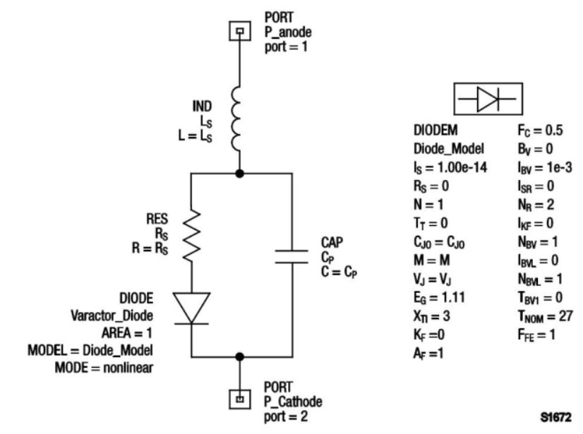
SPICE simulation makes this happen through the use of SPICE models and a netlist. The netlist defines how pins are connected on your schematic. Models contain text descriptions of a component’s values, which can then be used by the SPICE engine to simulate behavior mathematically.

Models for simple components can be simple one-line descriptions. Complex multi-part components will often have models with hundreds of lines of information. Unless you plan to use a library in EAGLE that already has spice compatible parts, then you’ll need to download SPICE models yourself. Thankfully there are plenty of component manufacturer who provides SPICE models to download on their website. Some of the most popular sources to check out for SPICE models includes:
| Vendor | Description |
| Analog Devices | Amplifiers and Comparators, Analog to Digital Converters, Digital to Analog Converters, Embedded Processing & DSP, MEMS and Sensors, RF/IF Components, Switches/Multiplexers, Analog Microcontrollers, Interface, Power and Thermal Management |
| Coilcraft | Power Magnetics, RF Inductors, EMI / RFI Filters, Broadband Magnetics |
| Directed Energy | Diodes, Switch-mode MOSFETs, HF / VHF Linear MOSFETs, MOSFET Driver ICs |
| Infineon Technologies | Fiber Optics, Microcontrollers, Power Semiconductors, Small Signal Discretes |
| Kemet | Surface-mount capacitors in aluminum, ceramic and tantalum and leaded capacitors in ceramic and tantalum |
| Linear Technology | Signal Conditioning, Data Conversion, Power Management, Interfacing, High Frequency & Optical |
| Maxim | Amplifiers and Comparators, Analog Switches and Multiplexers, Clocks, Counters, Delay Lines, Oscillators, RTCs, Data Converters, Sample-and-Holds, Digital Potentiometers, Fiber and Communications, Filters (Analog), High-Frequency ASICs, Hot-Swap and Power Switching, Interface and Interconnect, Memories: Volatile, NV, Multi-Function, Thermal Management, Sensors, Sensor Conditioners, Voltage References, Wireless, RF, and Cable |
| ON Semiconductor | Power Management, Amplifiers, Comparators, Analog Switches, Thyristors, Diodes, Rectifiers, Bipolar Transistors, FETs, Standard Logic, Differential Logic, |
| STMicroelectronics | Amplifiers & Linear, Analog & Mixed Signal ICs, Diodes, EMI Filtering & Conditioning, Logic, Signal Switch, Memories, Microcontrollers, Power Management, Protection Devices, Sensors, Smartcard ICs, Thyristors & AC Switches, Transistors |
| Texas Instruments | Buffers, Drivers and Transceivers, Flip-Flops, Latches and Registers, Gates, Counters, Decoders/Encoders/Multiplexers, Digital Comparators |
| Vishay | Manufacturer of analog switches, capacitors, diodes, inductors, integrated modules, power ICs, LEDs, power MOSFETs, resistors, and thermistors. |
Remember when searching for SPICE models that there’s a difference between PSpice and SPICE. PSpice is a proprietary simulator owned by Cadence, and many PSpice models are not compatible with standard SPICE simulators. To avoid any confusion, always stick to downloading SPICE3 (the latest 3f5) or SPICE2 models, as they are all versions of the good old Berkeley SPICE.
SPICE Simulation in EAGLE
The SPICE simulator in EAGLE uses Ngspice, an open source successor of SPICE 3f5. If you’re familiar with other SPICE tools, then the concepts and handlings of the simulator in EAGLE will be very familiar.
SPICE is fully integrated into Autodesk EAGLE 8.4, and there’s no need to install any additional software. We’ve also shipped a bunch of ready-to-use SPICE models and example projects for you to tinker with. During our time in this SPICE series, we’ll be working with the four available simulation types in EAGLE, which include:
- Transient Analysis. This method will simulate how a circuit performs over time as current travels through every component in your circuit.
- DC Sweep. This method analyzes the relationship between voltage and current over a given range for a DC input source.
- AC Sweep. This method analyzes changes in voltage and current in a given frequency range for an AC input source.
- Operating Point. This method analyzes the voltage and current for one or multiple components in a circuit at a single point in time. You can even extract and analyze specific component parameters.
Now that we have all of the basics covered let’s walk through some of the new SPICE features in EAGLE.
Simulator Path
Look at the directory options for EAGLE (Options » Directories from the Control Panel), and you’ll notice a new simulator path directory at the bottom. This directory is where the SPICE simulator lives and also contains some helpful documentation and release notes.

When EAGLE runs the SPICE simulator, it will reference this directory to find the Ngspice executable. You won’t need to change this directory path unless you’re using more advanced simulators.
One other thing to note is that Ngspice has a ton of capabilities for simulation outside of EAGLE. This means you can use the Ngspice simulator directly from your command line for a variety of other uses. Refer to the Ngspice Users Manual for more information.
Ngspice Library
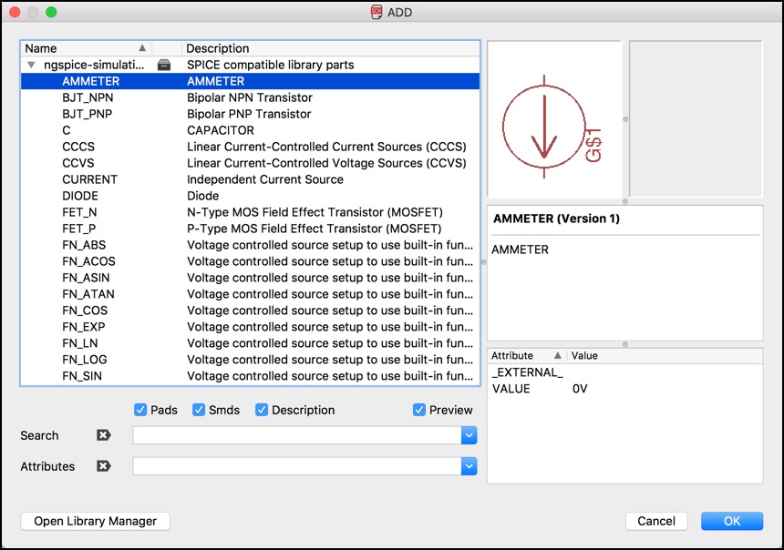
We’ve included a handy Ngspice managed library which contains a set of parts that are simulation ready. There’s everything from basic passive components like resistors and diodes to more advanced parts like BJT transistors, voltage controlled sources, and more. To check out all of the parts in this library, open your Add dialog and look for the ngspice-simulation.lbr listing.

One thing to keep in mind, if you don’t use parts from this SPICE compatible library, then you will need to download and map SPICE models to your schematic symbols. This process is beyond the scope of this blog, and we will cover in later articles but is relatively simple to do with the Map button in EAGLE.
Project Examples
We’ve also included a bunch of pre-configured circuit examples that will allow you to quickly test out the SPICE simulator without needing to configure settings. To find these examples, open your Control Panel, expand the Project folder, and look for the ngspice folder in the examples section.
All of these project examples are set up for different SPICE simulation methods. For instance, if you open opamp1.sch, this circuit will let you quickly test the AC sweep simulation without requiring any configuration. When you open this schematic, you’ll notice some new SPICE simulation buttons at the top of your interface. Here’s what each one does:
| Icon | Description |
| | Opens the SPICE simulation dialog. |
| Toggles the display of SPICE simulation results on your schematic. | |
| | Places new voltage or phase probes on your schematic. |
| | Map a SPICE model to an existing schematic symbol. |
| | Set SPICE device types and map SPICE models to either individual or multiple schematic symbols. |
| | Set up a voltage source on your schematic. |
Now that we have a handle on all of the new buttons and features, follow along with the steps below to run your first AC Sweep simulation:
- Open the opamp1.sch example from the ngspice example folder.
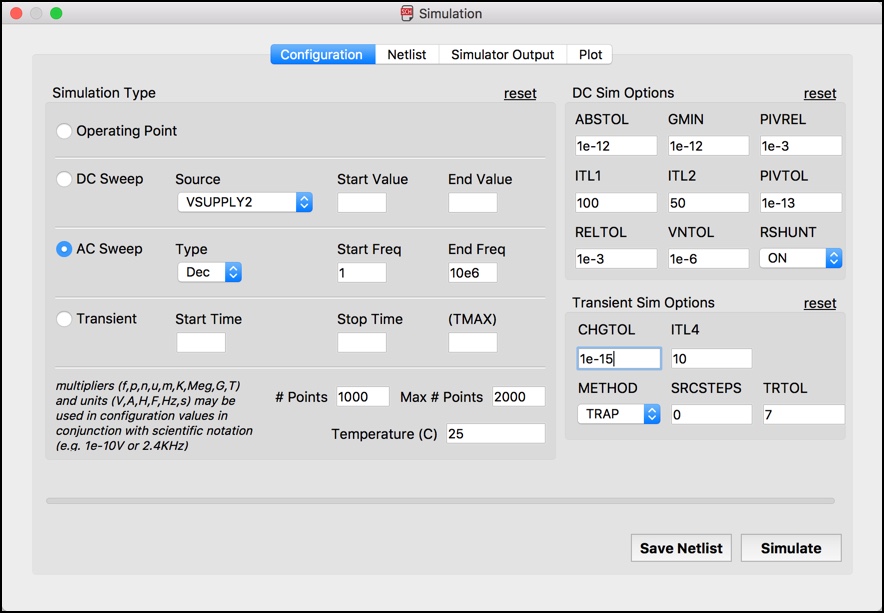
- Select the Simulate
 button at the top of your interface. This will open the Simulation dialog.
 - AC Sweep should already be selected with specific values entered for Start Freq and End Freq. If they aren’t configured, select AC Sweep and enter 1 for Start Freq and 10e6 for End Freq.

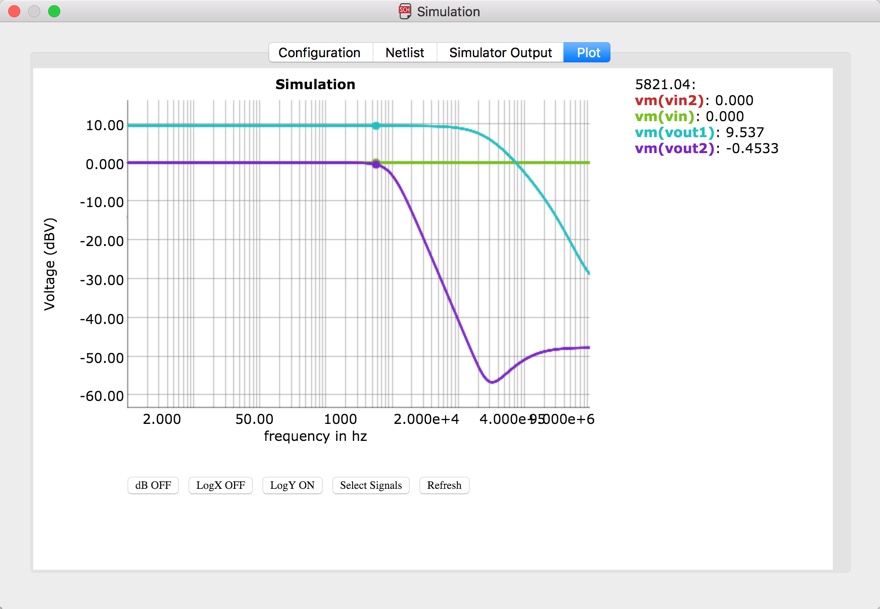
- Select the Simulate button to run the simulation, and you’ll be taken to the Plot tab.
All but one of the simulation methods (operating point) will show its results on the Plot tab. Here you can use your cursor to move left/right along the x-axis of the graph to investigate values. In this instance moving left/right will display the exact frequency value in the top right corner.

Running SPICE On Your Own Circuits
Before running a SPICE simulation on your schematic, all of your parts need to be mapped with SPICE models. To complete this mapping, you have several options:
- You can place parts that are already spice compatible from the ngspice-simulation managed library in EAGLE.
- You can download spice models from a component manufacturer like Texas Instruments and then map those models to your schematic symbols.
- You can create your own spice compatible libraries which involves making a schematic symbol, attaching a SPICE model, and mapping its pins.
We won’t be covering the intricacies of how to map schematic symbols to new SPICE models in this blog. Be on the lookout for future updates on how to convert an existing schematic to a SPICE compatible schematic.
All Spiced Up
We barely scratched the surface with all of the possibilities that SPICE has to offer for circuit simulation in EAGLE. If you want to dive deeper into the intricacies of Ngspice, take a look at the Ngspice Users Manual. Autodesk EAGLE 8.4 is setting the stage for some powerful simulation technologies in the future. We’ve started with the basics in this release, but expect more simulation features in the future as we continue to expand SPICE in EAGLE!
Ready to start simulating your circuits with SPICE? Try Autodesk Eagle 8.4 today!