Elevate your design and manufacturing processes with Autodesk Fusion
This post is also available in: Deutsch (German)
We’re excited to kick off our Machining Fundamentals series, created to help you brush up on your CAM knowledge, whether you work in a machine shop or are just getting started. Each episode is hosted by one of our in-house machinists and will provide a detailed overview of a tool/process. First up is an introduction to milling machines, where you’ll learn the basics of when and how to use a milling machine in your Fusion 360 workflow.
Milling machines are comprised of a spindle that holds a cutting tool and Workholding that holds the components. The spindle rotates and cuts the paths, while the Workholding holds the part. Our setup in this video features a large vise, but you can also have smaller vises that hold your part. All you need to do is make sure that your Workholding is suitable for the part. You can also have bespoke Workholding, or “soft jaws.” Soft jaws hold an individual part, and they are bespoke to their individual components. Working with a vise, however, is more universal and common in practice.
When it comes to different milling tools for milling machines, there is a lot of ground to cover. Below is a list of key tools we go over in this video:
Flat End Mill
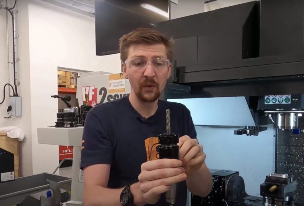
First we take a look at our Flat End Mill. This mill features straight flutes that are along the length of the tool, as well as a flat tip. Flat tips are really good for what we call roughing operations where a lot of material is removed very quickly. They produce nice, straight lines on a part on solid walls of components. However, it’s pretty restricted to roughing lots of material or finishing very straight walls on components.
Facing Cutter
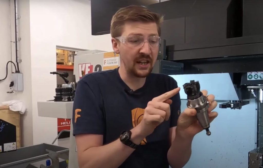
The Facing Cutter has individual tips that are screwed into its holder. The end mill we looked at before was just was solid tungsten carbide, whereas with this tool, the body of it is steel and its tips are tungsten carbide. The Facing Cutter produces a really high surface finish on flat faces.
Ball Nose Cutter
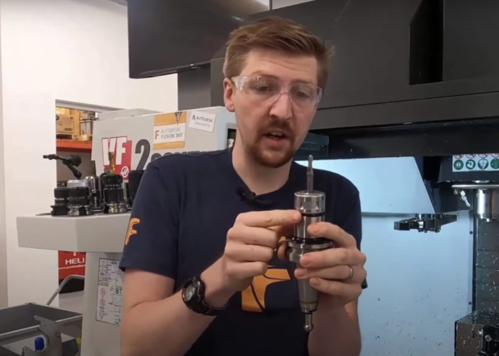
If you want to make curved surfaces, you use something called a Ball Nose Cutter. Ball Nose Cutters look very similar to the End Mill we looked at first, but rather than having a flat tip to it, we have a complete radius that goes all the way over. Ball Nose Cutters are good at creating complex free-form surfaces where they will go across the surface and produce a really nice finish. These can be low to do that, though. So we only normally use these for the finishing operations.
There are lots of other tool types, including drills and reamers. We can also have probes fitted to machines that help set up our component and inspection. But let’s move on to looking at our whole machine.
As you can see in the video, the machine we’re using started as a 3-axis machine with three linear axes—the X-axis that goes left to right, the Y-axis that goes front to back, and then the Z-axis that goes up and down. Let’s take a look at how we have added additional axes and converted this 3-axis machine into a full 5-axis setup.
We have bolted a trunnion to the original table of the machine. This allows us to add additional axes and make more complex, high-precision parts and reach different orientations. So I can move the A-axis, which is a rotary axis now. I could also move the C-axis, which is another rotary axis. So, now we have two additional axes bolted onto the table.
With the addition of the trunnion, this machine is now a 5-axis machine. It’s called a Table Table 5-axis because both rotary axes are on the table instead of on the machine’s head. If this head were to pivot and rotate, it would be called a Head Head machine. And as you might have guessed, you could also have a combination of a Head Table, where both the head and the table moves.
So far, we’ve covered multiple different tools and multiple different axes—all moving together in unison to create our components. So how do we actually make parts? Let’s take a look at some toolpaths inside of Fusion 360.
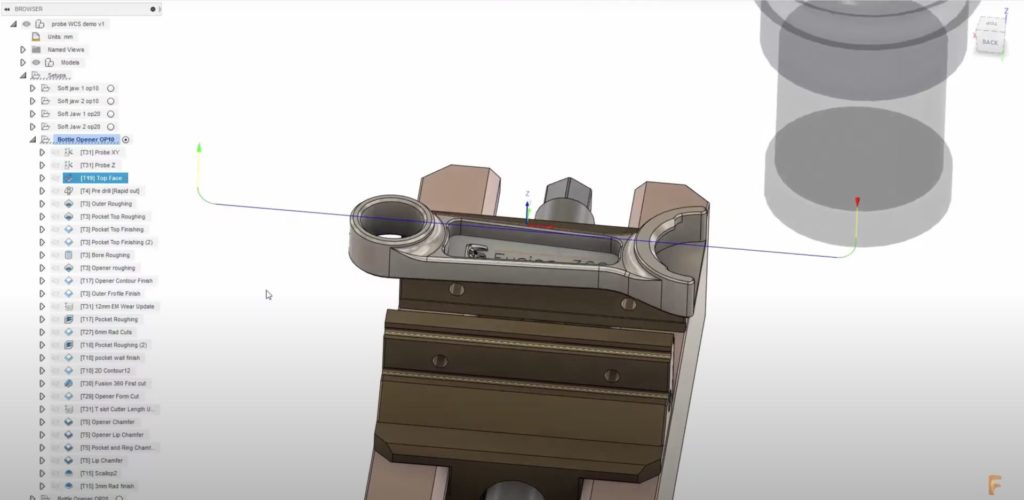
Within Fusion 360, we can see the path the tool will take, and the cutting motions are displayed in blue. From the main display, you can also look at further information, such as machining time, tool changes, and comprehensive toolpath analytics.
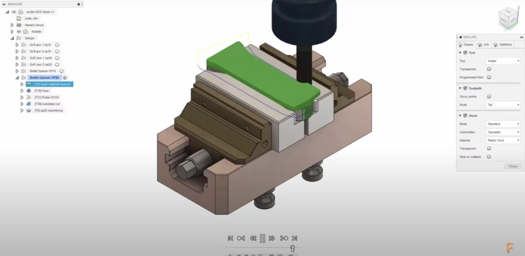
All the toolpaths are contained within the browser, and multiple setups can also be present within the same components. Having multiple setups allows you to machine both sides of a component. Once you have toolpaths created to machine the part, you can simulate the path they will take and look at the removal of the stock itself.
Stay tuned: following this episode about milling machines, we’ll be publishing Machining Fundamentals episodes weekly. Future topics include milling machine tools, lathes, post processors, toolpath types, NC code, work coordinate systems, and more.
In the meantime, download Fusion 360 to start machining smarter today. Learn more about how to maximize your machine with Fusion 360. Or, refer a friend if you’re already part of our community.
