Elevate your design and manufacturing processes with Autodesk Fusion
This post is also available in: Italiano (Italian) Deutsch (German) 日本語 (Japanese)
Learn why Fusion 360 allows for easy printed circuit board (PCB) design for industrial designers with ECAD and MCAD integration.

Industrial design is a shifting tide that favors innovation. As a result, CAD software, like Fusion 360, is quickly evolving and becoming more robust, allowing for easier printed circuit board (PCB) design for industrial applications. As this innovation progresses, the gap between industrial designers and PCB engineers is quickly narrowing. Instead of communicating across departments and working with one-way workflows, designers and engineers can collaborate within the same program. ECAD and MCAD integration saves time and money.
As with any advancing technology, it’s crucial that engineers fully educate themselves on PCB design before testing out the next big thing. Basic PCB design is fundamental for effective communication and collaboration.
Effective Communication
Industrial designers who understand PCB basics can communicate more effectively with PCB engineers. As with most professions, PCB design has its own anthology of technical terms. Understanding basic PCB terminology alleviates possible communication mishaps and improves team functionality.
Here are a few essential technical terms:
- Silkscreen — A layer of ink trace depicting white identifying marks like letters, logos, and PCB manufacturer symbols on the circuit board.
- Gerber file — A file generated during PCB design containing critical information about holes, traces, components, etc.
- Copper traces — Conductive tracks that connect components, pads, vias, resistors, etc.
- Design Rule Check (DRC) — Automation that checks physical board layout against a series of design parameters or rules.
- Via — A conductive hole between two correlating pads on different board layers. Boards can have several layers.
Successful Collaboration
The ease of collaboration was often taken for granted before remote working became increasingly common. With more remote collaboration comes the likelihood of communication breakdown, which can dissolve successful collaboration and stall an otherwise momentous project. With cloud-based software like Fusion 360, remote collaboration is easier than ever before. Collaboration fosters innovation, and innovation pushes the boundaries of what is known and what is unknown. A project team cannot expect significant progress if one or more of those involved is out of touch with basic PCB concepts.
However, it’s worth noting that collaboration is an ideal learning environment. Those who are currently taking PCB design courses shouldn’t be afraid to ask questions and gain hands-on experience whenever possible.

PCB Layouts and Schematics
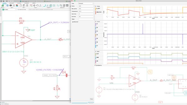
Printed circuit board design begins with a schematic. Fortunately, Fusion 360 contains many tools to help the user draw an intricate schematic. Users can utilize the component library to map a circuit diagram. At this stage of the design process, the circuit layout and electronic component placement can be altered to fit on the circuit board perfectly.
Once you perfect the electronic design, select the ideal substrate sheet to coincide with the circuit’s purpose. Then drill Via holes using a computer numerical control (CNC) machine. At this point, the circuit is now printable and ready for etching and stripping. Of course, a lot more goes into the PCB design process, PCB assembly, and PCB prototyping.
Knowing the design process optimizes self-integration into the larger PCB community and creates a cohesive relationship between PCB designers, engineers, and PCB design software.
Learn Basic PCB Design with Fusion 360 Today
Depending on experience and education, some up-and-coming industrial designers might be familiar with basic PCB design concepts. In any case, educational resources and tutorials are available to new and veteran industrial designers who want to refresh their knowledge of or learn about basic PCB design in tandem with the intuitive and integrated design capabilities in Fusion 360.
Connect your design and engineering today. Get started with a free trial today.
