& Construction

Integrated BIM tools, including Revit, AutoCAD, and Civil 3D
& Manufacturing

Professional CAD/CAM tools built on Inventor and AutoCAD
20 min read
Welcome to the first edition of Design Rewind! This series is all about tackling practical design challenges to sharpen your engineering skills. To kick things off, I want to focus on a topic that’s everywhere in embedded systems nowadays, sensors. Whether we realize it or not, we all love sensors. Why? When done right, sensors turn ordinary products into those supernatural gadgets that enable our efficient, smart, connected, and fun future!
Sensors are all around us. They’re in your new car with the state-of-the-art automatic parallel parking system, or the smartphone in your pocket which uses GPS and digital compassing to tell you how to get to the store. Consider also the smartwatch on your wrist that tells you your average sleep time is a bit off today. Sensors make ordinary electronics compelling and truly useful.
Let’s take a look at an example application area, the sensors required, and some considerations for the embedded system and interface circuits involved.
|
Ambient Light Control Let’s suppose we want to have our product respond to the ambient level of light and perform some action. This is a common feature in products today. One example we are probably all familiar with is the “automatic” setting for brightness on our smartphones. On one popular phone model, if you watch carefully, the phone will increase its brightness when you go out into bright sunlight, and decrease it when you come inside to dim indoor light. Why does it do this? In dim light, too much brightness and contrast are uncomfortable on your eyes. In contrast, when you go in the bright afternoon sun, your phone has to crank up the brightness of your screen or else you won’t be able to see it. You can see the difference when you set the screen at a fixed brightness level and test in these two different lighting environments. |
You might be wondering, “how does my phone do this?!” Let’s consider several possibilities:
While these are all valid (although not ideal) options for implementation of ambient light control, this is not typically how it is done. If you look closely, on many phone models, you can see the small sensor, just under the glass on the top face of the phone. You will see a sort of “keep out” area where the glass is thinner and in a perfect circle shape – that is where the sensor sits, likely under what is called a “light pipe.”
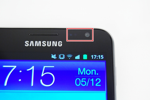
These sensors are so prevalent today that a quick search on a part distributor’s website for active, ROHS compliant, ambient type optical sensors yield 250 results. For light pipes, there are over 600 results. Let’s pick a sensor for our design challenge to understand what parameters we need to be aware of.
Choosing a sensor is where the design process starts. At this point, you haven’t drawn up any schematics, designed any circuits, or written any firmware. However, choosing your sensors properly for the end application requires thinking about the whole system, at least in a rough, first-pass manner. Of course, your system will be iterated on and fine-tuned as you go from prototype to your final production electronics.
Your final choice will likely be different from the first, but you want to minimize the amount of redesign you need to do. For example, if you can avoid it, you would rather not change sensors after boards have been manufactured, and after system firmware has been written. This results in lost development time, and time is money.
Sensors come in all “shapes and sizes” and choosing one over another could have significant implications in power, area, cost, performance, development timelines, and ultimately, the success of your product. Consider these factors:
Some additional considerations:
If the hardware or firmware engineers have a standard microcontroller they prefer to use (for whatever reason), would it make a difference if it has an 8-bit A/D vs. a 12-bit one? What if there is no microcontroller?
What if there is a very specific analog voltage output range in mind that you need to interface to another sub-system? Do you need to find one that exactly matches the output, or can you translate the output using an interfacing circuit to get what you need?
This is just a sampling of relevant questions, but the point is that the choice of a sensor can have wide implications, from technical system design to product-level performance and aesthetic design issues. To help make your selection process more straightforward, consider these tips:
 Tip #1: Always consider the overall system integration when choosing sensors.
 Tip #2: Understand the end-application use-case clearly and precisely.
 You need to be able to translate high-level product requirements into the technical specifications you use when choosing sensors. Many times the sensors in a product are tightly coupled to the device’s main features, and choosing the wrong sensor can actually kill your product. Consider a device that has a proximity sensor, and it works perfectly when the user is 1 inch away but fails at 2 inches where the application actually requires a proper response. Or a temperature sensor that works perfectly but has a response time of 10 seconds, and the application requires less than 1-second response. These sorts of oversights are common for beginners and can make or break your product.
In our ambient light sensing example, if I were to tell you that the product was to run on a standard lithium coin-cell battery vs. a large rechargeable one like in a smartphone, would it make a difference? What if you need a very high sensitivity to sense precise ambient light changes? What about response time, suppose I need this device to respond within a few microseconds vs. a few seconds? You need to understand the requirements of the end product exactly and make sure you include some buffer in the design so that if these requirements expand a bit, you are not out of luck.
 Tip #3: Know the standard variations and variables involved for the given type of sensor and available orderable devices.
 Most sensors will have some sort of measure of sensitivity, sometimes expressed as such, or expressed as some output unit (voltage, current, etc.) vs. an input unit (temperature, pressure, force, etc.). Sensors sense something from the external world, and if your sensor datasheet does not express its sensitivity (or it is not painfully clear to you) regarding output/input, you better go look for another manufacturer’s part. You need to know this, and you don’t want to have to spend a great deal of time trying to wrangle this information out from the manufacturer’s documentation.
On the other hand, there are some specifications that are not important, or given the type of sensor and its intended use, are more or less fixed and not even stated on the device’s datasheet. For example, hysteresis may be critical for a pressure sensor and its related application, but might not be present in the datasheet for a different type of sensor. Why? For the technology involved, it’s known to be a negligible factor, or there is no physical basis for it.
Keep in mind that typically the more sensitive, the faster the response, the more output options available, the smaller the size, the lower the power, the more expensive the part is.
A good place to get a baseline list of parts you can actually use is to search on a distributor’s website that lets you filter for a variety of variables and manufacturers. Personally, I love using Digikey because their search gives a ton of parameters you can filter, including in stock, ROHS compliant, package type, cost, and more.
 Tip #4: Choose a sensor that has specifications that exceed your actual end requirements.
A good rule of thumb is to design in some percentage, say 30%, or more of the product requirement into the system, in case your requirements change as the design evolves.
For example, if you need a response time of 1s, find one that can give you the same output in <= 700ms. If you need a sensitivity of X / Y, find one that can give you X / (0.7 Y). Always design in some buffer into your system. Keep in mind, sometimes one specification is related to and affected by another, or depends on specific device configurations. You always need to keep all parameters in check.
 Tip #5: Make a spreadsheet of your options and do a comparison based on relevant parameters.
 These parameters can include variables like performance specifications, area, cost, or any other parameter that is of interest for your system and application. I like to keep a spreadsheet of various options for multiple reasons. Performing this step explicitly forces you to do a quick, up-to-date survey of what is available in the space. For example, via a selected few, top tier manufacturers, or via a distributor database (relatively manufacturer independent).
This is not really a required task in your design process, but how can you be sure if you made an educated choice if you haven’t surveyed what is currently available? Remember, the world of sensors changes quickly, and what was available 6 months ago may not be available today, and there may be new devices you didn’t know exist.
This document is for you to know (with evidence to back it up) that you made a good design decision, and in case you need to show others you did your due diligence in analyzing the requirements and making an optimal choice given the parameters you’re working with.
 Tip #6: If other constraints permit, choose a sensor with onboard conditioning circuitry.
 We will get to sensor signal conditioning circuits in another follow-up post, but if you can afford the size and cost, try to choose a sensor that already conditions the transducer output for you, with compensation and conditioning circuits inside the package. There are many considerations that you need to be aware of with “raw” sensors, such as temperature variation, amplification, offset, and more, that have already been well studied, and handled appropriately in sensors that include these critical circuits. Sometimes it is not possible, or sometimes you really need a custom conditioning circuit, but if at all possible, don’t reinvent the wheel! Use a sensor with the conditioning, offset, amplification, and other circuitry built-in.
Chances are the IC a manufacturer developed over many years has been thoroughly tested and proven in hundreds of production products. This is a better option than anything you can kludge together in the extra research month you were able to get approved for yourself. At the end of the day, you’ll reduce design time and increase performance by going with a proven set of circuitry. That does not mean a system on chip (SOC) or another type of integrated solution is always best, however. Many times sensors that include conditioning circuitry also include more and more features that you may not need that cost you power, and so you have to optimize these trade-offs constantly and carefully.
With all our selection guidelines out of the way, it’s time to start making some assumptions about our design constraints.
|
Given these constraints, I did some research on Digikey and ended up with a filtered list of parts from which I chose the AMS TSL25xR series “light-to-voltage” optical sensors.
This device has a photodiode and transimpedance amplifier built into a small through-hole or surface mount package. We will choose the TH package and the TSL250R version just for simplicity (it is the most sensitive option in the series).

There are several pieces of information we need from the datasheet, let’s start by highlighting some basics:
Now, we need to check a couple of the plots:

This plot is important because it shows the output voltage vs.input light levels for the various device versions, all with VDD=5V.
What you may be wondering is how to relate this input light level to light levels in your application. For example, how can you relate bright sunlight to uW/cm^2?
This is typically done through calibration, which we will discuss in Part 2 of this series. For now, let’s just assume that direct bright sunlight corresponds to the max input on the plot.

This plot is important because it tells us what maximum output voltage to expect based on VDD.
If we connect the output to an ADC, this will directly correspond to the maximum value as a binary number to expect in the ADC results.

Finally, we have a plot of supply current vs. output voltage.
This is important since we need to know, given some VDD and input light level, what output voltage to expect and what current to expect. From the plot, we can see that the maximum current will be around 1.43mA.
That’s about it for specifications, let’s go back to our application and start designing in parallel. We will first need an EAGLE device (symbol and footprint combination).
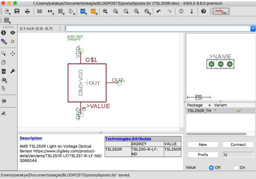
In EAGLE, make a new library or open your existing one, and click on the Add Symbol button in the Library Editor. Name this new symbol: TSL250R.
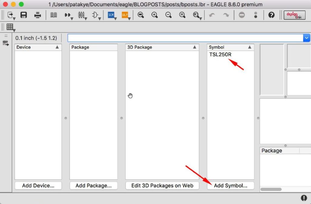
Since the device has GND, VDD, and OUT pins, add 3 pins and name them as such. Also, add the special values >NAME and >VALUE so that when the symbol is placed in the schematic, it shows the appropriate variable values.
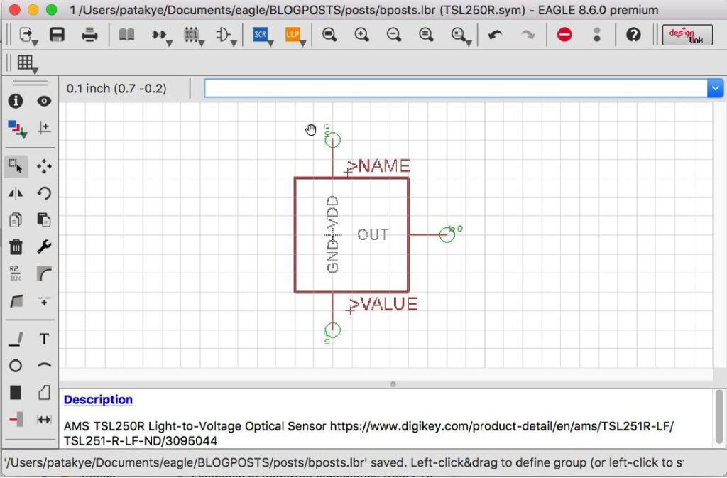
I also added a description including the distributor link, which I find useful. Once your pins and labels are complete, save the symbol and go back to the library Table of Contents (TOC).
Now select the Add Package button to add a package called TSL250R_TH (TH is for “through hole”). The device has 0.47mm diameter leads spaced 2mm apart.

In EAGLE I placed 3 through hole pads (vias), with a diameter of 1.016mm and a drill size of 0.6mm. This should fit just fine. Be sure to set your grid to 1mm so you can easily space the vias out.

Name your pads GND, VDD and OUT following the diagram in the datasheet, and add the >NAME text object so the part reference shows in your layout.
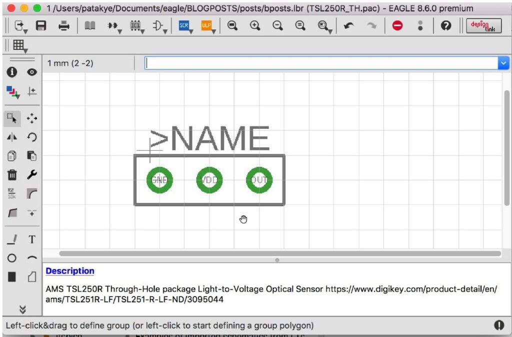
Now save the footprint and go back to the library TOC.
Select the Add Device button to add a new device called TSL250R. Add a description, place the symbol you just created, and on the right side click New to add the footprint you just made. I also set the device prefix to “U” so that when the symbol is placed the reference starts with this character.

Next, press the Connect button and connect the symbol pins to the footprint pads.

Back in the device editor, I added a few attributes – VALUE with a value of TSL250R, and Digikey, with a value of TSL250-R-LF-ND. At this point, the device is done, and you can save and close the library editor.
In your schematic, place the new part. Below you can see I also added a load output resistor per the device datasheet, and a connector that I will assume will bring in my 5V VDD and GND. The output from the sensor is connected to an ADC channel on the microprocessor, and SPI signals are connected from the micro to pins on the connector (we assume the display is SPI).
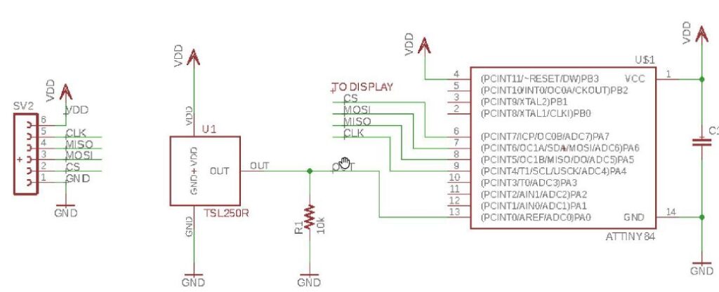
Here we have the basis for a simple system, where the ambient light sensor and microprocessor run off 5V, the microprocessor reads the sensor output via an ADC channel, performs some calculation, and then communicates with a display over an SPI interface.
For the board layout, I just placed the footprints and ran the autorouter with a 12 mil min size for traces. The board is so simple at this point that there’s nothing to worry about. The layout is not optimal since power is daisy-chained to the various parts, but we will ignore that in this post and get to layout techniques in another article.

Note that for this type of sensor, placement of the sensor itself is critical for good operation. We are using a through-hole part, and we want to place the part in such a way that the lens on the sensor will capture light in our final end-application.
To make the design simple, let’s just suppose we have a plastic box, and the sensor will view the ambient through a hole in this box. That is a very rough requirement, but we will go with it. If you are working on a team with mechanical engineers, you need to discuss the placement of the sensor as it relates to the actual electronics housing.
We’ll be making the housing in Fusion 360 to show how the part can be placed correctly.
For this application, we are going to make a simple box with cutouts for the sensor and electrical connector. Here are the steps we need to take:
Fortunately, with the new Fusion 360 integration for EAGLE, this is all really simple to do.
To do this, open your library in the Library Editor and select the Edit 3D Packages on Web button. This will kick off the conversion process for this library and turn it into a Managed Library.
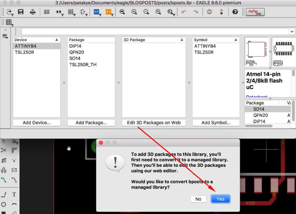
Once converted, if you used parts from libraries where 3D models were already mapped, then the 3D Package column should fill in with those models. Otherwise, you will get default models that can be adjusted in the editor.
A quick search on GrabCAD for “ambient light sensor” resulted in this model for the TSL235R.

After uploading the STEP file and positioning it properly, it should look like the image below:

Similarly for the SO14 microprocessor package:

Be sure to save a new version of the part when you upload and position the model, and save a new version of the library after updating each part.
I did not like the attached 6-pin female header part from the con-lsta library so I imported it into my library and added my own model. This had to be done in my own library since you can’t edit someone else’s Managed Library.

Now we need to update our library in EAGLE which we are using for this project, and that contains these parts. Open the Library Manager, choose your library, and select the Update button in the In Use section.
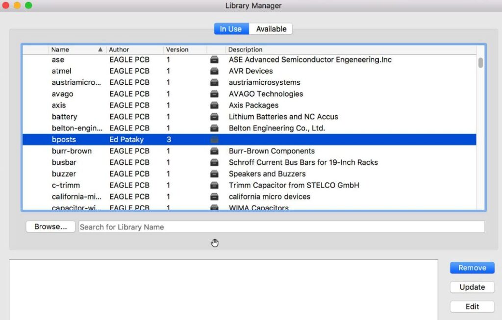
After this, I like to go to my Schematic Editor and select Tools, Update All to update my design. This synchronizes your design with the libraries it is using.
All parts should now have 3D models and we are ready to push to Fusion 360. In the Board Editor, select the Fusion Sync button on the right-hand side and choose to push to a new or existing project.
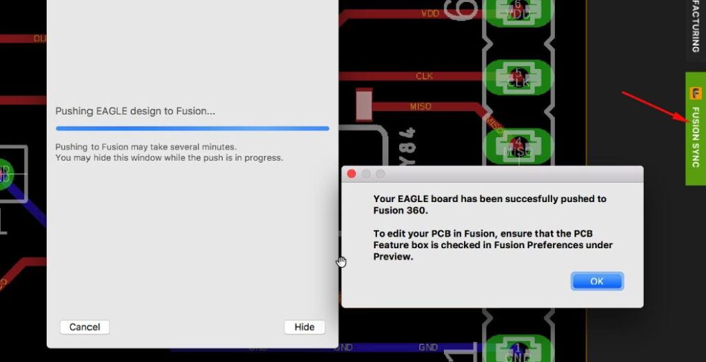
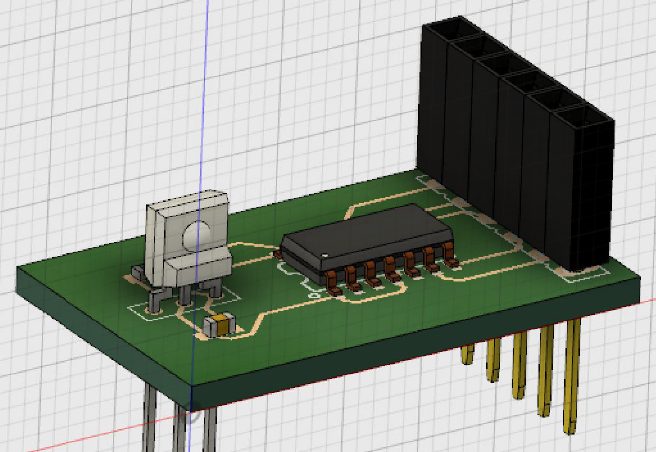
Now let’s create an assembly and housing for this board. In Fusion 360, I like to make a new design, and add a component for the housing (called “HOUSING” in the image below), and another for the board (called “PCB”), then import the board with the “PCB” component in edit mode. This will bring the EAGLE board into the PCB component in this assembly design.

Now edit the housing and sketch out a simple box, with some opening for the sensor and the 6 pin header to stick out.

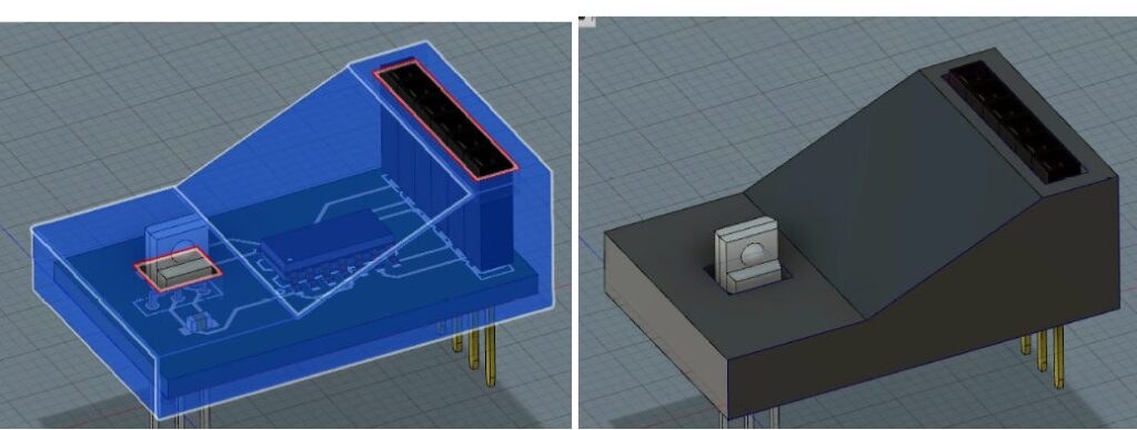
Below you can see some very basic plastic housing drawn around the board, with cut out holes for the connector and the sensor. This is the prototype gadget with the ambient light sensor.
This system configuration is simple and fairly straightforward, but getting it to work properly in the end-application will require a bit more work. We’ll be refining this design in a future post.
At this point, we’ve successfully constructed our first prototype design for an ambient light sensor device. As you can see, there are a ton of design considerations to make when choosing a sensor, and that’s just the beginning. In this simple example, we needed to make library parts, schematics, and layout a simple printed circuit board. We created a simple embedded system using an ATTiny microprocessor, a couple passive components, a connector, and sensor. With the electronics out of the way, our design headed over to Fusion 360 to construct a housing.
Keep in mind; this entire process was done seamlessly without having to swap and share design data with STEP files. With just a few simple clicks we were able to share ECAD and MCAD information with no interruption to our workflow. Fusion 360 Integration makes some wonderful things possible!
In upcoming installments in this Design Rewind Series, we’ll be taking a look at calibration concepts, processor code, circuit simulation, and more. Stay tuned!
Ready to design your own electronics device with sensors? Get started with an Autodesk EAGLE Subscription today!
Go forth and make things!
Ed Pataky – Autodesk Eagle
[:o>-<
By clicking subscribe, I agree to receive the Fusion newsletter and acknowledge the Autodesk Privacy Statement.
Success!
May we collect and use your data?
Learn more about the Third Party Services we use and our Privacy Statement.May we collect and use your data to tailor your experience?
Explore the benefits of a customized experience by managing your privacy settings for this site or visit our Privacy Statement to learn more about your options.