& Construction

Integrated BIM tools, including Revit, AutoCAD, and Civil 3D
& Manufacturing

Professional CAD/CAM tools built on Inventor and AutoCAD
23 min read

———
July 26, 2021 | V.2.0.10564
Usability
Stability
Manufacturing
Mesh
Electronics
Coming Soon | Injection Molding Simulation in Fusion 360
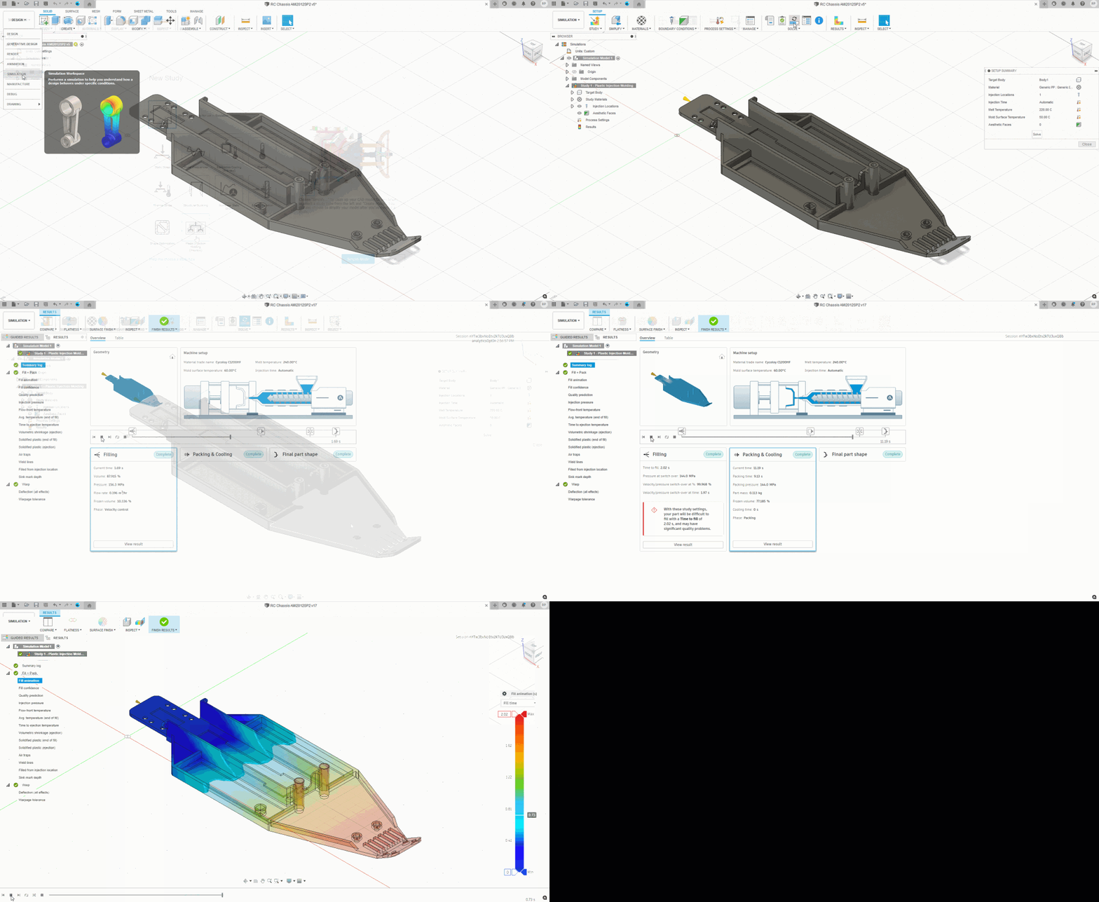
The August release of Fusion 360 will see Plastic Injection Molding Process Simulation added as a new Analysis Study to the Simulation workspace in form of a Technology Preview, with the intend to help Engineers understand feasibility of Injection Molding a plastic part and to understand the overall quality of the product, before the design stage is finalized. Avoiding problems in the design phase can avoid issues later in the production process when most solutions are costly and/or time consuming.
———
July 13, 2021 | V.2.0.10446
Recent Data Panel Fix
veso58S5W told us about an issue relating to the population of the Recent Data panel, we have addressed this issue, however, since this is a forward fix, only from this build onwards will the most recent data correctly start populating the panel.
Extrude Fix
We fixed an issue reported by EKMS where the extrude command automatically fills in the last used value as default instead of the default zero.
“Could not open file” Error / “Corrupt File” Error issue Fixed
Some of you have reported that you were unable to open certain designs after the latest update with a notification of corrupt designs. Sorry for this – we got a fix out which should eliminate this issue.
———
July 6, 2021 | V.2.0.10440
New! Korean and Spanish languages now supported
User Profile > Preferences > General > User Language
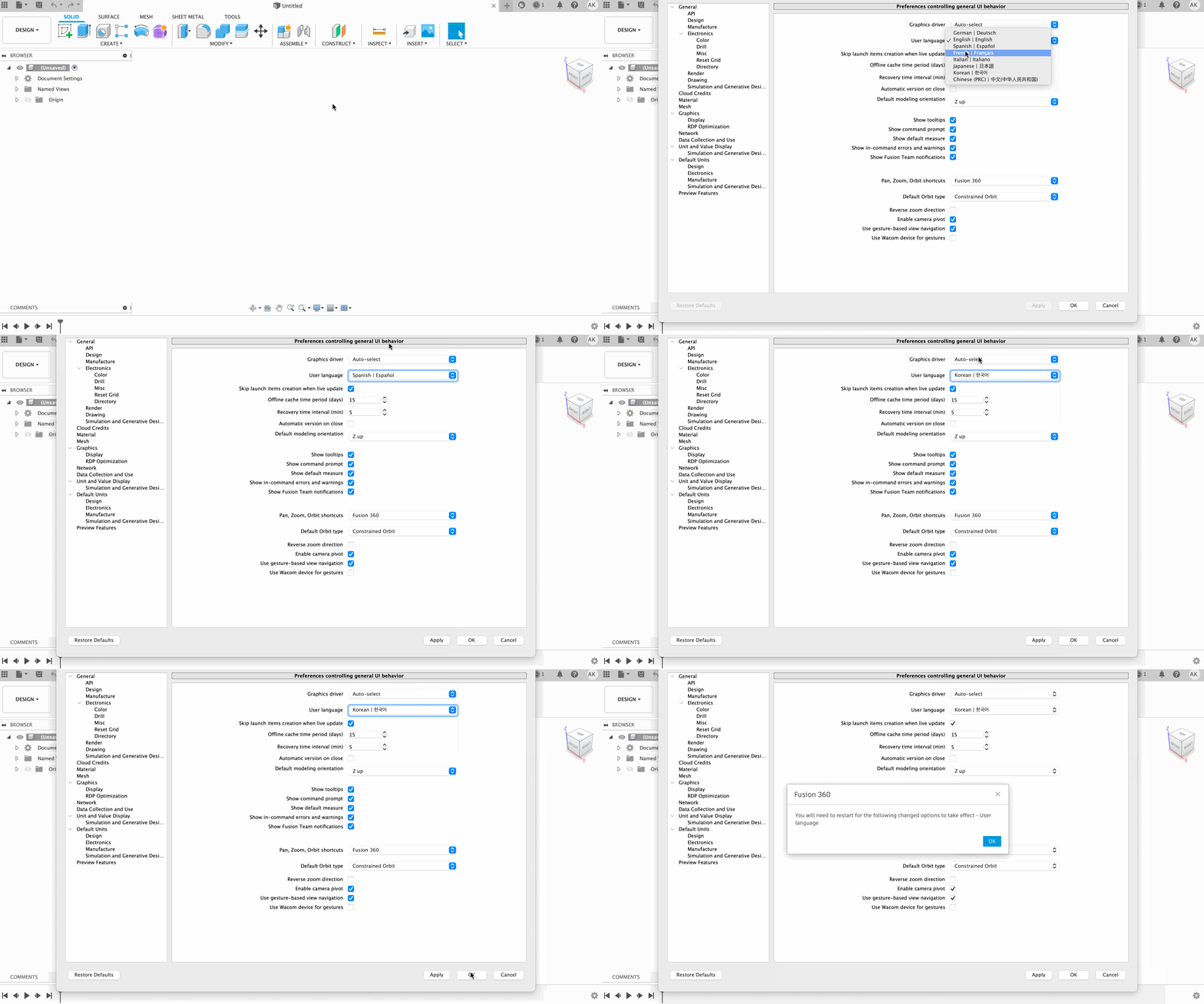
Korean and Spanish speakers rejoice! You can now run Fusion 360 in either language by switching to them from your User Language settings in your Preferences. Please note that once you’ve changed your language setting in your Preferences, you must restart Fusion 360 in order for the new language to take effect. Fusion 360 now currently supports eight official languages: English, German, French, Spanish, Italian, Chinese, Japanese, and Korean.
New! Fusion 360 icons for macOS Big Sur

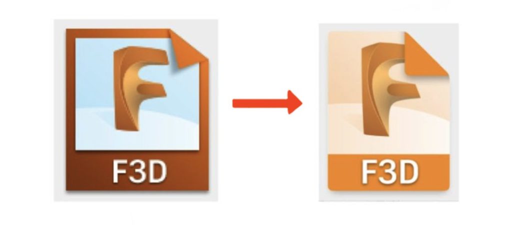
We’ve updated the Fusion 360 application icon as well as the document icons to align with the latest macOS visual style standards. The image below shows what the previous F3D document icon looked like to the left, compared to the updated one to the right. Things should look a little more cohesive now.
New! Mesh environment (out of preview)
Design Workspace > Mesh Tab
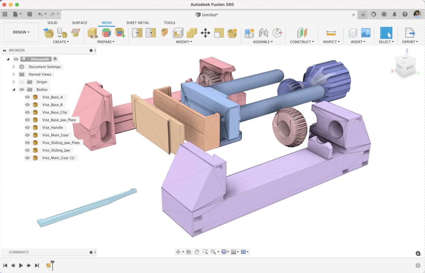
It’s official – the Mesh environment has graduated from preview functionality and is now a persistent tab within the Design workspace. We’ve completely overhauled the toolset, improved the performance of how you edit mesh bodies, and added a few new tools to increase flexibility. Working with mesh bodies in Fusion 360 has never been better, and it’s now available to everyone.
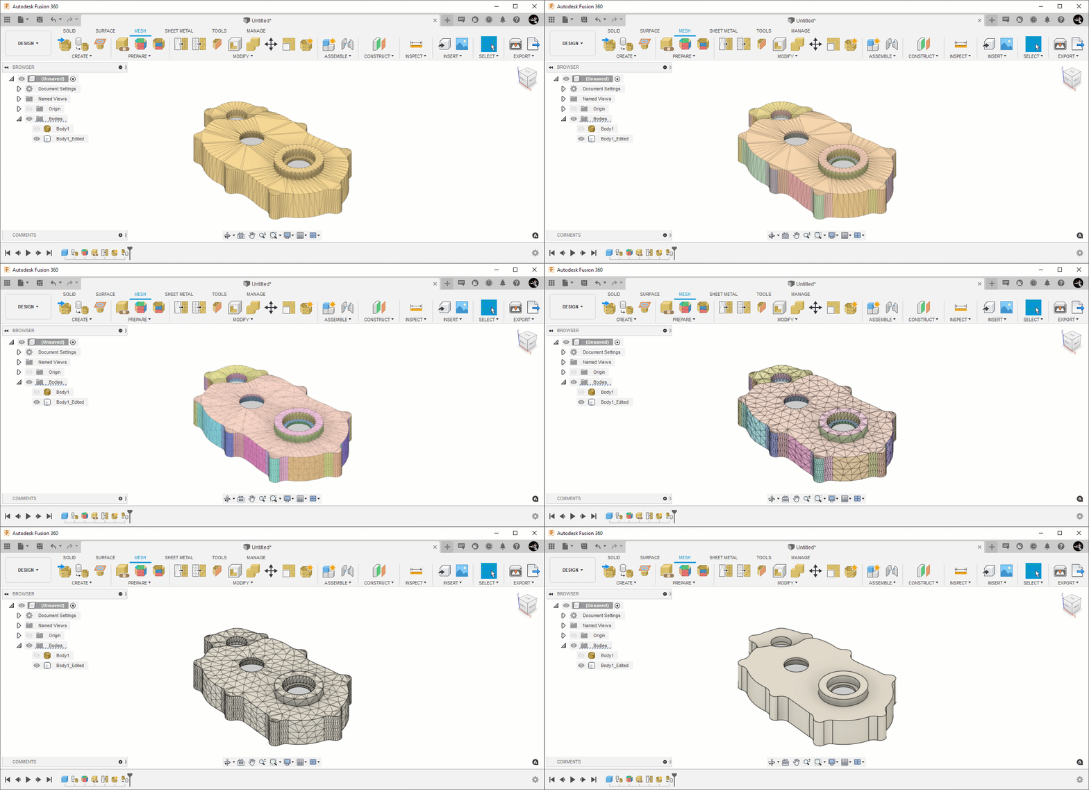
Traditionally, working with mesh bodies such as STLs and OBJs has always been isolated and disconnected from the CAD world. As a consequence, this often led to errors and data loss with little to no opportunities to undo/redo a committed action. There was also a lack of interactions between BREP and mesh bodies, but Fusion 360 now changes all of this by providing a history timeline to your mesh edits as well as improved conversion options. Here are top 6 things to know about the new Mesh environment:
1. Seamless interaction between Solid & Mesh
Open STLs, OBJs, and 3MF files all at the same time, in the same canvas. CAD and mesh bodies can now coexist within the same environment. And yes, inserting a STL will also let you define the mesh’s units.
2. Parametric editing and Timeline
Meshes now have a parametric history and face group information similar to face information for Solid models. Actions can be undone, redone, and edited via the timeline.
3. CAD-like interaction with meshes through full control over face groups
Intelligent meshes (face groups) enables you to make quick and easy changes.
4. New mesh-to-solid conversion options We’ve expanded on how you can convert mesh bodies into usable solid bodies with options like Faceted conversion, Prismatic conversion (available in paid, startup, and education offerings), and Organic T-Spline conversion (coming soon in the new Design Extension).
5. More powerful repair options through Netfabb technology You can now repair meshes with more options, using technology directly carried over from Netfabb.
6. New but familiar tools such as Scale, Plane Cut, and Combine
Scale a mesh, cut a mesh with Plane Cut, and perform Boolean operations with the familiar Combine tool found in the Solid tab. Also, we made sure that all mesh tools will show a preview of what you’re able to do, before you commit the action.
Note: Save as STL from right-click is now Save as Mesh. This is due to the fact that we now support not only STLs, but also 3MF as an option.
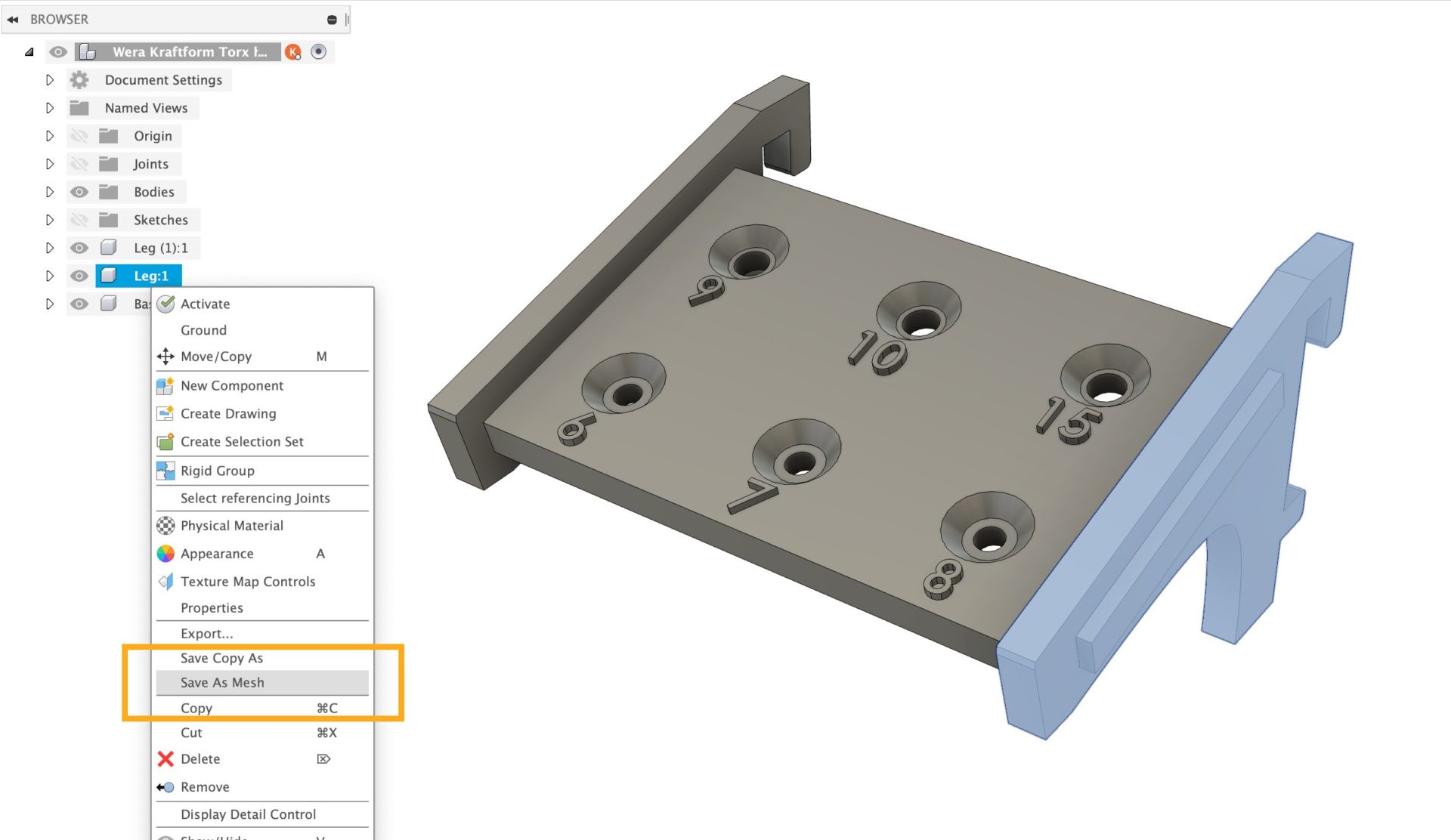
We’re delighted to get this in your hands, and see what you can do with it! We’re always looking for your feedback, so let us know in this Feedback Hub post.
Learn more about Mesh | New video series mesh
New! Reference Objects
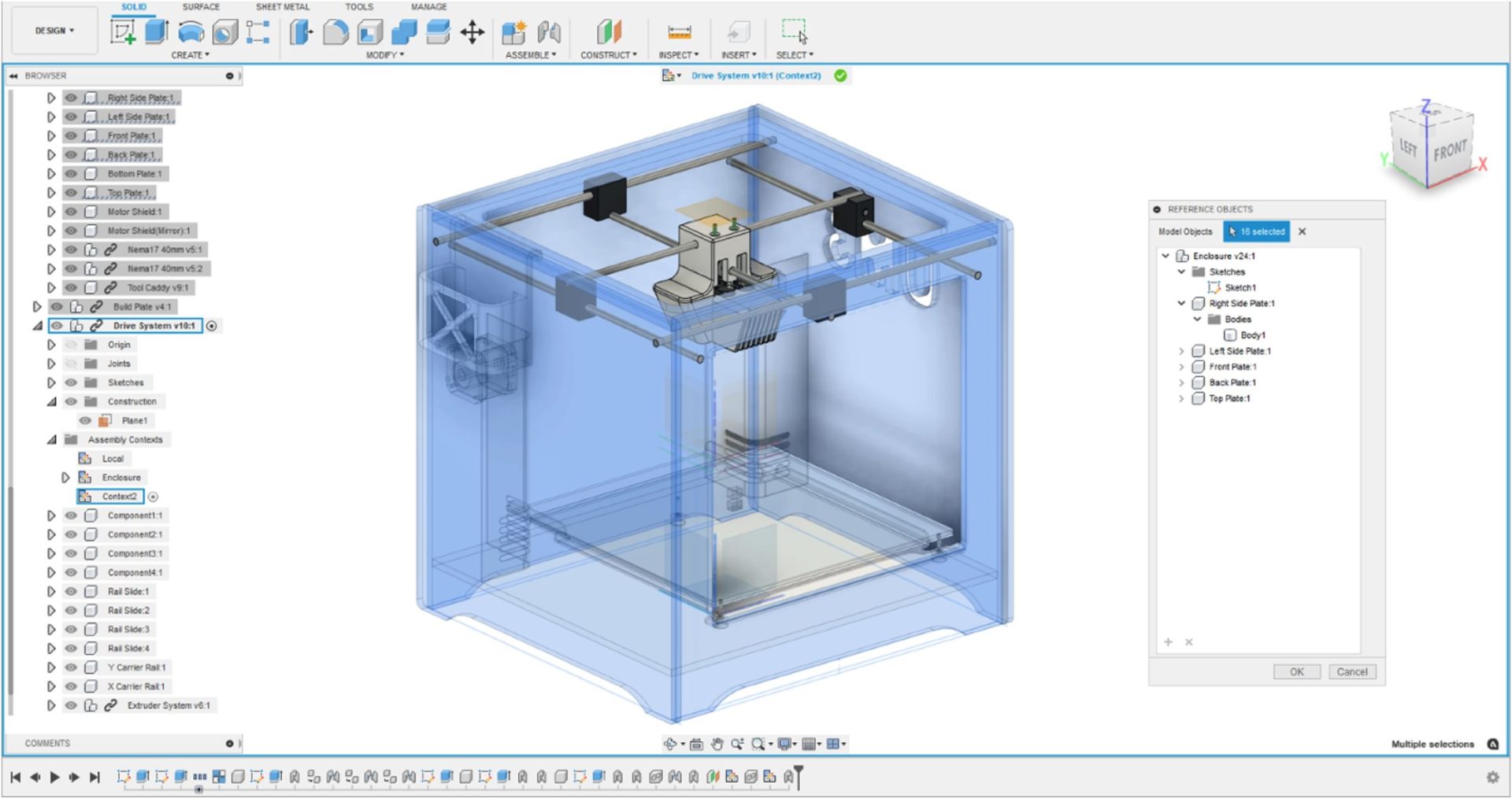

The Reference Objects tool creates explicit associative references between an external component and other design features in an assembly. When you create or edit an external component in place, you can access Reference Objects from the Edit In Place menu at the top of the canvas. You can select design features in the Browser or in the canvas from anywhere in the assembly, and the referenced design features are derived into an Assembly Context.
This lets you explicitly reference objects in an assembly before starting detailed design work. To make detailed design work clearer and easier to perform, reference only the objects in the assembly that are important for a component in context as you work on it.
Learn more about Reference Objects. | Modeling Deep Dive Blog Post
New! Sync All Assembly Contexts tool
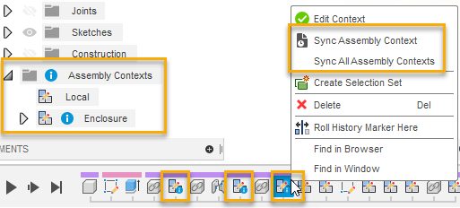
When two or more Assembly Contexts are out-of-sync in an assembly, now you can use the Sync All Assembly Contexts tool to sync them simultaneously, instead of having to sync them each individually.
Right-click any of the out-of-sync Assembly Contexts in the Timeline, then select Sync All Assembly Contexts from the menu.
Learn more about syncing Assembly Contexts. | Modeling Deep Diver Blog Post
Improved! Ruled Surface options
Design Workspace > Surface Tab > Ruled Surface
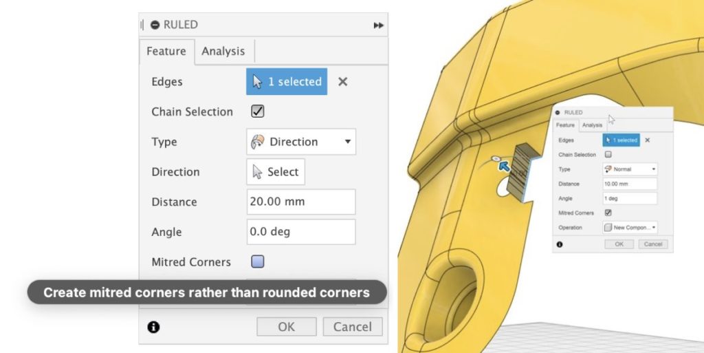
Now when you start the Ruled Surface command, you have the option to choose between creating a body or a component from the very beginning. When you select a planar sketch normal to the sketch plane, the direction of the surface will be automatically determined. The command now also has the option to Mitre corners if you have a draft angle specified.
Learn how to create ruled surfaces.
Improved! Patterning bodies and components just got better
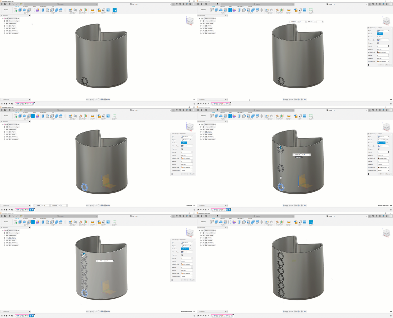
Body pattern preview now shows wireframed instances rather than ghosted bodies
We have been working hard to update and fix issues with our patterning toolset. This release sees improvements made to Pattern Preview and in particular the appearance and performance.
One of the areas of Patterns that bugged a lot of you was around the preview graphics. The old version gave very little detail of what was being patterned as it was just a ghost of the design, now the pattern graphics have been improved to show more of a wireframe instead so you can be sure you have captured all elements of your design before committing to the pattern.

Pattern instance, selection, and cancel speed boost
We have also worked hard to ensure that the patterning toolset is a lot more performant. The first step in this was to make sure Preview was as performant as expected. We have seen a lot of issues with previews taking too long to generate or interact with on large patterns and this can be very frustrating. You should now see Preview performance significantly improved with large patterns taking a fraction of the time to preview. This is the first step towards a re-vamped patterning toolset, stay tuned for more enhancements over the coming year.
New! 3D PCB Options
Design Workspace > Insert 3DPCB > Edit in Place
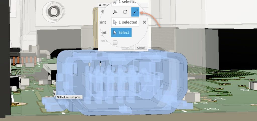
Fusion 360 truly fuses the essence of unification between mechanical and electronic engineers. By providing a single platform for both workspaces, engineers no longer must be converting files to ensure that the PCB layout engineers work with the latest PCB outline supplied by the mechanical engineer. In addition, a significant feature of Fusion 360 is that the mechanical engineer can insert and inspect the PCB in the enclosure. Traditionally, changes to the enclosure that required modifications to the PCB would need lots of communication by both engineers.
[expand title=”keep reading”]
With Fusion 360, the mechanical engineer can use our Edit in Place (EIP) feature and move the electronics parts to comply with the enclosure changes. In this latest update, our developers have now implemented point-to-point moving of parts. Now you can move components referencing other assets on the design. This will make it easier and more precise for you to adapt to changes. In addition, modifications done to the 3DPCB in the design workspace will alert the PCB layout engineer. That way, if necessary, the PCB layout engineer can address updates.
[/expand]
New! IC_Data-Conversion, Wireless-RF, LED parts added to Library
File > New Electronics Design > New Schematic > Add part
In this release, we have added new parts such as digital Potentiometers, A/D Convertor IC’s, RGB LED’s, Bluetooth modules etc. to the respective library categories.

Some of the highlights are WS2812 series, which is one of the popular RGB led’s used in NeopixelRings/Matrix. Now you can make use of these fancy LED parts to your own projects. These led models are assigned with Emissive material, LED lighting effect can be made in the rendering environment.
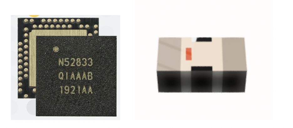
It is rare to find a consumer product that do not include wireless communication. Streaming your favourite tunes have become the normal. In this update, we have added popular Bluetooth SoC from Nordic Semiconductor as well as the filters Optimized for the Chipset.
Nordic’s Bluetooth Low Energy (BLE) Chip is basically a microcontroller with an embedded Bluetooth radio that is intended for Ultra-low power/low-bandwidth applications like IoT.
Improved! Library Editing Performance
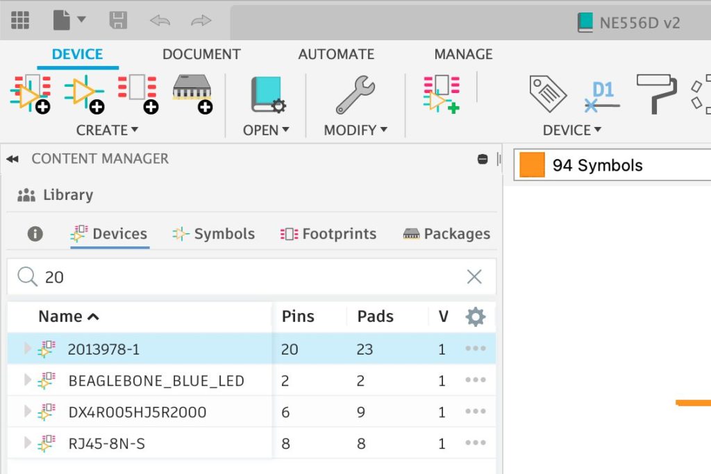
The Fusion 360 library editor is possibly one of the best in its class. It provides you all the necessary tools to build your components with mapped 3D models in moments. In this latest update, you will notice that the performance when navigating the library editor has been vastly improved. For example, switching from Symbol, Package, and footprint listing should be instantaneous. In addition, the search bar has been optimized to get faster results.
Improved! Improved communication between Library and Package editor
File > New Electronics Design > New Electronics Library

Our team of developers has optimized the communication between the library editor and the package editor. As a result, you will notice an in-progress animation while your new package is added to your library. Remember that the Fusion 360 package editor is the workspace used to conveniently create or map existing 3D models to your footprints.
Improved! 3D PCB now considers DRC via limit when creating solder mask
File > New Electronics Design > PCB Layout > 3DPCB
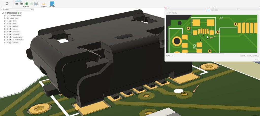
After laying out a circuit board, the PCB layout engineer needs to route the signals. This means you will be defining a copper path on the PCB layout for the connections defined in the schematic. Fusion 360 provides a host of options that can assist or automate this process. The PCB can consist of 2 layers or more. Currently, Fusion 360 can handle up to 16 routing layers with support for Blind and Buries vias. During the process of routing a signal, it is often you will want to switch layers. At this point of transition, Fusion 360 will place a via. A via is a drill hole on the PCB plated through and will transfer your signal between multiple layers.
[expand title=”Keep reading”]
A solder mask fully covers your PCB during the manufacturing process to protect your PCB from corrosion and short circuits. It is required to have openings on the solder mask for each pad. That way, you can solder the electronic components. The solder mask opening on each pad will work as a shield, ensuring that the solder will not bridge adjacent pads and vias that may cause short on the PCB. The engineer has the option to have vias covered by the solder mask or exposed. A covered via is usually referenced as a tented via. There are many pros and cons to having vias tented or exposed. In this latest Fusion 360 update, when switching to 3DPCB with solder geometry enabled, you will be able to distinguish exposed and tented vias as you already have in the manufacturing previewer. By having this feature implemented, you can verify your intended vias status and be on the lookout for unwanted bridges.
[/expand]
New! Export Properties Data from Explore
Generative Design > Explore > Export > Export CSV
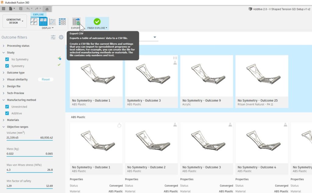
One of the primary goals of Generative Design is to help you accelerate the process of finding the best design outcome to solve your design challenge. You have told us that sometimes this requires additional data analysis and processing outside of the Explore environment. To support your current design evaluation workflows, we are now allowing you to export all the data and properties associated with outcomes to a CSV file. The Export command is aware of your current Outcome Filter states and Visibility Settings, so what you see in Explore is what you will get in the exported CSV file.

Improved! Symmetry Now Available for Additive Manufacturing Constraint
Generative Design > Define > Design Space > Symmetry

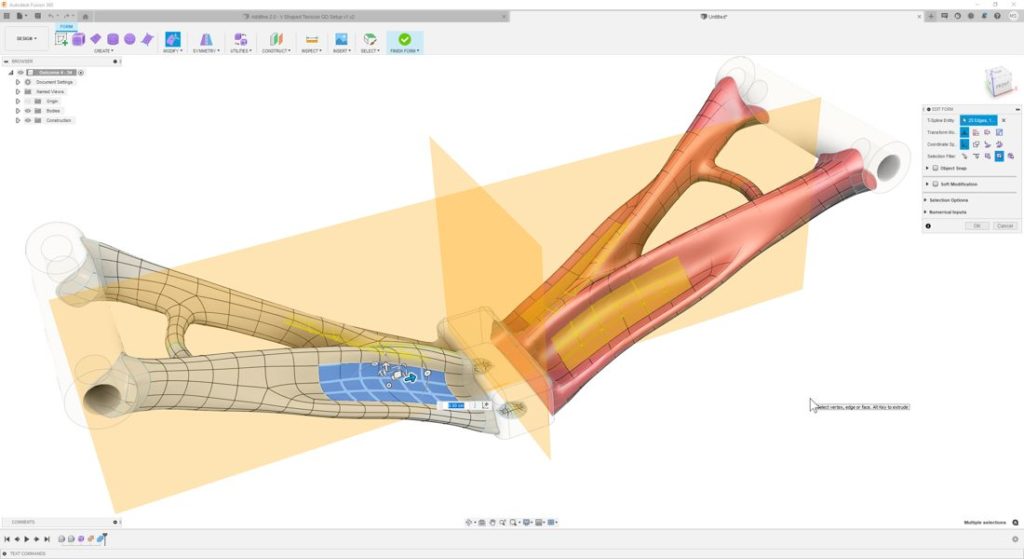
Symmetry constraints have been part of the Experimental Generative Solvers and Features preview for a while now but were limited to Unrestricted outcomes. In this update, we have enabled Symmetry for Additive Manufacturing outcomes. Just like Unrestricted outcomes, the resulting design will have an editable T-spline in the timeline with symmetric behavior enabled, so any edits will behave symmetrically, as well. Note: You must have the Experimental Generative Solvers and Features preview turned on to use Symmetry constraints.
Learn more about Symmetry Plane
Improved! In-canvas continue button now available with Symbol tools
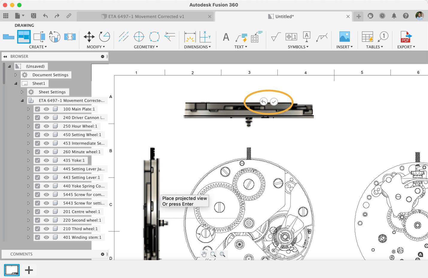

Similar how you placed your projected views with a Checkmark button to confirm your placement, we’ve now extended that checkmark experience to other drawings tools such as Surface Texture, Feature control frame, Datum ID, Welding Symbols, as well as Taper and Slope symbols. This allows you to quickly confirmwhere you want to place your symbols in context to the placement itself, while reducing overall mouse travel.
New! PowerMill pan/zoom/rotation keyboard/mouse shortcuts
Preferences > General > Pan, Zoom, Orbit Shortcuts
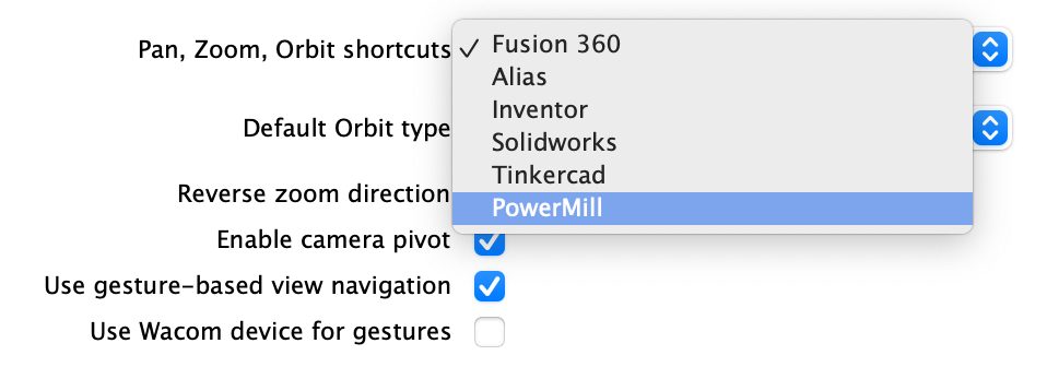
A significant segment of our Fusion 360 community consists of machinists and CNC machine programmers. If you use PowerMill and have been trying to take advantage of what Fusion 360 has to offer, we’re happy to let you know that you can now set the Pan, Zoom and Orbit preference to adopt the same behavior as PowerMill.
The view rotation uses the same algorithm as PowerMill and the other ex-Delcam software packages, and the view rotation anchor is set to the center of the display. This makes it much easier for those of you coming from PowerMill to manipulate the view in Fusion 360.
New! 2D pocket Recognition option for Contour Mode
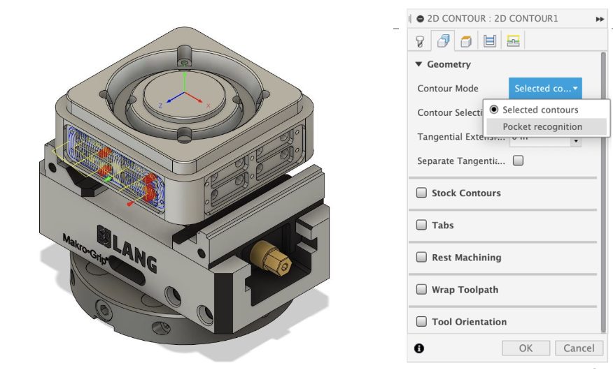
Now as a contour mode option for 2D Contour, 2D Adaptive and 2D Pocket operations, “Pocket recognition” contour mode provides you the ability to automatically recognize boundaries. You can also filter by Corner Radius Min/Max, Depth Min/Max, as well as Include/Exclude Holes.
Learn more about 2D Pocket Recognition
New! Alfawise printers added to the machine library
Manufacture > Additive Tab > Machine Library
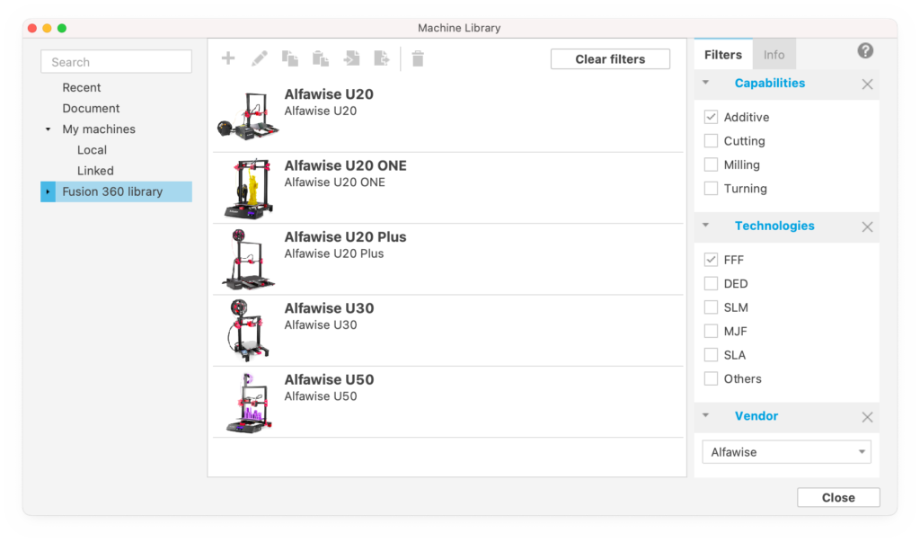
In this update, we’ve added support for Alfawise printers as part of our Machine Library with additive capabilities. These include Alfawise U20, U20 ONE, U20 Plus, U30, and U50 3D printers.
New! Multi-Edit in Component Sources (Nesting & Fabrication Extension)
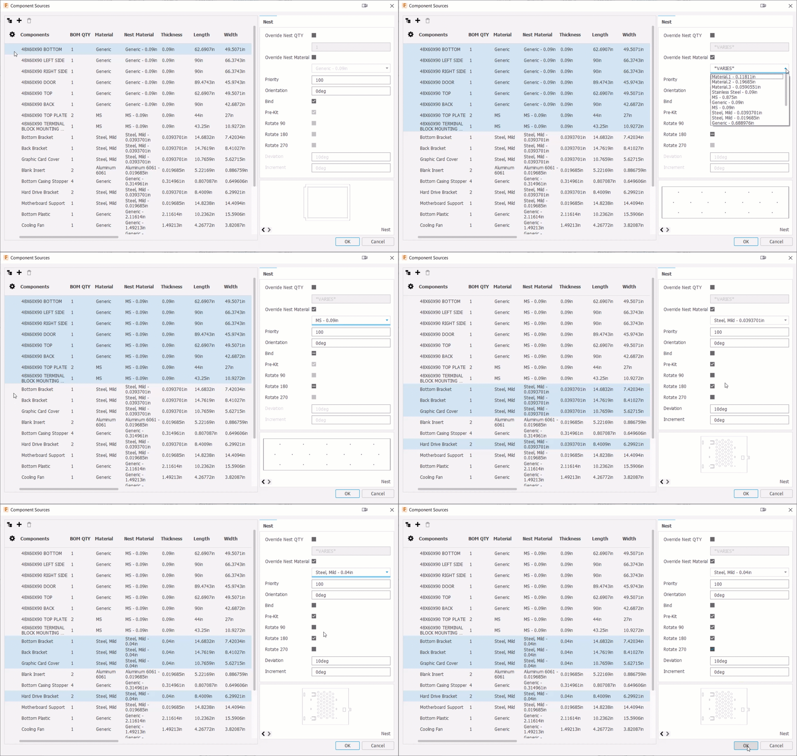
The Component Sources dialog in Nesting & Fabrication Extension now supports a multi-edit experience which lets you CTRL+Select OR SHIFT+Select multiple Components and edit their Nest Parameters at once.
New in Preview! Orientation by edge selection (Advanced Arrange Preview)
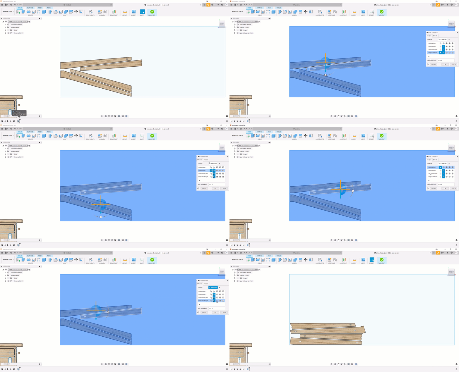
The Advanced Arrange Extension Preview has a new option that allows you to select an edge that you want aligned parallel to the length of your stock (X axis). Preview shows the arrangement results. As needed, select a different edge on the component and see how the Preview updates the part orientation.
New in Preview! Optimized Perpendicular Pass in Steep and Shallow (Machining Extension)

The Steep and Shallow strategy has a new option to output optimized perpendicular passes when using Parallel only (Set Threshold angle to 90 and shallow).

This option analyzes the gradient of the underlying surface, then if the surface is too steep to maintain a good step-over, it’ll automatically flip the pass direction by 90 degrees to machine these steep areas. The result should be a more efficient toolpath that machines a more consistent surface finish.
Learn more about Steep and Shallow optimized perpendicular passes
Improved! Continue Rest Machining from Preceding Setup
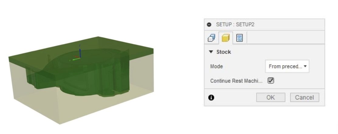
You now have the option to turn on Continue Rest Machining with the Mode set to “From preceding Setup”. This enables Fusion 360 to automatically capture the stock from preceding setups. This behavior will only work if both “From preceding setup” and “Continue Rest Machining” are selected.
Learn more about Continue Rest Machining from Preceding Setup
Improved! Turning Depth of Cut
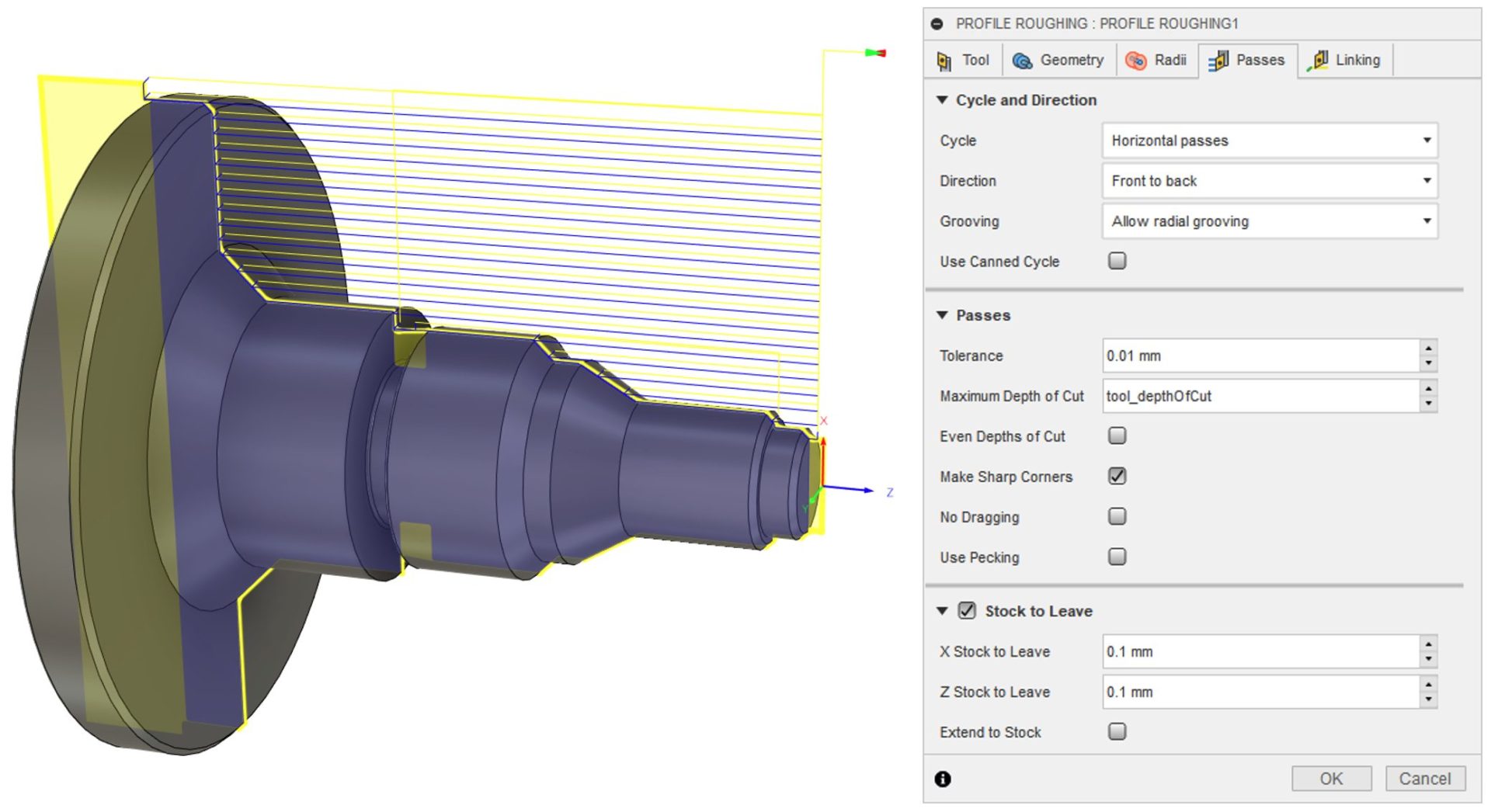
Stemming from the conversations happening in this forum thread, we’ve added a new Depth of Cut option to general Turning Tools as well as Boring Tools. This will now help you automatically set the maximum depth of cut parameter for Profile Roughing toolpath. It also creates a parameter link between the document tool library and operations

If tool depth of cut is updated, all toolpaths that use that tool will also be updated. You can also override the Toolpath depth of cut anytime.
Improved! Timeline graphical preview for toolpath modifications
Manufacture > Milling > Modify > Trim
Each item on the timeline can now be selected. This enables you to see the result of a specific toolpath modification. The preview shows how the edit was performed, the result of the edit, and if applicable, the region of the toolpath which was removed.
New! Browser Command Input
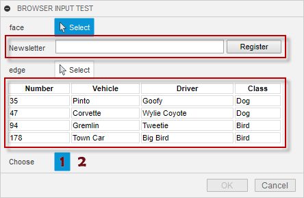
The Browser Command Input is a new type of command input that defines an area on a command dialog like all other command inputs. The difference is that what is displayed in that area is a rendered HTML file. The ability to use HTML to define the contents of your command dialog completely opens up what you can display in a command dialog because you’re no longer limited to the set of standard command inputs currently available. Whatever you can design using HTML, you can now display in a command dialog.
[expand title=”Keep reading”]
The ability to use HTML is similar to what you can do with palettes, but with a command input, you get command behavior, and it mixes with the other command inputs. Below is an example of it in use.
The command is written the same as any other command. When the user clicks the button to run the command, the command-created event is fired, and the add-in adds the command inputs it needs to collect the input the command requires. In this example, the command has created a selection input, a browser input, a second selection input, a second browser input, and finally, a button row input. The first Browser Command Input looks very similar to a text command input, except there is a button beside the text field. The text “Newsletter” is the name assigned when the command input was added to the dialog. The referenced HTML defines the text field and the button. The second HTML command input is set to be the entire width of the command dialog, so in this case, the name is not used. The HTML it is referencing contains the table information you see displayed in the dialog.
There are also events supported that allow your add-in to send messages to the JavaScript code associated with the HTML and for the HTML to be able to send messages to your add-in. With this, you can react to changes the user makes in the HTML and perform the desired action in Fusion. You can also pass information from Fusion to the HTML that it can use in whatever way it needs.
[/expand]
You can read more about this command input in the User Manual topic on command inputs.
New! Log method on the Application object
We know it is better to write debug information to the TEXT COMMANDS window instead of popping up message boxes. It’s been possible for a long time to write to the TEXT COMMANDS window but it’s not obvious and takes a few lines of code. The API now supports a log method on the Application object. You can log to either the console, which is the TEXT COMMANDS window or the Fusion 360 log file. In its simplest form you can use the following to write a message to the TEXT COMMANDS window.
app.log(“This is my message”)
Improved! Custom Feature capabilities
See the Custom Feature topic in the API User Manual contains more detailed information about these enhancements.
Here are fresh videos by you that have just dropped on YouTube!
Here are some YouTube highlights for June 2021:
To see details around this, our extended list of fixes, as well as known issues, check out this forum thread in our support forum.
See Known Issues and Fixes for July 2021

By clicking subscribe, I agree to receive the Fusion newsletter and acknowledge the Autodesk Privacy Statement.
Success!
May we collect and use your data?
Learn more about the Third Party Services we use and our Privacy Statement.May we collect and use your data to tailor your experience?
Explore the benefits of a customized experience by managing your privacy settings for this site or visit our Privacy Statement to learn more about your options.