Elevate your design and manufacturing processes with Autodesk Fusion
We created the Machining Fundamentals series to help you brush up on your CAM knowledge, whether you work in a machine shop or are just getting started. In-house machinists at our Birmingham Technology Center host each episode and provide a detailed overview of a tool/process. In the last edition, we covered toolpaths. Here we have an introduction to the Work Coordinate System (WCS)—what it is, why we need it, and how to set it up in Fusion.
What is the Work Coordinate System?
The Work Coordinate System is a reference point set in our CAM workspace and on our machine. All machine coordinates are drawn from the WCS. It is needed for a wide range of manufacturing equipment, including milling machines, lathes, and laser cutters.
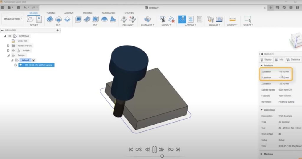
Let’s look at a quick example in the video. All CNC machines run off NC codes, which include coordinates. The WCS—which is X, Y, and Z—is in the middle of the component. These coordinates drive the toolpath, and are referenced from the WCS.

On a 100 x 100 x 20 mm aluminum block, our tool will be at the coordinate point of 50 mm, plus the radius of the tool when traveling down this face. The tool is on the opposite axis when traveling down the side perpendicular to it. The tool’s diameter is 16 mm, so we expect the coordinates to be 50 mm plus 8 mm, or 58 mm in total.
Translating the Work Coordinate System to the Machine
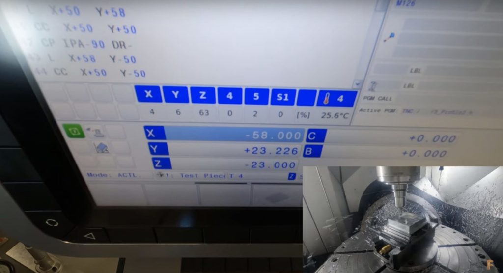
How does this translate to the machine? In the video, the WCS is set on a vertical mill. You may know this as G54, a work offset, or a datum, among other things.

It’s important that the WCS’s position in Fusion 360 matches the offset that is set on the machine. Let’s refer to the coordinates of the previous toolpath. When going down the sides of our part, the coordinates are 58 mm on the x- and y-axes, with our block being just over 100 mm on the x- and y-axes. By setting the coordinate system in the middle of our part on the machine, our tool can machine all sides of the part.
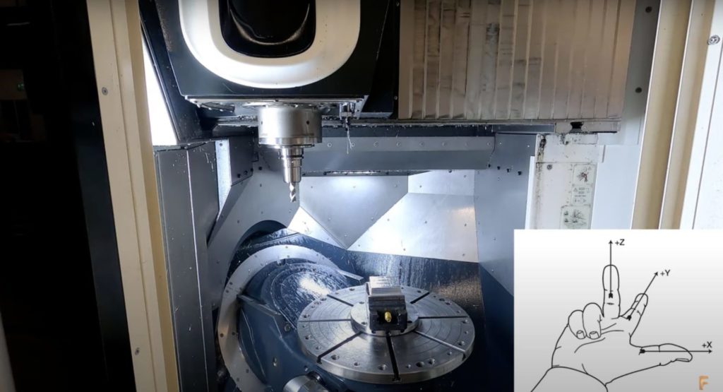
The Right-hand Rule

The right-hand rule can help you figure out the axis direction on the machine. The video at the top of this article shows how to use the right-hand rule to pinpoint the direction of each axis while looking straight at the machine.
Ensuring the Correct Position and Orientation of the WCS
It’s important to know the direction of each axis because it guarantees the Work Coordinate System is correctly positioned and orientated. We can check this by ensuring that a known part feature aligns with our x- or y-axis.
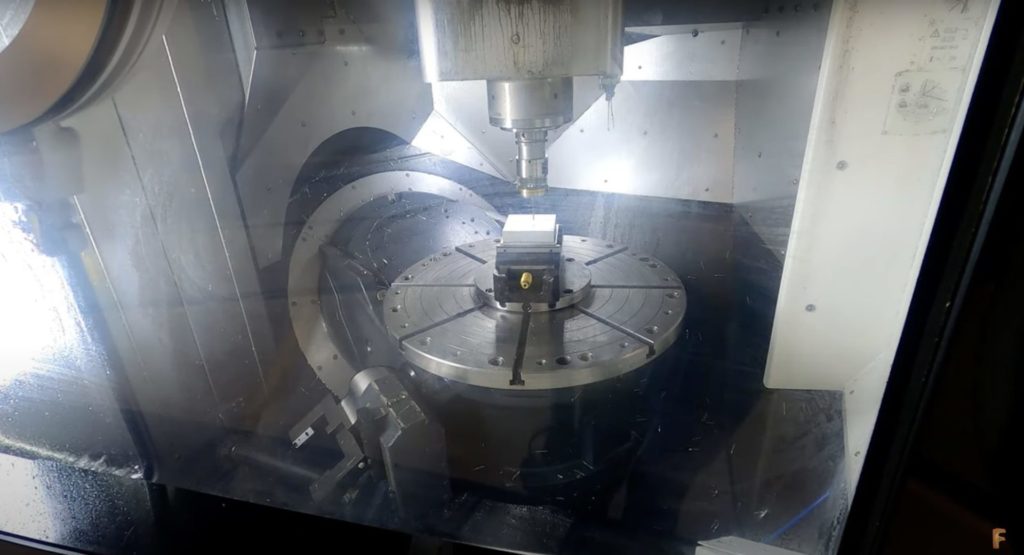
The video above shows an example with a vise. The jaws are machined perfectly flat and parallel to each other for optimum accuracy. We must ensure that the vise jaw is running parallel with our axis, or the x-axis in this case. Doing so guarantees that our machine setup replicates what appears in Fusion 360.
Now that we’re certain of the Work Coordinate System’s orientation, we can look at the position. There are numerous ways to set our WCS, and different reasons for placing it where we do.

Using the probe, I will set my Work Coordinate System on the middle of the top of the part. The probe is the quickest and most convenient way to uphold accuracy to microns. I’m placing the WCS on the middle of the top of the part because all of its faces are already machined. We should always reference our machine geometry when we can because it gives us the best chance of getting our WCS exactly where we want it.
More Machining Fundamentals Coming Soon
Stay tuned: following this episode about milling tools, we’ll be publishing Machining Fundamentals episodes weekly. Future topics include NC code, work coordinate systems, and more. Check out the rest fo the Machining Fundamentals videos below:
Machining Fundamentals: Introduction to Milling Machines
Machining Fundamentals: Introduction to Milling Tools
Machining Fundamentals: Introduction to Lathes
Machining Fundamentals: Introduction to Post Processors
Machining Fundamentals: Introduction to Toolpaths
In the meantime, download Fusion to start machining smarter today. Learn more about how to maximize your machine with Fusion here.