& Construction

Integrated BIM tools, including Revit, AutoCAD, and Civil 3D
& Manufacturing

Professional CAD/CAM tools built on Inventor and AutoCAD
32 min read
V.2.0.13619 (Current)
This minor update fixes a few outstanding issues:
V.2.0.13615 – The Big Quality of Life Update
This product update is all about “quality of life” (referred to as QoL). More specifically, your quality of life when using Fusion 360 day-to-day. We doubled down on improving the tools that exist today, and fixing those annoying issues that have been bugging many of us. And in the spirit of giving you the full scoop, we are not going to spare any details. We’ve included everything in this blog post. All the new stuff, all the improvements, and all of the fixes in its entirety. Yup, this is a meaty one, so let’s get down to business.
Protip: If there is a section that interest you the most, use the table of contents below to jump to it. Our Autodesk experts will also be hosting a free virtual live event demoing what’s new very soon, so if you want to see these improvements in action, register at the bottom of the page.
Performance boost
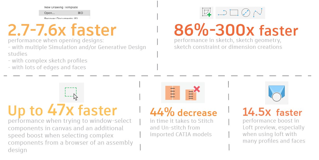
Opening, saving, and closing documents will be noticeably faster, especially when there are multiple Simulation and/or Generative Design studies and load cases present in the document. Users could see up to 5.6x speed improvements in case of large files.
Opening design documents with complex sketch profiles now happens 5.6x faster than previous versions. Also, there is a general improvement for designs with lots of edges and faces. It shows 7.6x improvement on internal testing dataset.
Sketch: Several changes have been made to the Sketch area, so you can feel a significant (300x faster!) performance improvement in sketch, sketch geometry, sketch constraint or dimension creations.
Selections: Fusion 360 now responds much faster when you try to window-select components in canvas. Up to 47x faster. You could also notice a boost in speed when you try to select complex components from the browser of your assembly design.
Stitch/UnStitch: With this product update focusing on maturing what’s already there, we’ve made some noticeable performance gains in various modeling commands and modeling workflows: The time it takes to Stitch and Un-stitch surfaces generated from imported CATIA models has dramatically decreased by 44%, from 34 seconds down to 19 seconds.
Loft: You should also be able to feel a boost in Loft preview performance (14.5x faster than before), especially when you’re using Loft with many profiles and faces.
Display Component & Display Mesh Face Groups

Under the Inspect drop-down menu, we updated how we call a couple of the commands in the list:
Component Color Cycling Toggle is now called Display Component Colors Mesh Face Groups is now called Display Mesh Face Groups
Now it reads more concise and consistent with what you’re trying to do, starting with the action.
Cancel stalled uploads in Job Status Dialog
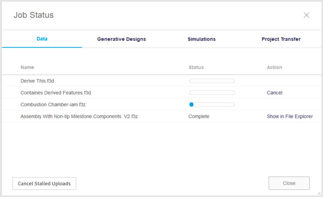
Internet issues happen, and sometimes at the most inopportune times. Have you ever experienced an upload that may have gotten stuck, or never completed? The original troubleshooting method to fix this was to use text commands to delete and backup the upload queue, or even deleting XML files. We’re happy to report that this is no longer the case! Now there will be an option built into the UI that detects if the upload/save has timed out, and will allow you to cancel the ‘stuck’ uploads. Once canceled, the files can then be uploaded or saved again.
Fixed: Crash on launch on MacOS with many Crash Error Reports
For customers that had multiple Autodesk products installed alongside Fusion 360 on MacOS, you likely experienced dozens of crash error reports when launching Fusion 360. We know this was a major annoyance for many – and we are happy to say it is officially fixed with this update!
“Read-Only For Me” now available from Fusion Team
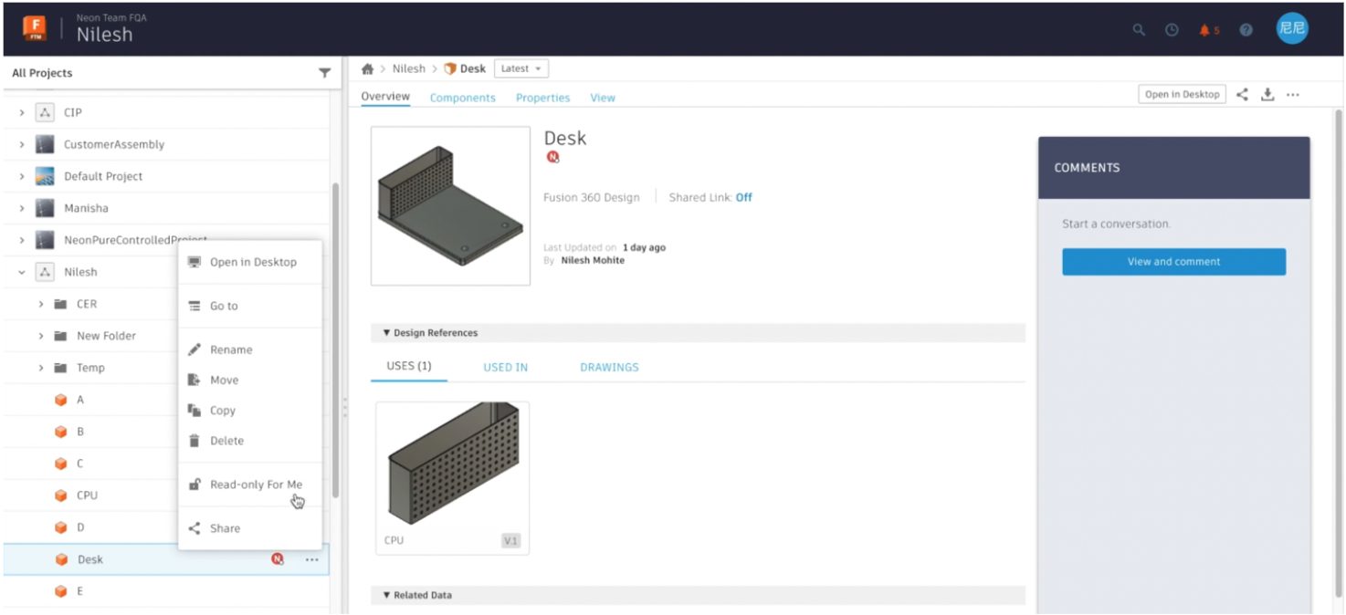
Back in January, we introduced Read-Only For Me, which lets you temporarily make designs read-only for yourself, so you’re free to view, analyze, or experiment with a design while other project members continue editing. With this update, you can now use Read-Only For Me from Fusion Team.
Whether you’re away from your desk or out of the office, if a design is still reserved by you and you’re blocking other project members, it’s now easier to unblock access from anywhere. You can open Fusion Team in any web browser and use Read-Only For Me to remove your reservation so that another project member can edit it.
Once you’re back at your computer where Fusion 360 has the design open, you’ll see it’s read-only for you. You can either click Make Savable at the top of the canvas or close the design to make it savable for you again.
Learn more about Read-Only For Me
Link to additional blog post
Create a lofted flange in Sheet Metal Flange tool
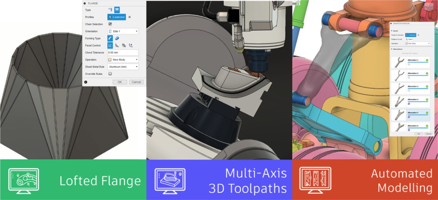
So many have you have asked for this and we’re happy to say that it’s finally here. Now when you’re creating Sheet Metal parts with the Flange tool, you can also create a lofted flange by selecting the Lofted Type within the Flange command dialog. You can also pick the orientation, Brake Form vs. Die Form, Facet Control options such as Chord Tolerance, Facet Angle, Facet Distance, Face Number, as well as specify the Sheet Metal Rule that applies to your part. Having the ability to create lofted flange should enable you to explore more complex sheet metal possibilities, and easily turn them into a flat pattern.
Learn how to create lofted sheet metal flanges
Expanded modeling tools now available directly in Assembly Contexts
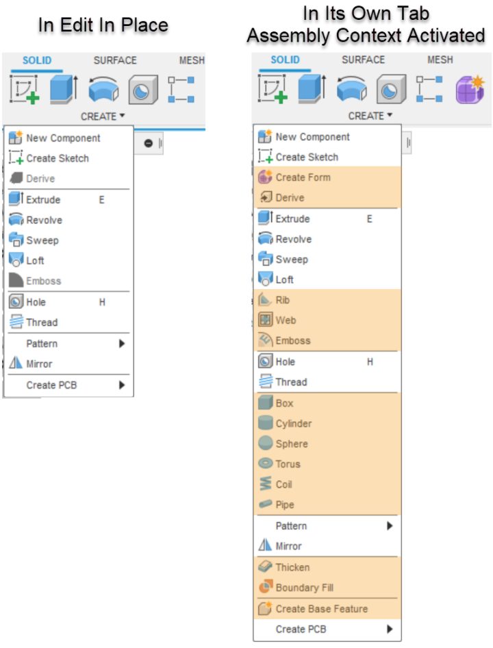
If you’re using Edit In Place for contextual assembly editing in distributed designs, this one’s for you. When we first introduced Edit In Place, we only included an initial subset of the most commonly used modeling tools available in the Design workspace. This was also true when you opened an External Component in its own tab and activated an Assembly Context. Many of you have requested access to some of the tools that aren’t available there.
With this update, when you open an External Component in its own tab and activate an Assembly Context, you can now use an expanded set of modeling tools while still working with objects you’ve referenced in the context of an assembly. The expanded list of tools includes all the primitives, Surface > Create > Loft, the Surface > Modify tools, all the tools on the Mesh tab, the Form tools, and many others. (Note that a short list of tools that control joints and motion will still switch you back from the Assembly Context to the Local context.)
As you continue exploring distributed design workflows, let us know which tools are most important for you as we plan for future updates.
Learn how to edit existing assembly contexts
Rest Tool helps you create flat areas on curved plastic parts
Rest Tool is available as part of the Product Design Extension
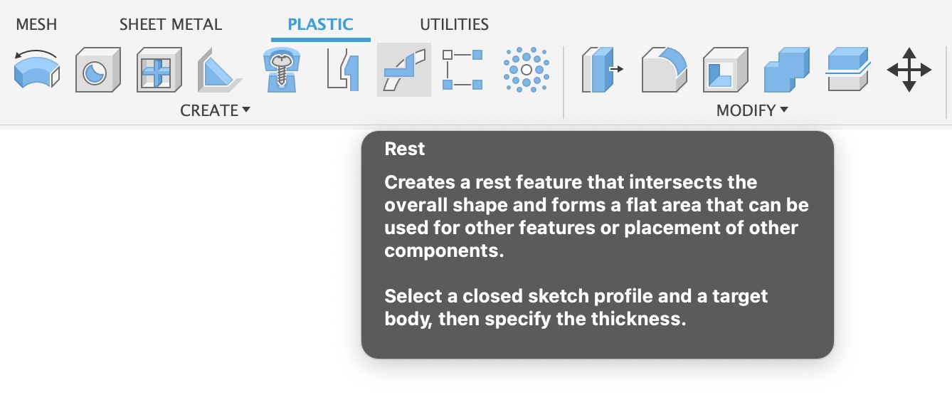
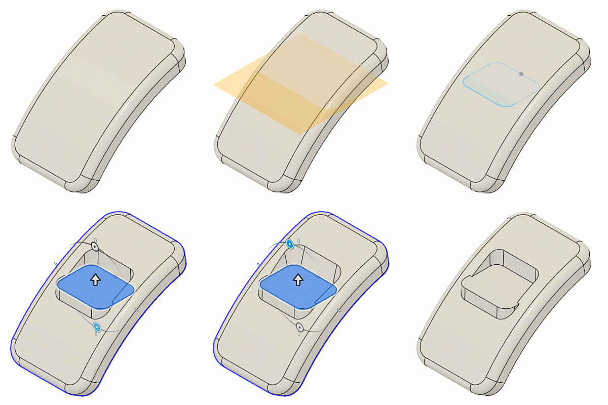
Many times when you’re designing a product, you may want to create a flat areas on a curve surface so that other parts can easily mount to it. That’s where this new Rest command comes in. Now you can grab a sketch profile and use it to create a flat face, in relation to the curved surface of your existing body. The command will then do its magic to cut away or add material depending on the thickness you require.
Snap Fit improvements: selection modes and rotation options
Snap Fit is available as part of the Product Design Extension
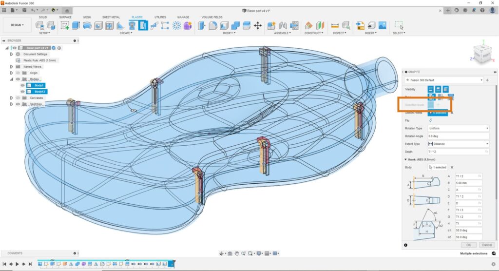
Two new selection Mode options – Automatic and Manual. The Automatic options is on by default, and it automatically selects all visible sketch points to place multiple snap fits at the same time. You can clear the selection set and switch to the Manual selection mode if you want to select your sketch points manually in a complex design. This will help you select points to place your snap fits faster.
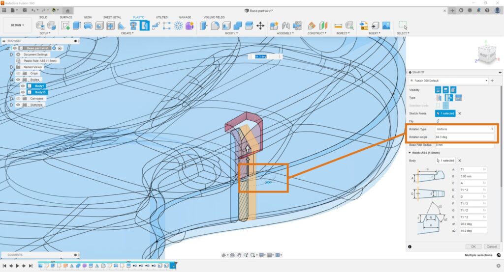
New Rotation Options -We’re also adding one of the most common requests to Snap Fit: the ability the control the rotation of each snap fit independently. You can adjust the Rotation Type to one of 3 new options:
Select modeled geometry as unit cell geometry for Volumetric Lattice
Volumetric Lattice is available as part of the Product Design Extension
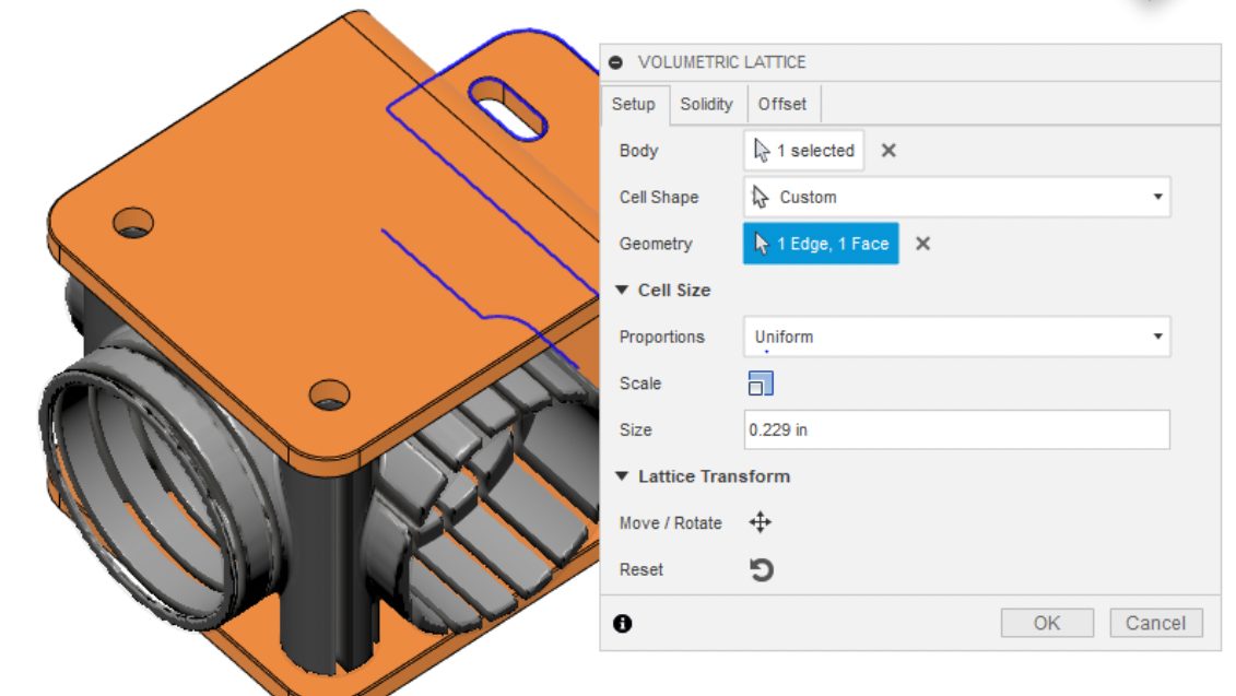
If you’ve been using the Volumetric Lattice tool as part of your Product Design Extension, you’ll be happy to hear that we’ve improved the tool by giving you the ability to select modeled geometry (sketch lines, for example) as unit cell geometry.
Automated Modeling Public Preview now available
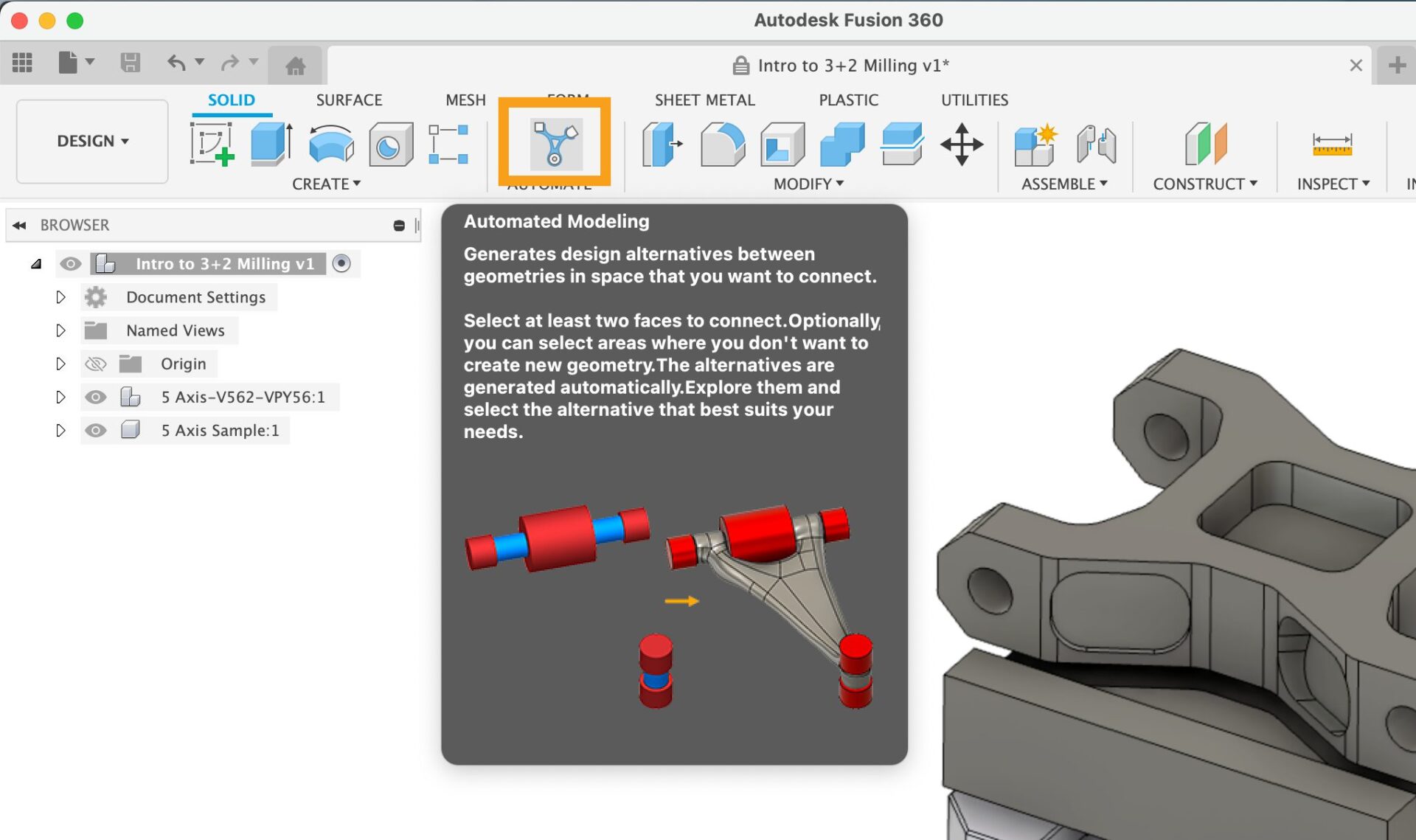
In this release of Fusion 360, we are expanding the reach of our Generative Design technology into everyday modeling workflows and releasing a new tool, Automated Modeling, found in the Design workspace, on a new tab called Automate.

Automated Modeling will allow you to rapidly create and consider multiple design alternatives for connecting two or more faces in your design. Additionally, you can prescribe additional design intent by defining bodies for Automated Modeling to avoid during shape creation. The results of Automated Modeling will consist of a new Automated Modeling feature in the timeline followed by editable T-spline geometry to allow you to further refine and influence the direction of your design.

The Automated Modeling preview is all about increasing your creativity and productivity during your design workflows and we would love to hear how you think we can make it better. Please share your feedback and experience with the Automated Modeling preview in the forum link below – we can’t wait to hear from you.
Share Feedback
Learn more about Automated Modeling
In this QoL update for Electronics, we focused most of our time on addressing the ideas and feedback that you have taken the time to provide us. We are pleased to deliver this update that is packed full of enhancements to your design experience, product stability, and overall performance of Fusion 360 Electronics.
Expanded keyboard shortcuts

We have expanded the keyboard shortcut functionality within the Electronics workspace to enable you to specify commands or a combination of commands. With this new functionality, you can assign shortcuts to execute a User Language Program ( ULP) or your preferred scripts. An excellent example of using this new feature is adding multiple grid options for laying out the PCB; this makes it easier to place components that require a different placement grid.
Learn more about Electronics Keyboard Shortcuts
Productivity enhancements

We understand that productivity is the name of the game, and you cannot waste time searching around for the correct command or struggling to define parameters for the active command. We have spent some time streamlining commands to make everything a bit more intuitive and faster. For example, remembering the exact name of NETs, Pins and Parts on your schematic can be frustrating – even requiring guesswork on more complex designs across multiple sheets. Now, if the appropriate command is active, recently used names in your design will now appear – eliminating guesswork through autocomplete. Check out the productivity improvements we have made in this update:
Learn more about setting Electronics preferences
Learn more about creating Assembly Variants
Learn more about preparing manufacturing data
Performance improvements & fixes

Most circuit board designs require polygon copper pours as they help propagate a specific signal on your PCB around the entire board or specific area. You have shown us that on more complex designs you could expect to create over 50 polygons on multiple layers! When editing the design, the substantial number of polygons can translate to poor performance. For this update, you will notice that we have vastly improved the performance of Fusion 360 electronics with better handling of polygons. Here are a few more examples of performance improvement we have worked on:
Stability fixes
In the event that you encounter a crash whilst using Fusion 360 Electronics, there is the option to provide a report which helps us understand in more detail how and why the crash occurred. Thanks to those reports (we read them all!), we’ve spent the last few development cycles fixing the following issues (the list is rather long, so if you want to really dig into it, click on Show Fixes):
[expand title=”Show Fixes”]
[/expand]
EAGLE migration
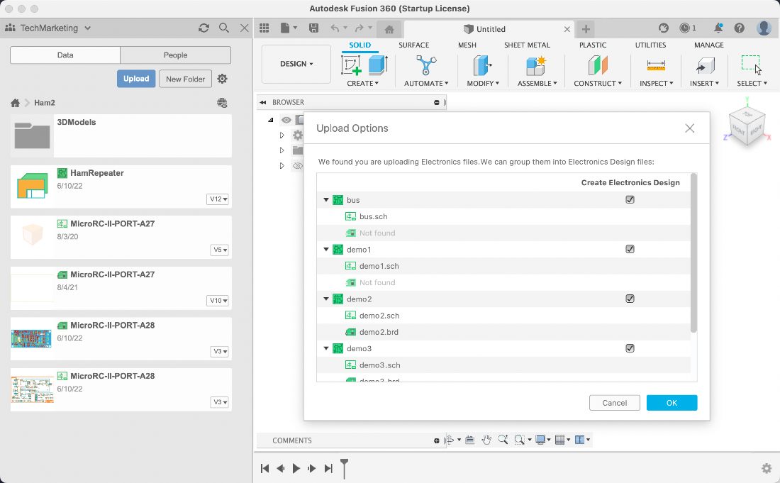
We know that many of you were unsure how to productively migrate to Fusion 360. In this update, we have made a few updates to ensure the transition from EAGLE to Fusion 360 is much easier for you. EAGLE Design Files and Library files are 100% compatible with Fusion 360 electronics. The first time you launch Fusion 360, it will automatically detect if you have local EAGLE libraries and give you the option to upload them. In addition, when uploading your EAGLE design files, you now have the option to create Electronic Design documents. The electronic design document keeps the schematic and circuit board synchronized.
Generative Model filter now in Explore Environment

When working with Generative Design, it is common to consider variants to your design space definition using Generative Models. While providing a path to a larger exploration and more potential design solutions it did make exploring the results a bit more tedious and forced users to name their studies in a unique way to capture this intent. To improve this workflow, we have added the ability to filter against the Generative Model in the Explore environment.
Improved terminology in Fluid Path study type

Since our Fluid Path study type has been in preview, we have received feedback from you that the concepts of preserves, obstacles and a starting shape were much more unclear when working in a fluid domain versus a structural domain. To help add clarity, we have renamed these commands to be more precise in what they represent, where some represent the fluid being created and some represent the surrounding solids that contain or obstruct the flow.
Learn more about Fluid Path study
Attribute fonts & blocks dragging
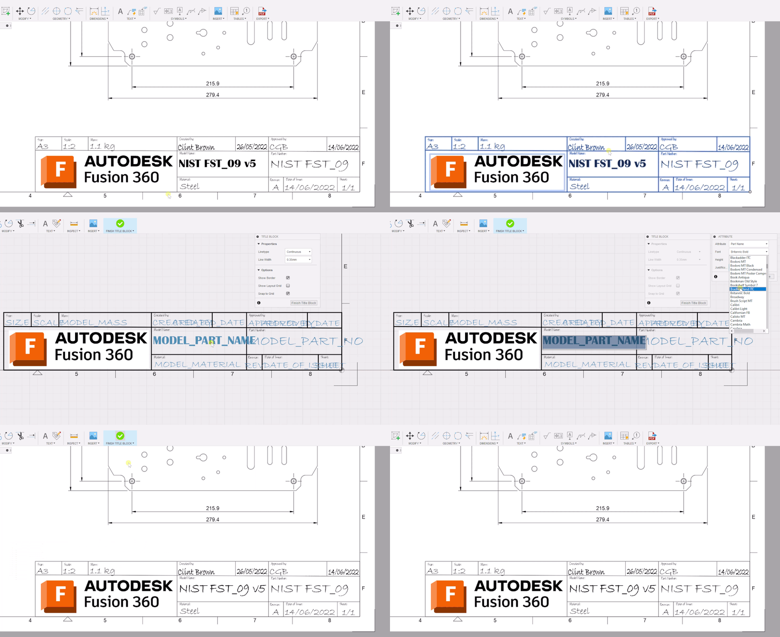
Now when you’re working on your drawings title block you can change the font type going into the Edit Title Block mode, double-clicking on the attribute you want to edit, and then selecting the desired font.
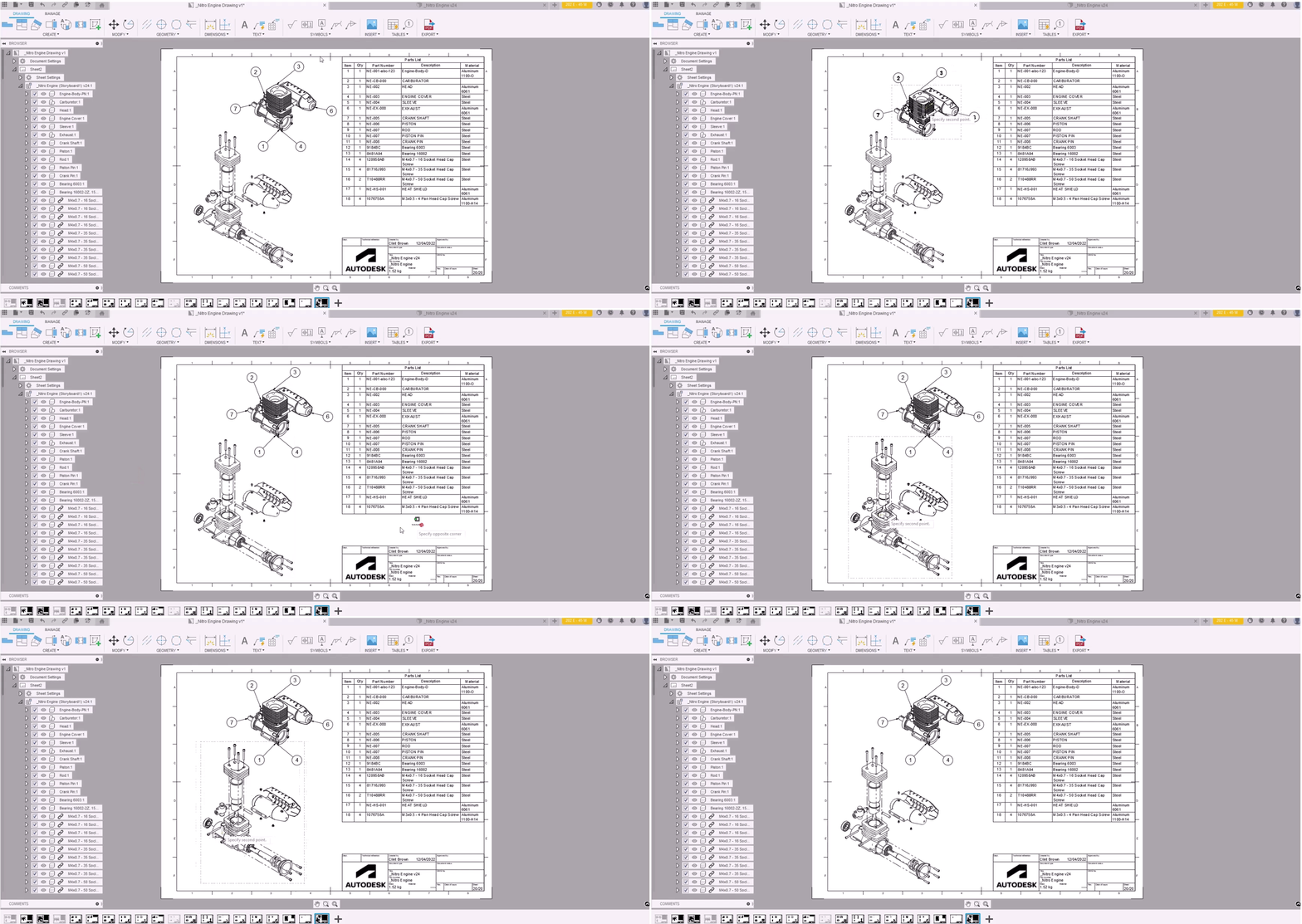
We’ve also improved the dragging behavior where any selection will no longer cause the title block or border to move. Title blocks and borders can now only be moved via the Move command.
Export Flat DXF
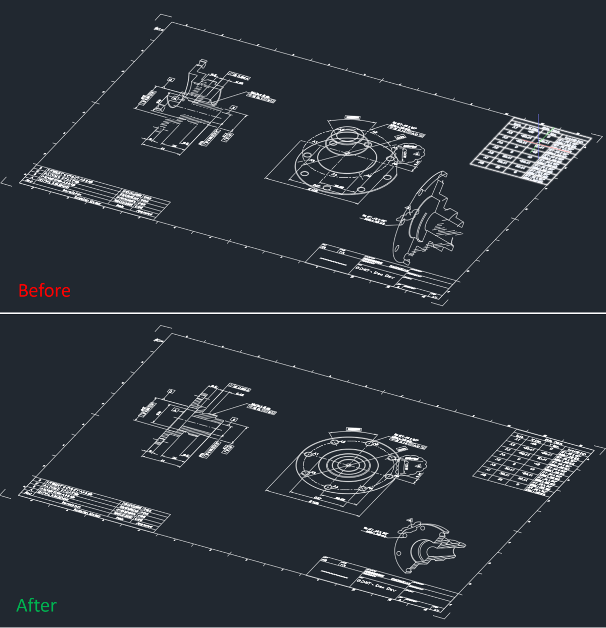
Before when you exported a DXF from the Drawings environment, the export files contained some Z-axis geometry, which made it difficult to work. Now when you export a drawing as DXF, we made sure that the DXF is completely flattened.
For the Manufacture Workspace, this update contains more than 150 Quality of Life (QoL) improvements that positively affect all areas, including milling, tool libraries, turning, nesting, metrology, additive, cam simulations, and post processing. In the spirit of this update, we’re not going to bury these improvements in some forum thread. Instead, we’re going to include the work in all of its glory in this blog post. Let’s start with what we focused on in Milling.
“Show Toolpath Data” dialog updates
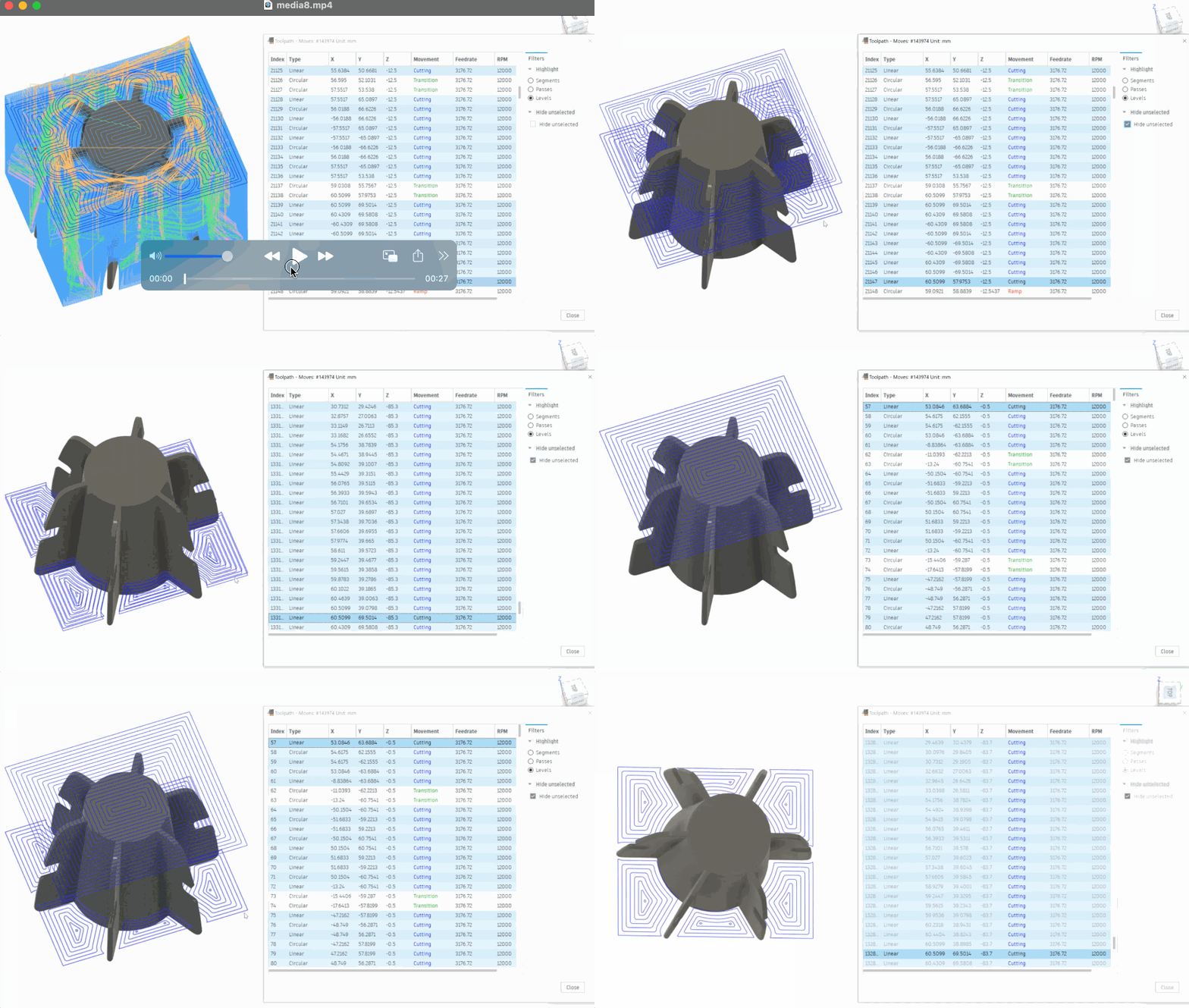
We added new filters to allow any combination of tool-path segments, passes, and/or levels to be displayed or hidden to aid toolpath visualization. Note that “level” is only available for 2D Adaptive, 2D Pocket, Face, 2D Contour, Slot, Trace, Engrave, 2D Chamfer, Pocket Clearing, and Horizontal strategies.
Learn more about the Toolpath Data dialog
Exit positions
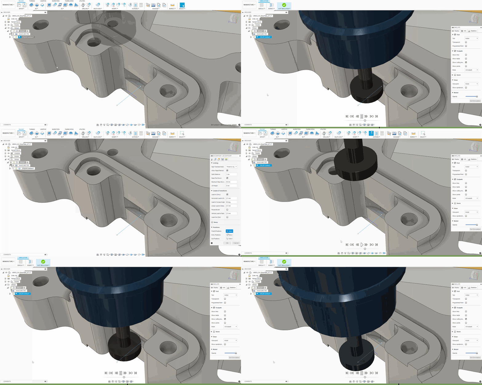
For 2D Adaptive, 2D Pocket, and 2D Contour toolpaths, when using slot milling tools to cut slots where the tool finishes below an undercut. You can now select pre-defined geometry (typically points) and use them to move the tool horizontally to clear any undercuts or overhangs before withdrawing up the tool axis.
Measure from active WCS
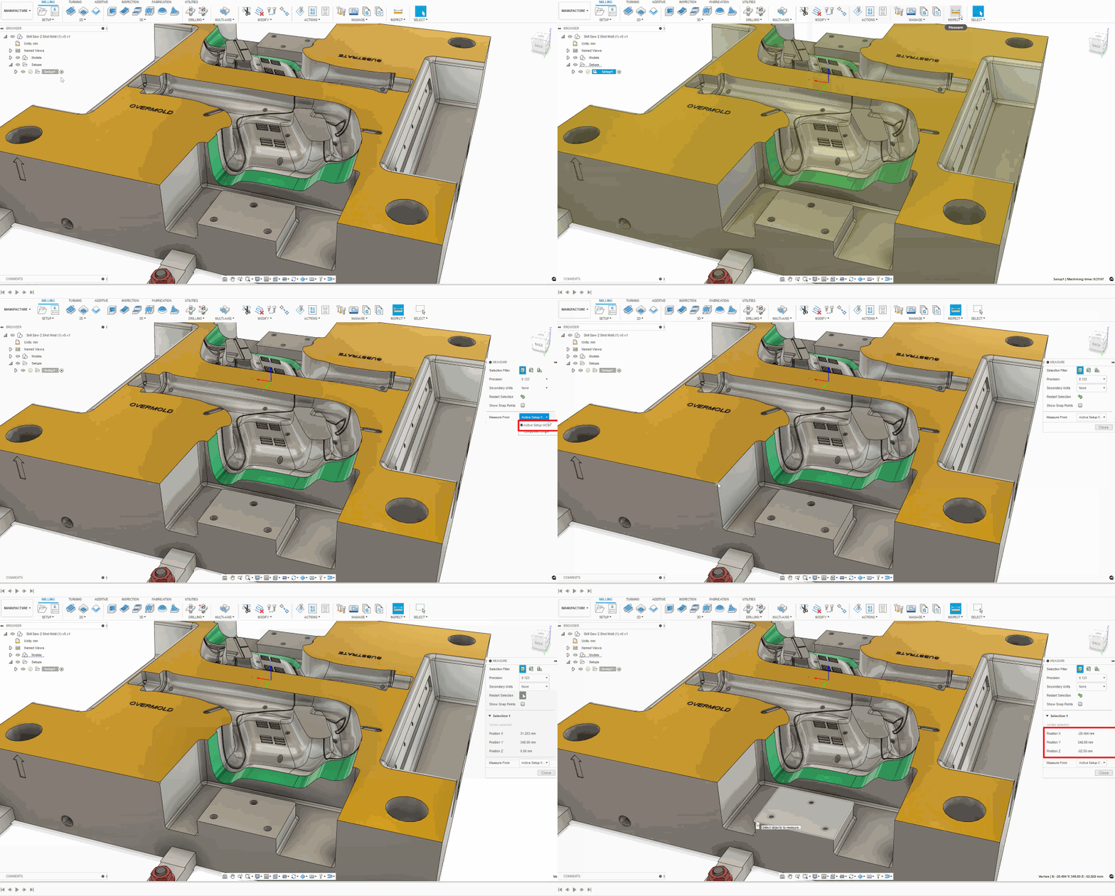
The Measure command now allows measurements to be reported relative to the active setup workpiece co-ordinate system (WCS).
Cusp-height based Stepover/down
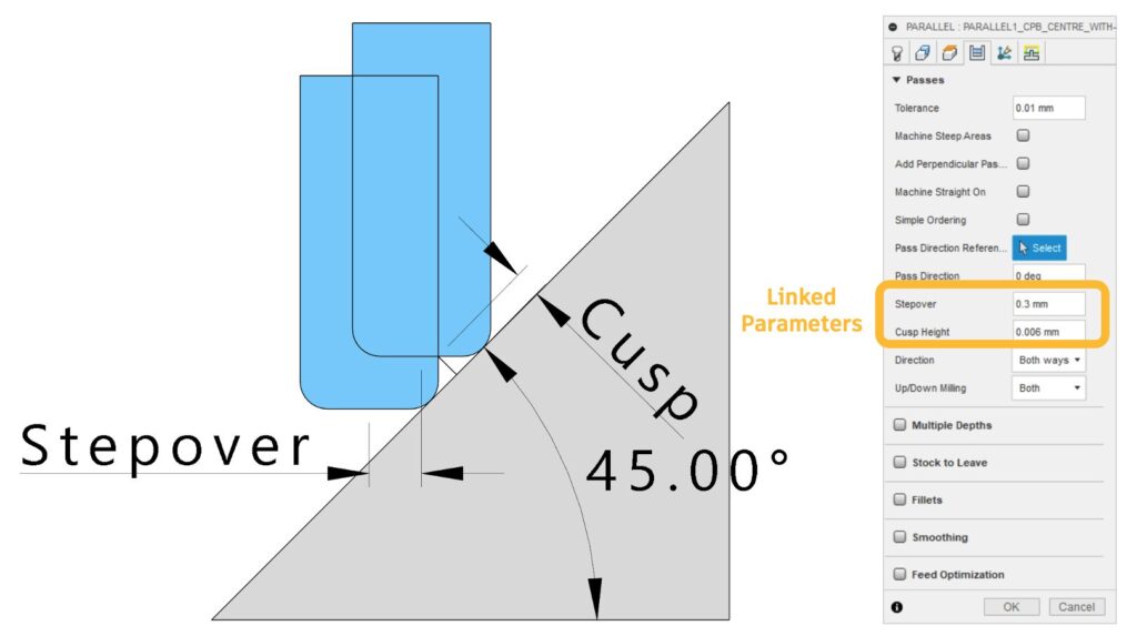
Stepover and stepdown can now be automatically derived from a user-defined cusp height (or vice versa). This option works for most 3D finishing strategies and helps you achieve your desired surface finish.
Learn more about the Cusp Height
Flat machining multiple depths
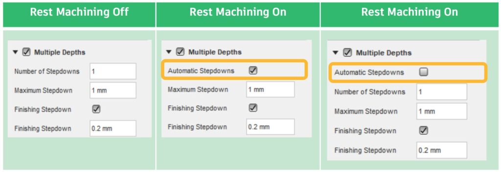
Within the Multiple Depths function of Flat Machining you are now able to specify the Number of Stepdowns.
Steep and Shallow UX improvements
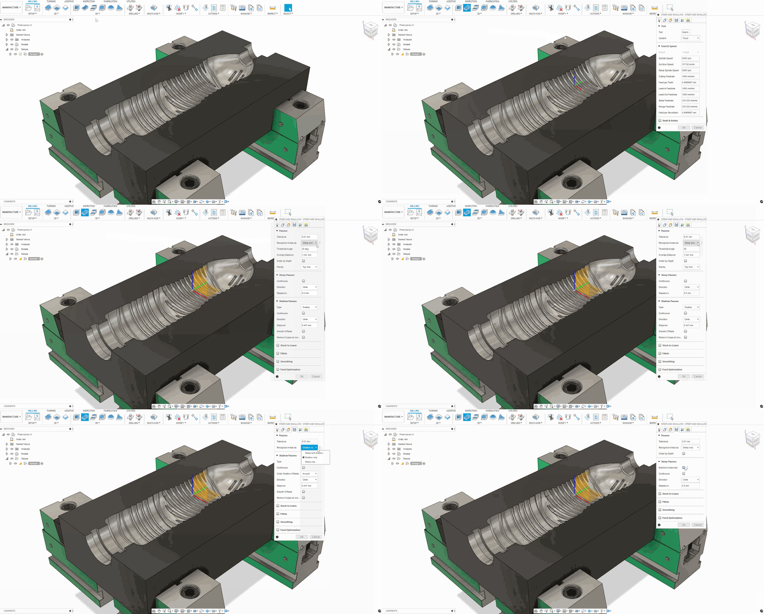
You can now choose whether to machine steep regions only, shallow regions only, or combine both steep and shallow regions (the previous default).
Scallop (shallow region only) can now be ordered inside > out or outside > in.
Blend one way/other way preview
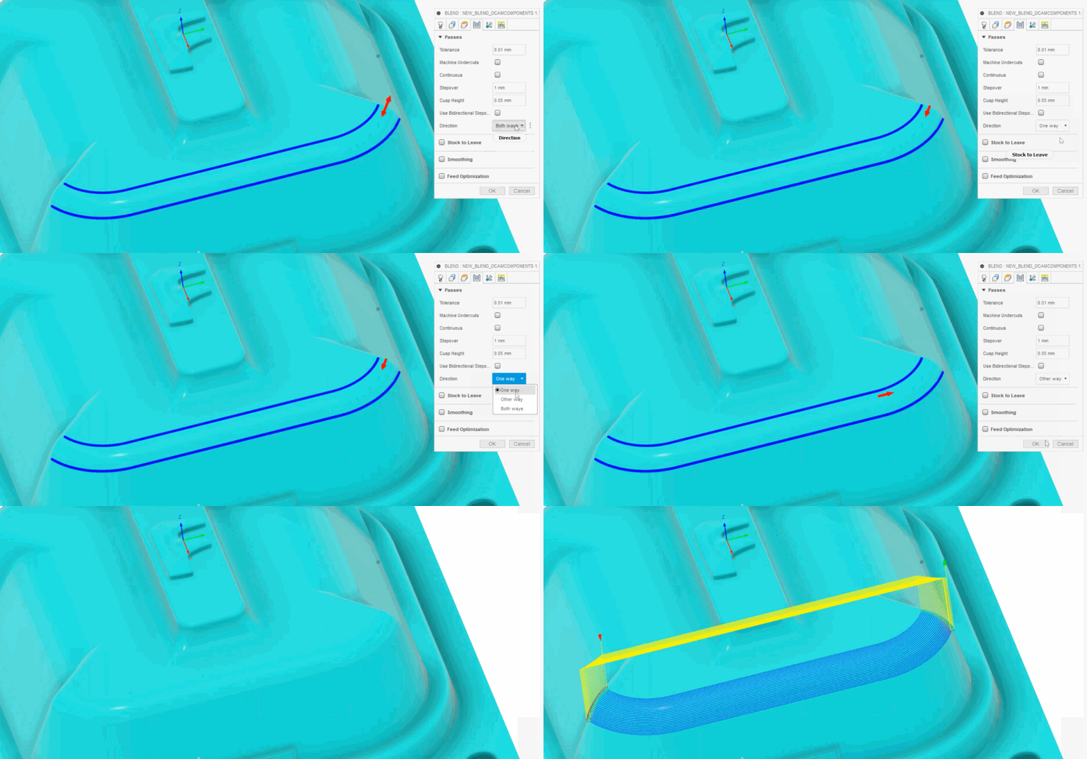
The Blend toolpath now displays a small red arrow to show the cutting direction prior to calculation. The arrow changes when you select “One Way”, “Other Way” or “Both Ways” this means there is no longer a need to guess which direction to use! You will be able to create the right toolpath the first time around every time.
2D Chamfer improvements
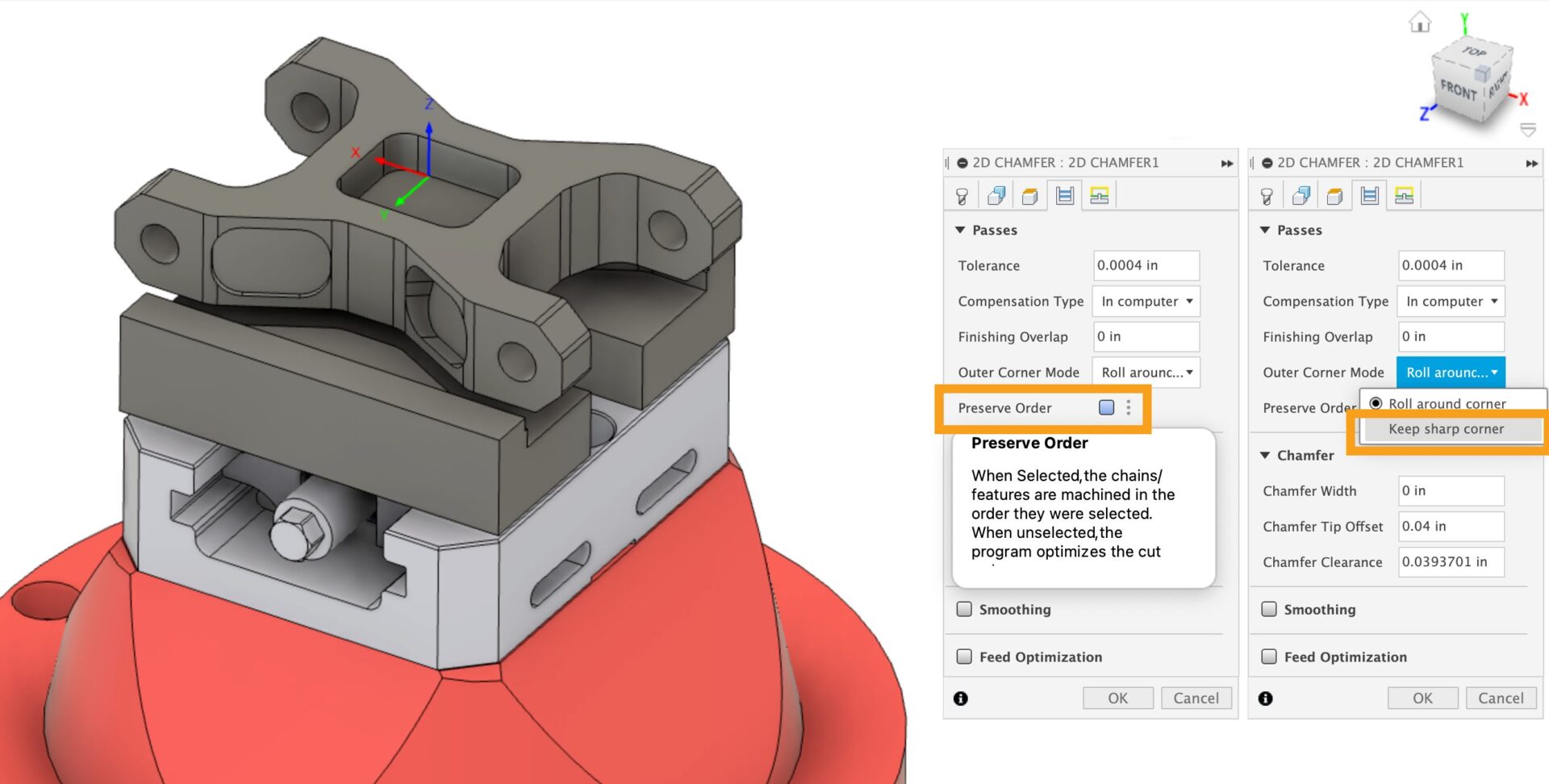
You have a new option to “Keep sharp corner” creates a toolpath that does not roll around the edge, reducing the likelihood that the external edge will be damaged.
Also, a new option “Preserve Order” changes the order of the toolpath such that it matches the order that the contours were selected.
Hide Warning Messages – Now there’s a new option that allows warning messages to be hidden to avoid excess interruptions when programming.
Learn more about how to generate a 2D Chamfer toolpath
Learn more about warnings and errors
Separate “focus” and “active” states for elements

This is to help you identify what you will be copying using CTRL+C we have aligned functionality so that each explicit area selected in the tool library now has a blue banner surrounding it.
Move/replicate the “Remove unused tool” option
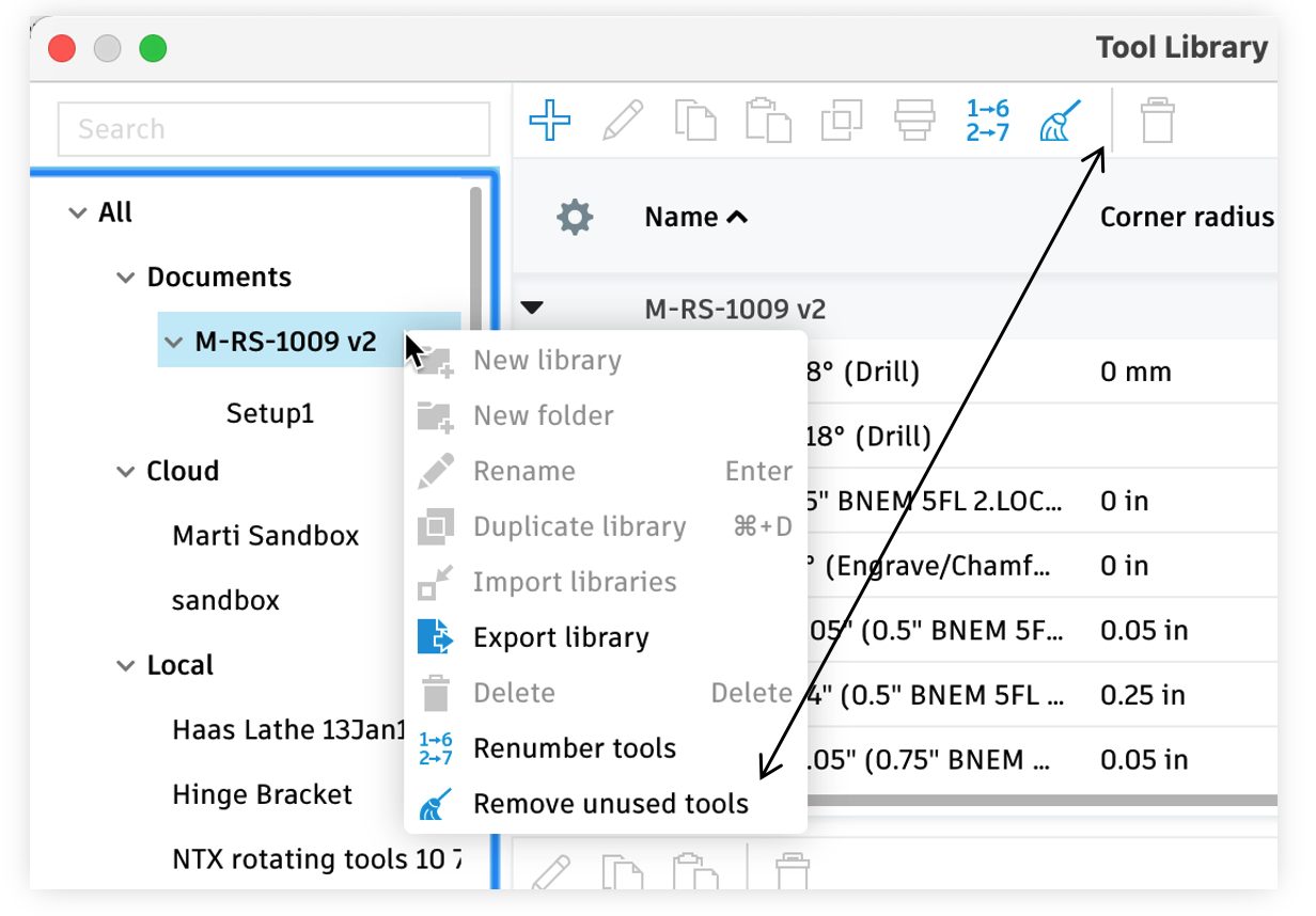
Many of you reported that the Remove Unused Tools function was difficult to find, so to help increase discoverability, we moved to the main tool list banner.
Identify pasted tool in the main tool list
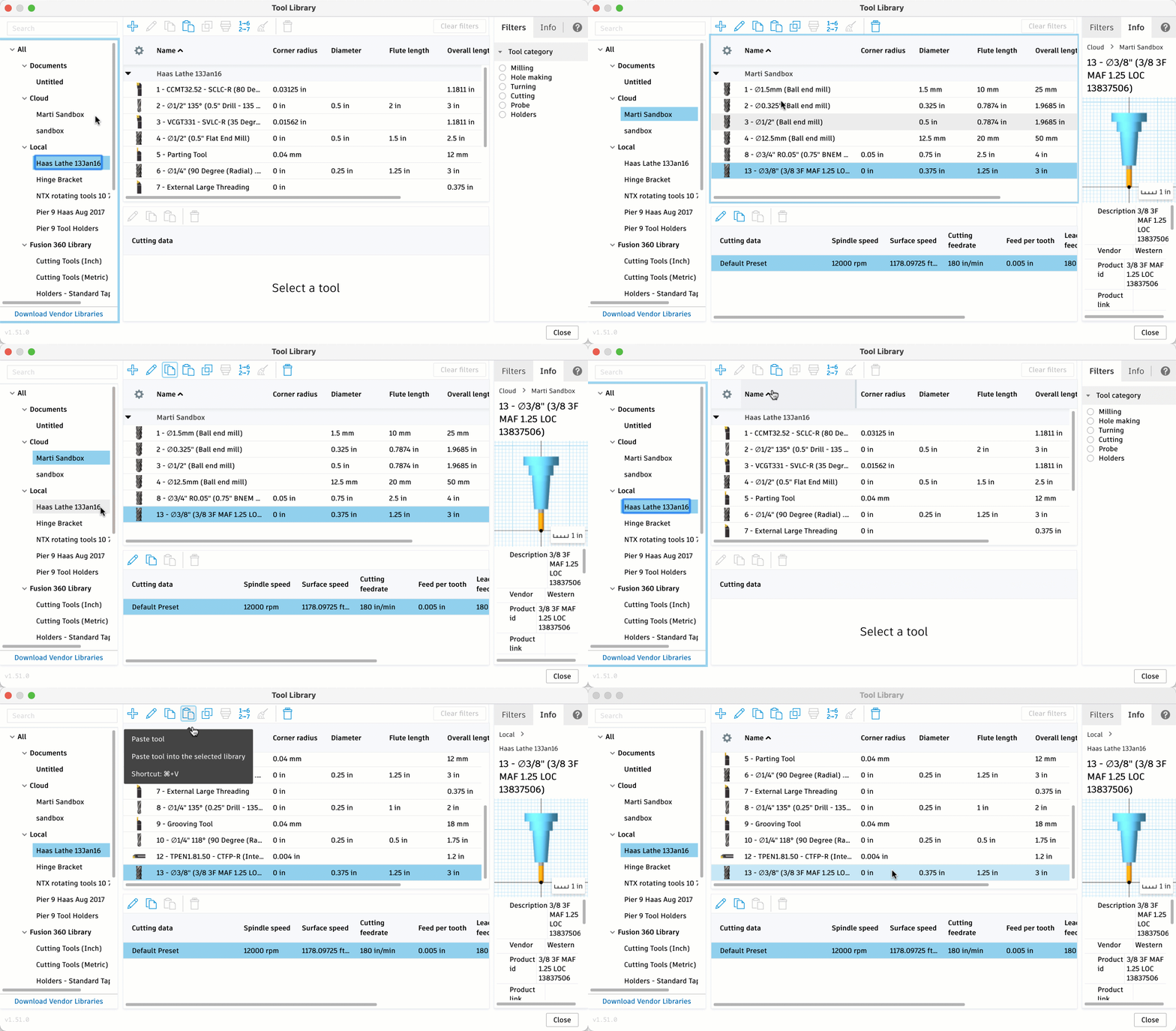
When pasting tools into a large list, it’s easy to lose where you are. That’s why pasted tools will now appear highlighted in the destination library.
Download vendor libraries
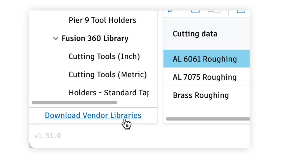
Now there is a link in the tool library where you can download vendor libraries; this will give you greater access to vendor tools.
Avoid creating duplicate document tools when selecting from another library
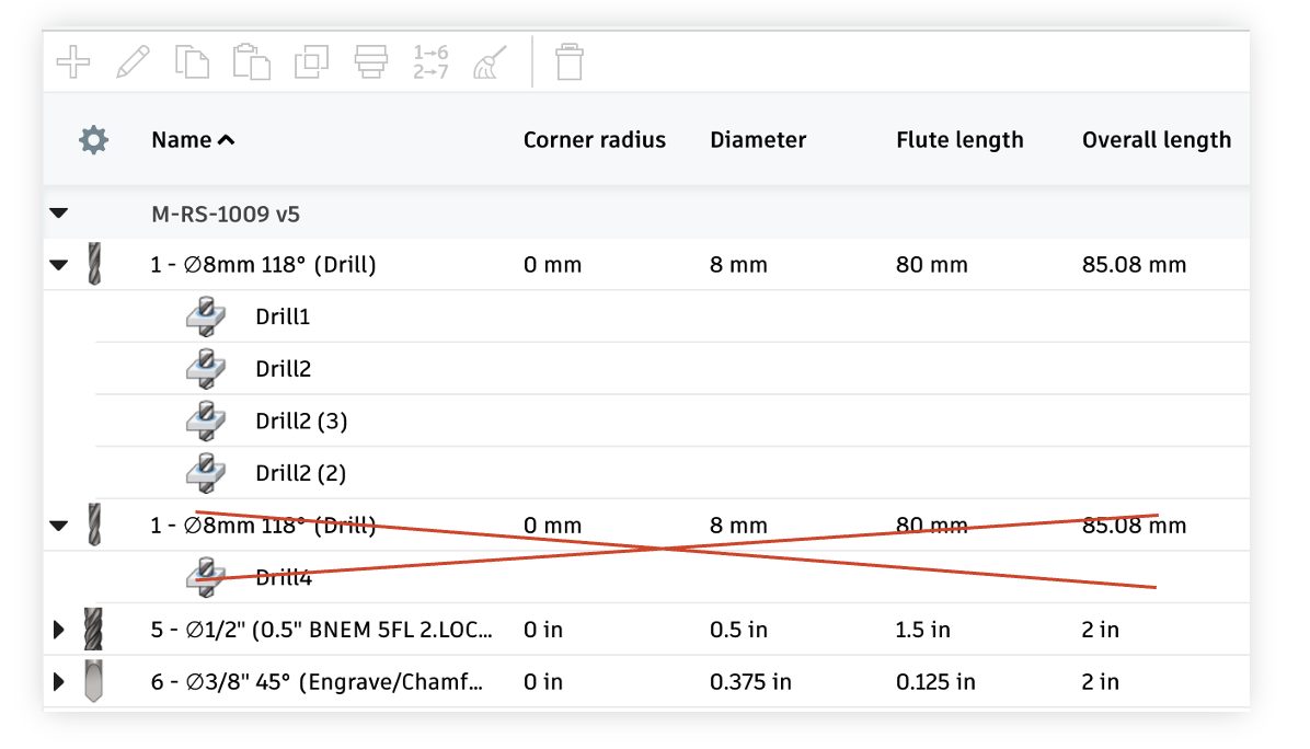
Previously, if you entered the tool library from an operation and selected a tool that was already in the document, a duplicate instance would be created which caused many confusing downstream issues. Now Fusion 360 will no longer do this – it will just use the tool in the document.
Identify reference tools in the tool list

Reference tools used in an operation can now be visually identified in the tool library making tool management in the document library a breeze.
Improved sample libraries in the Tool Library – We updated the Sample libraries to contain all tool types with default values included.
Column Width in Renumber Tools Dialog – Column Width in the Renumbering Tools Dialog now supports a width up to five digits! This update will help you expand your capabilities when renumbering a new tool number.
Learn more about the Tool Library
Manual Inspection
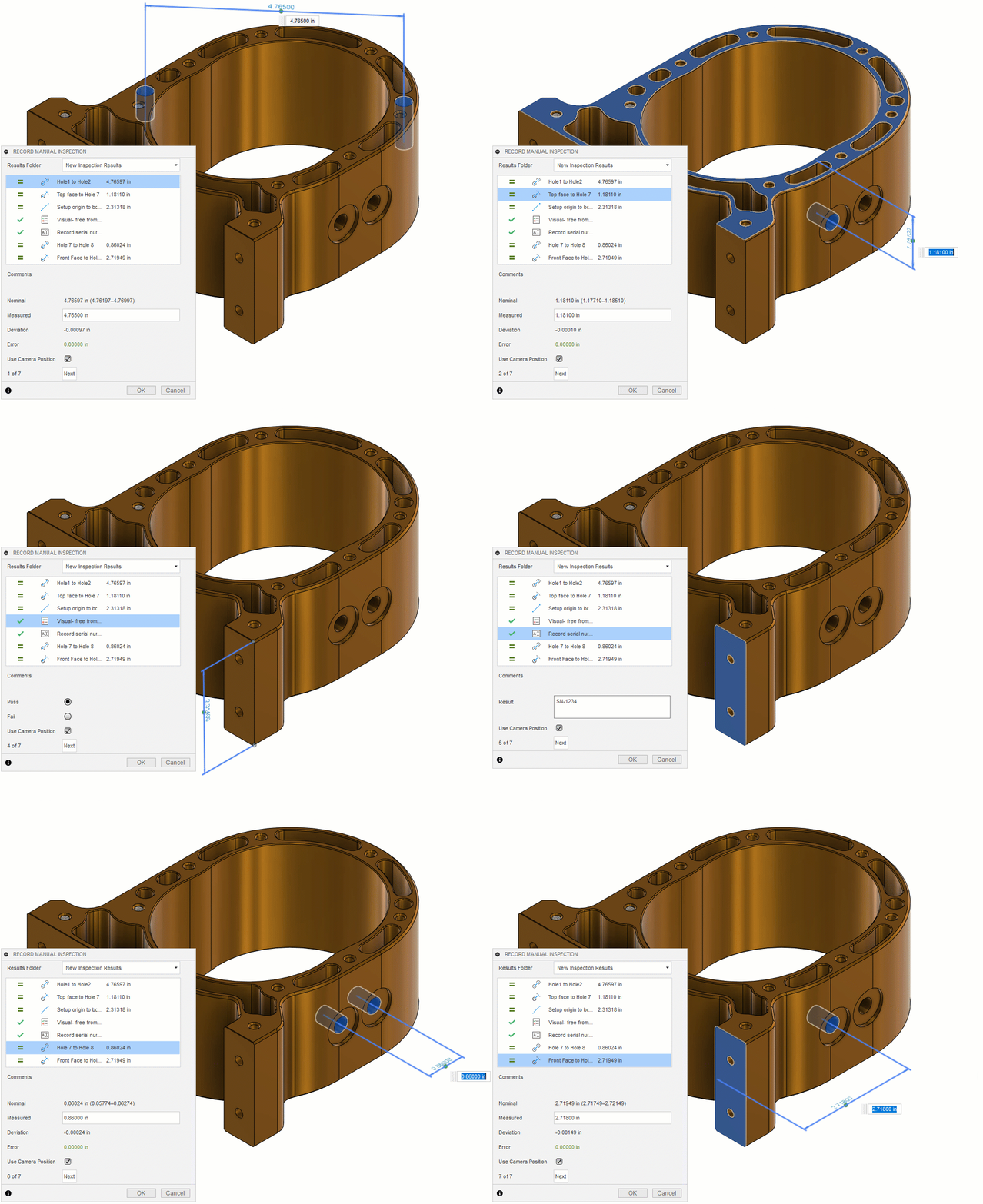
We improved the existing Manual inspection tool and added new manual distance options. Now you are able to inspect:
Probing
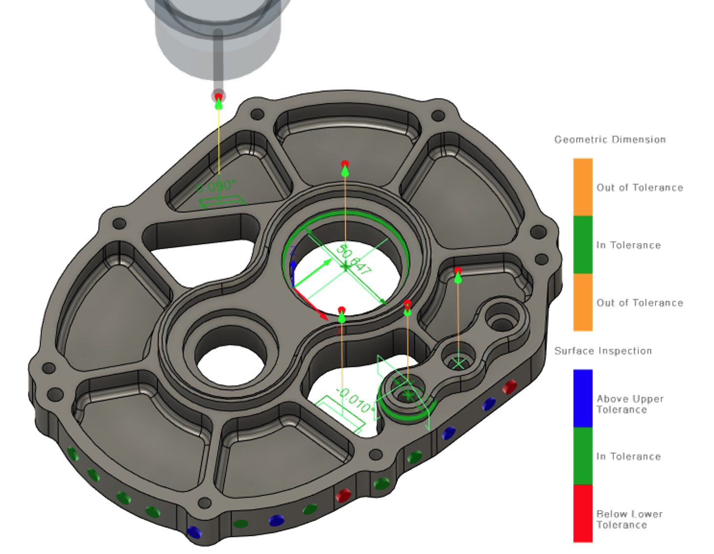
New options affecting probe path creation and reporting include:
Threading tool versatility

Threading tools can now be used for Single Groove toolpaths and Chamfer toolpaths.
Visibility controls
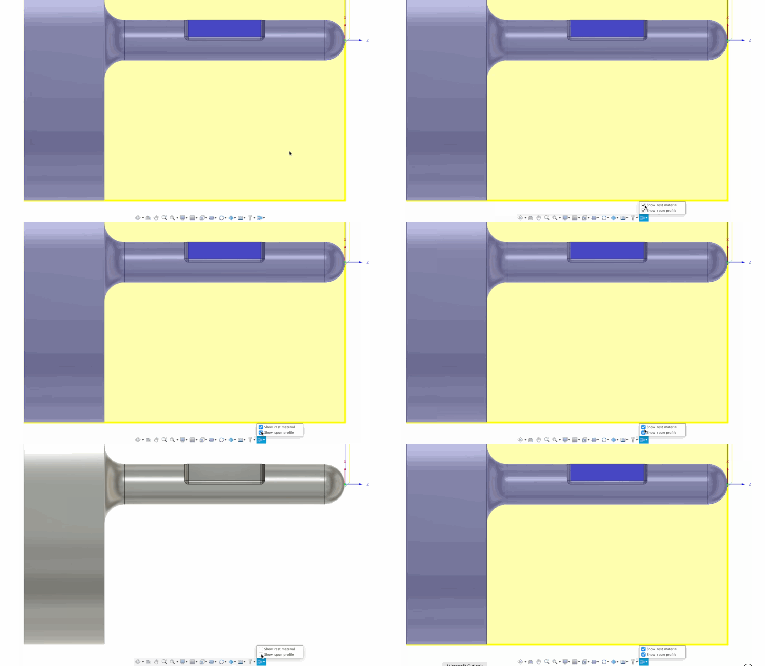
New view controls can now be used to show/hide the Spun Profile shape and Rest Material. Learn more.
Show toolpath data dialog
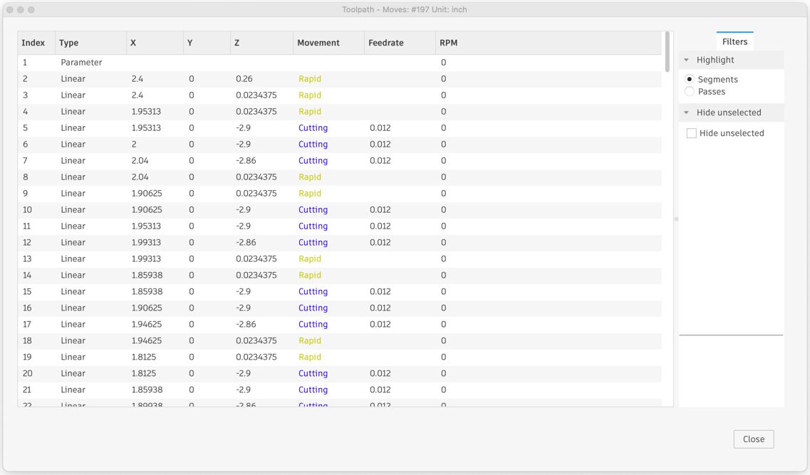
The interface now correctly shows Z and X coordinates instead of just X and Y.
Spun profile calculation
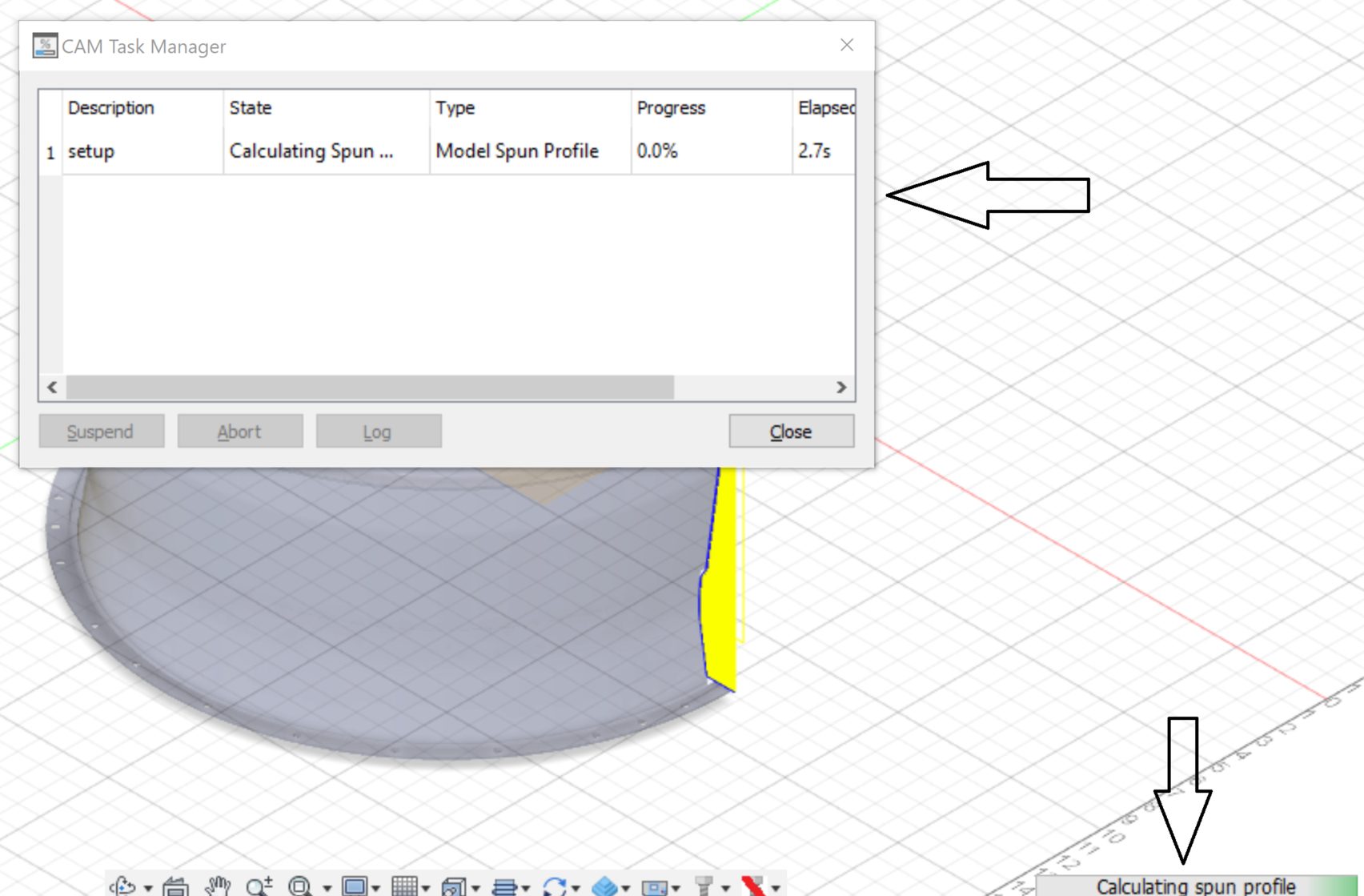
Now uses multi-threading for improved speed and stability and displays a green progress bar.
Learn more about turning
Advanced Nesting updates
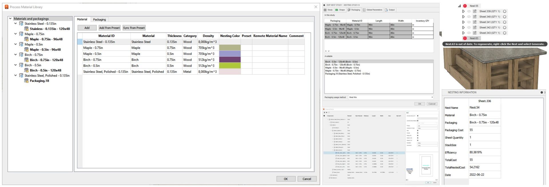
Arrange updates
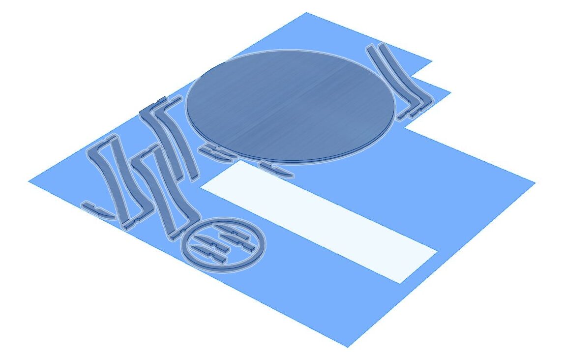
FFF Toolpath simulation now can display Print Speed

A new type to display the print speed has been added to the FFF toolpath simulation. Displaying the printing speed will help you optimize your jobs for printing time or detect potential issues with oozing or stringing. To activate the new display type, create an Additive setup with your FFF printer, generate and simulate the toolpath and change Display Type from “Toolpath Type” to “Print Speed”.
Learn how to simulate an additive toolpath
Print Settings are now only stored on the online Machine Library

We have announced that print settings are now stored in Fusion 360’s online machine library. To complete this initiative, we have removed the print settings from Fusion’s installation directory. You can either download the print settings from the website, or you can access them directly within Fusion 360 if you have the following technology preview enabled.
Learn how to work with print settings
Improvements to additive support structures
The focus for support structures in this release was to improve support generation for the SLA process. You now have more control over the support structures in critical areas of the part. The new support action “Edge with Bar Support” will create support bars along the edge of a part. This will help with stability of the part during printing while ensuring the outer contour is built accurately. In most cases you should use this new action in combination with the Bar Support action. You can find the action in your additive SLA or MPBF setup under the supports section.

However, it is important to keep in mind that the stronger the support structures, the harder it will be to remove them once the build is completed. Therefore, we have also worked on improvements that will help with removing the support structures from the part. For SLA it is common to use a pad on the bottom that connects the support structures with the build plate. However, getting under this solid block of material with a tool, may be hard when trying to separate it from the build plate. Therefore, the pad setting for bar supports and baseplate support was expanded to also allow a negative taper angle. The new setting can be found under the General tab for Baseplate Support and under Bar Support/Bar Properties/Pad on Platform.

The final improvement made to ensure our support structures are better suited for SLA printing was the new settings under “Bars on Global Features” for Lattice Volume Support. The new options “Down Oriented Points” and “Sharp Edges” make sure that the lowest feature of the part is always detected and supported since it is otherwise easily washed away in the resin tray.
Learn how to add an Edge with Bar Support
Learn how to add a Base Plate Support
Learn how to add a Lattice Volume Support
Library updates for templates, additive machines, print settings
In addition to these support structure improvements for SLA, a new template with optimized defaults for part orientation has been released. The template is intended for orientation of larger parts in the build envelope. The part will be oriented in a way that reduces the surface area of each layer. This minimizes the amount of contact it has with the tray, which could lead to the part being detached from the build plate. Find the template in the template library under orientations.
The other new templates are providing support defaults for One Click Metal MPrint+ machines
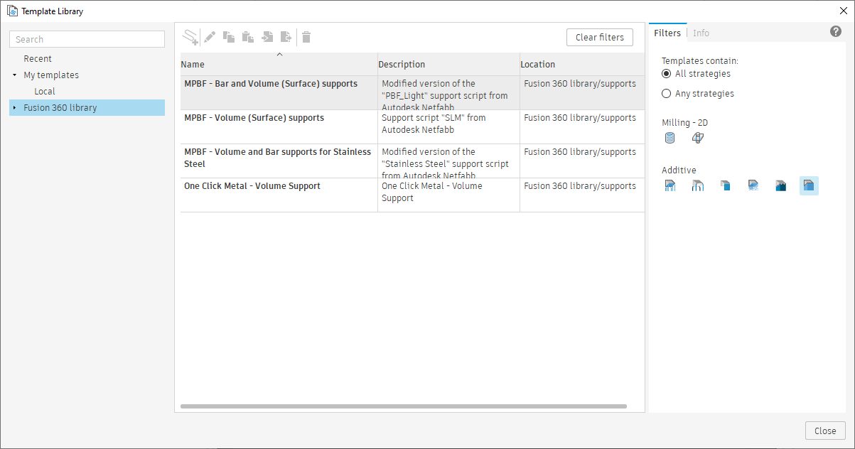
These have been validated and tested by One Click Metal. Find the templates in the template library under supports.
The machine library now includes several new machines that support different processes: We have added a generic SLS machine with 3mf export that can be used as template for adding SLS machines that are not in the machine library yet. To decrease the chances of that happening, Nexa3D QLS820 and NXT Factory QLS350 SLS machines have been added to the machine library. Furthermore, there is now support for EOS M100 and Stratasys Origin One machines.
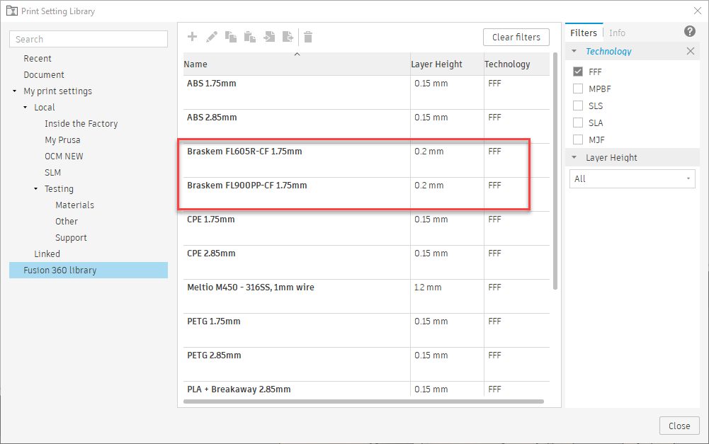
Two new print settings for Braskem FL900PP-CF and Braskem FL605R-CF have been added to the Online Print Settings List.
New material file and result type for Additive Simulation
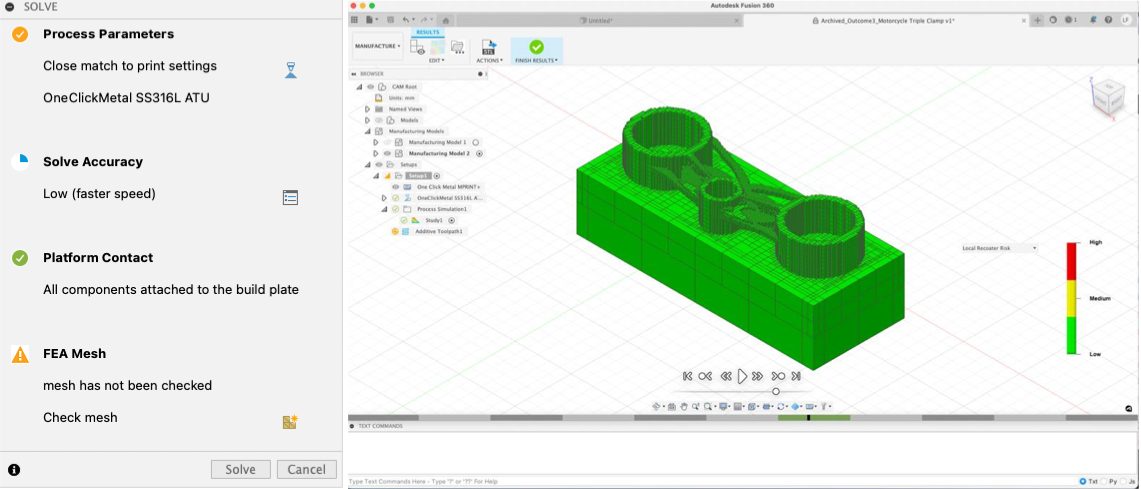
There is a new material/ parameter profile (PRM) for One Click Metal 316L print settings. Simply create a new setup with a One Click Metal machine and select a 316L print setting. When setting up the additive simulation it will automatically match the new PRM file to the print setting.
The second improvement introduced a new result type called “recoater risk”. Since warping is a serious issue in MPBF Additive, it is important to understand whether a part is warping up and runs at risk of hitting the recoater blade, which would be a threat to the entire build.
New CAM Simulation Tab
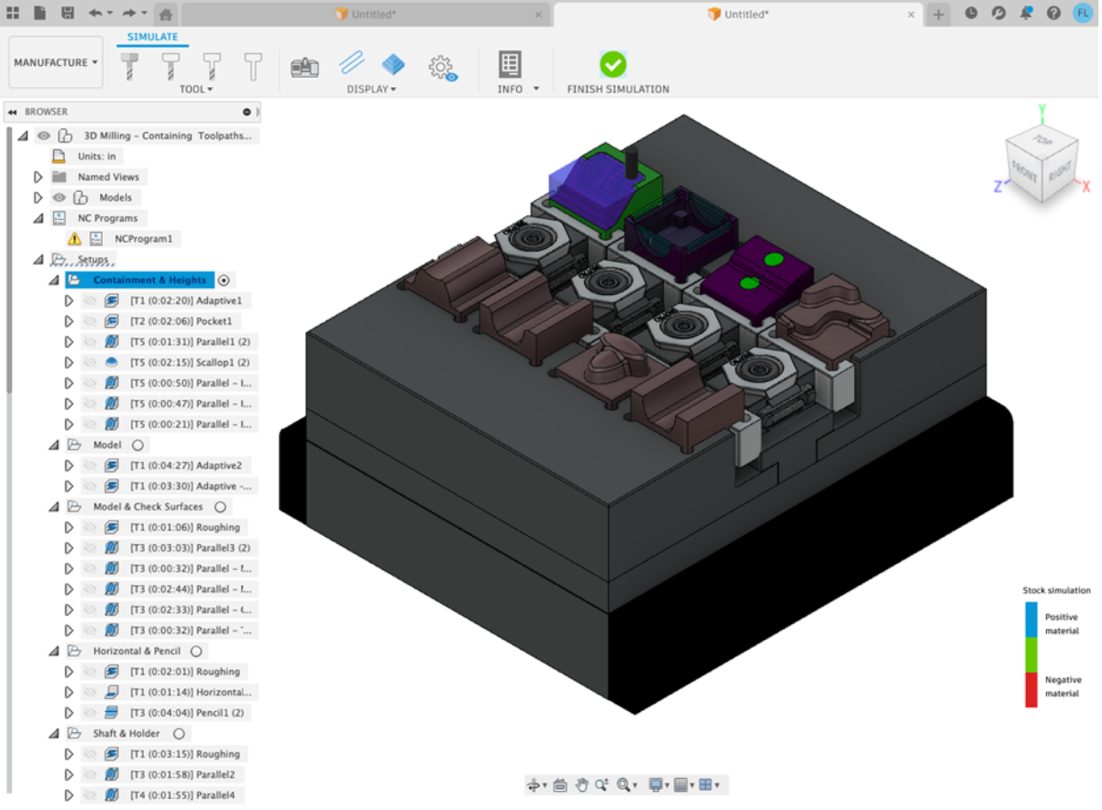
This is the first in a series of updates to improve the simulation capabilities in Fusion 360. A new tab and improved simulation behavior results in more intuitive workflows, paving the way for future updates that will see the emergence of technology currently available in the CAMplete family of products. These updates impact everyone using the manufacturing workspace in Fusion 360 (not just those with access to the Machining Extension).
The Simulation Tab includes familiar icons that can be used to control the view status of tools, machines, toolpaths, and stock. Additional icons provide quick access to more advanced display options, as well as information relating to the outcomes of simulations.
In addition to interface changes, simulation behavior has been enhanced. As an example, you can now create section views whilst still in simulation avoiding the need to ‘re-compute” the stock simulation. Prior to this change, you would need to leave simulation, create the section view, then re-enter and recompute simulation to get the same result (sometimes taking many minutes).
In future releases, we hope to enhance the error reporting to provide additional information relating to collisions, travel limits, and more. In addition, CAMplete technology will be integrated into Fusion 360, allowing G-code to be displayed whilst simulation is running, so you can see line-by-line what actions your machine will perform.
Learn how to simulate manufacturing operations
Show spindle direction arrows
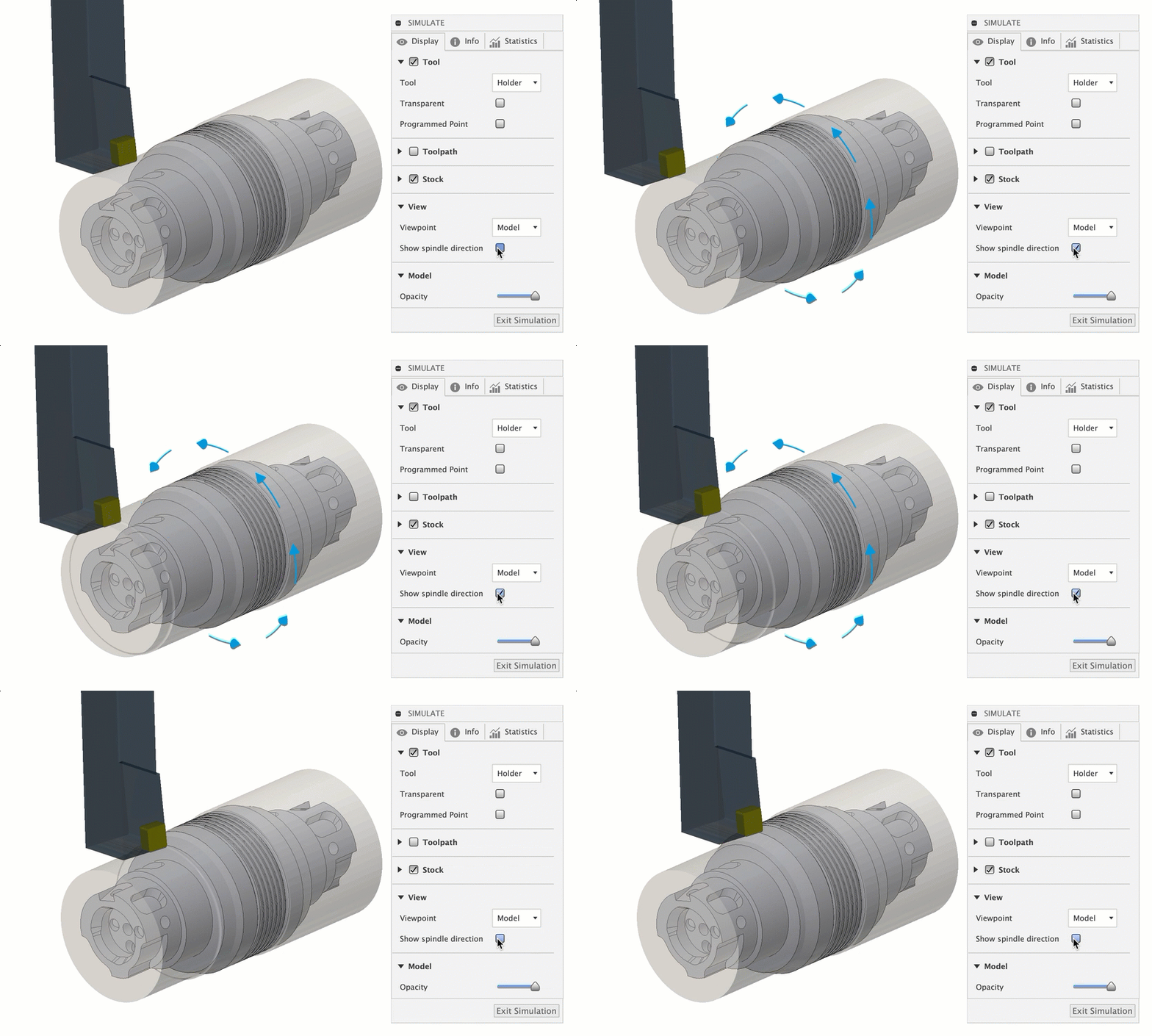
A New option displays arrows to represent the direction that the turning axis rotates.
Section View during simulation
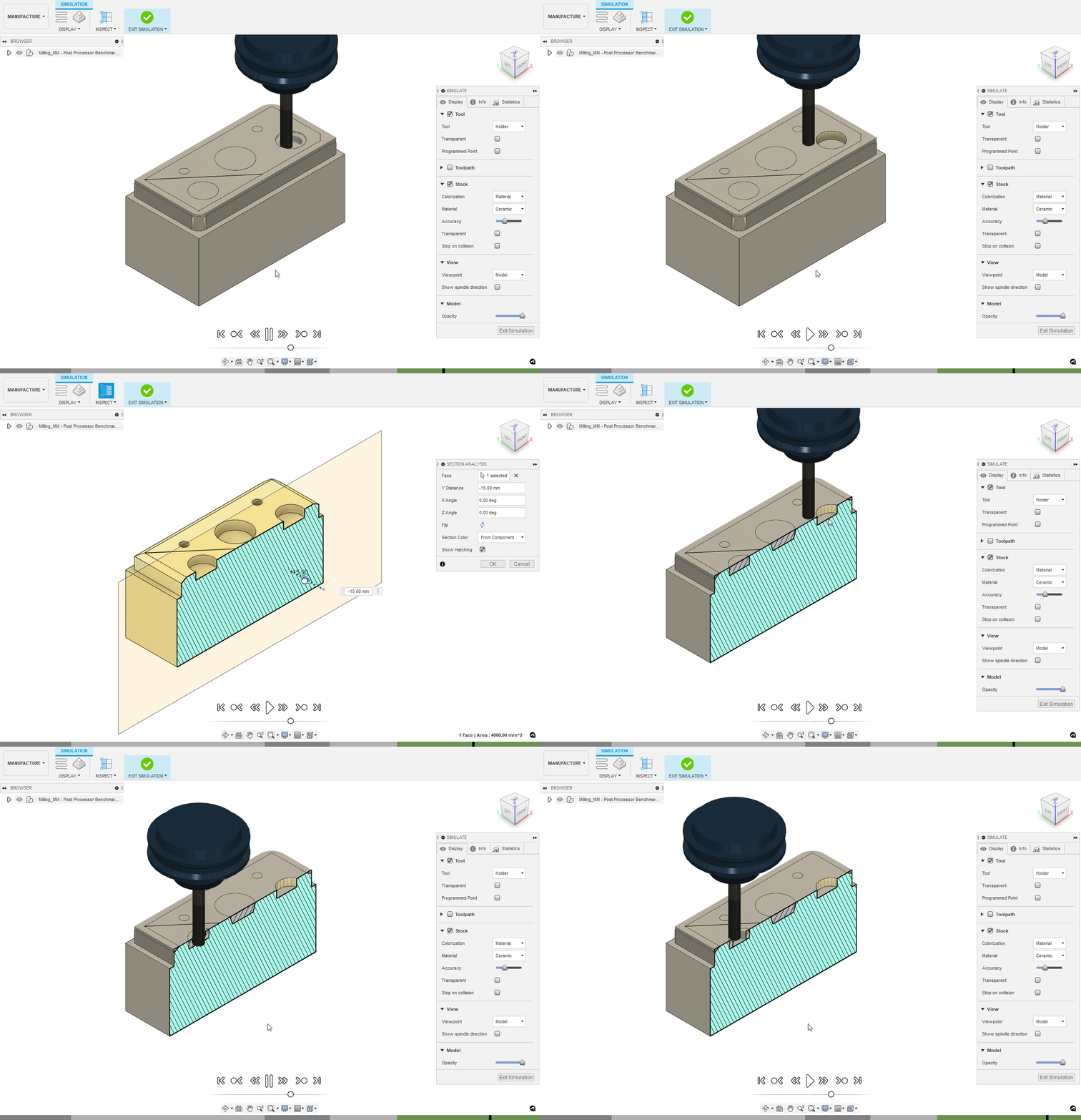
One of the quick things we added to this mode is the ability to add section views whilst already in simulation. This means you can section up the view without needing to leave simulation and lose the computed stock
Construction geometry
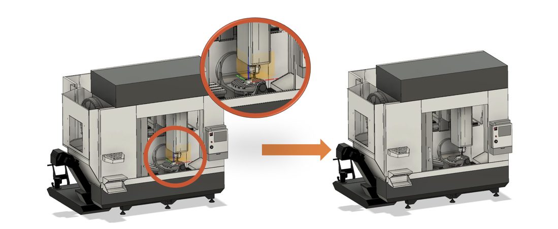
When building a machine, you can now select and hide construction geometry from view, resulting in a cleaner looking simulation.
Jogging UI updates and new “home” icons
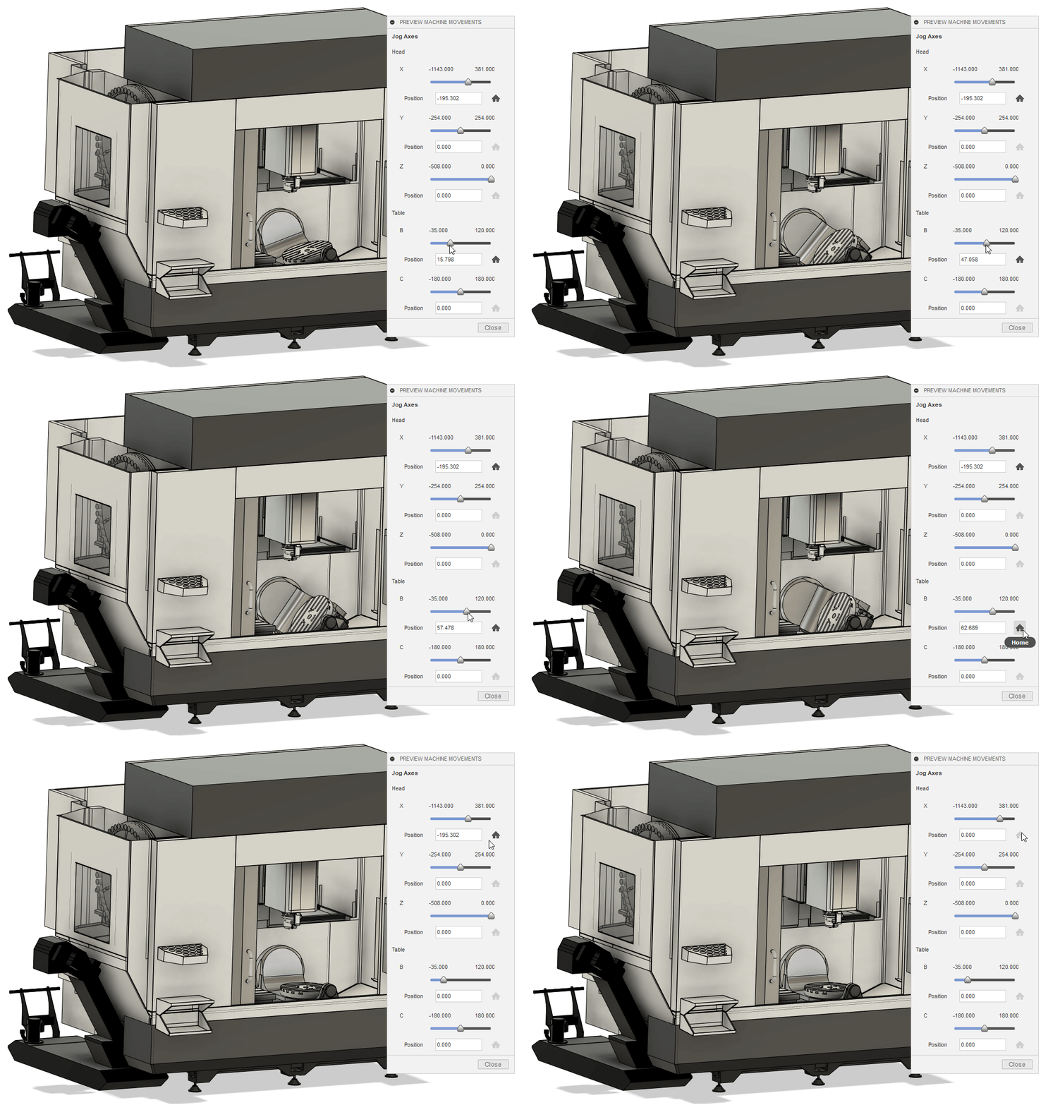
The jogging interface now displays the current position of the machine’s axes during jogging commands.
New home icons have been added to the jogging UI to reset each axis to its home position. Separate icons exist for each individual axis, with another master home icon that resets all axes.
Selecting center point on non-cylindrical parts
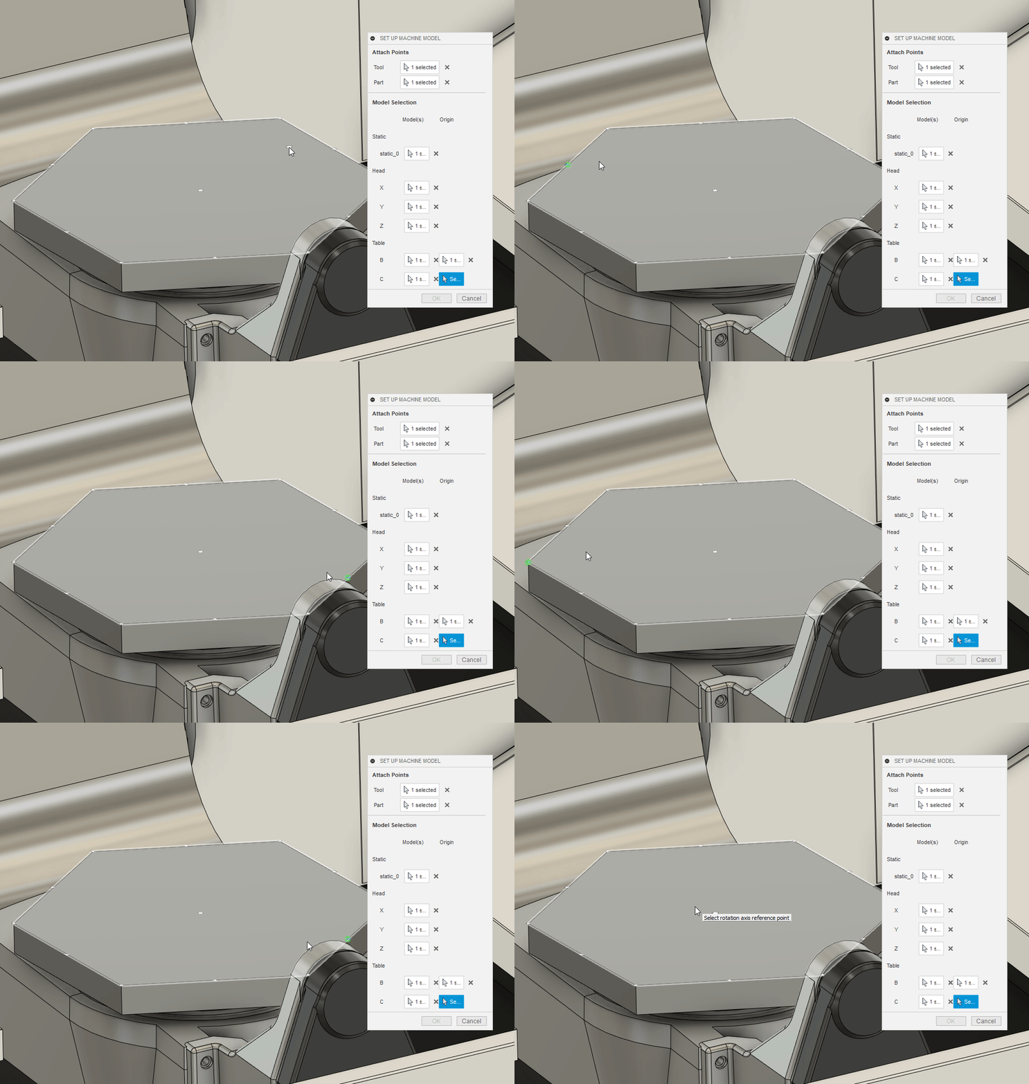
Now you can hover over a non-cylindrical part on your machine and snap to the center points of the face, just like how you would place a Joint/Joint Origin on component faces.
Non-TCP machine simulation support – machines without TCP control can now be simulated in Fusion 360 .
Learn how to simulate a toolpath
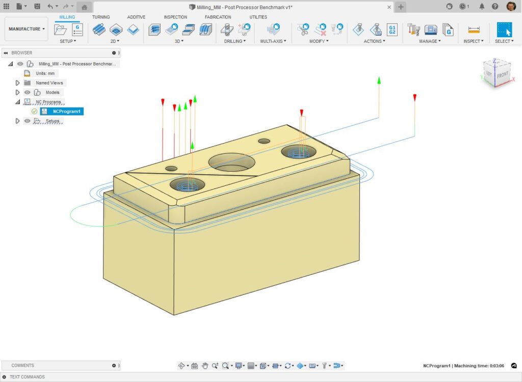
Properties for individual operations – post processor files can now be edited such that individual properties can be enabled at the operational level, allowing them to be revealed and edited within the Fusion 360 interface
Draw toolpaths on NC program selection– when a NC program is selected, Fusion 360 can (optionally) display the toolpaths that it contains in the main 3D interface.
All Generic Post Processors now make use of the probeWorkOffset variable and drill cycles that feed out of a hole do now respect the retract feedrate.
We’ve improved post processors from the following machines:
We now have Machine simulation models for this following machines:
Learn how to post process
See full list of what’s new in Post Processors
UX Pattern Consistency

We made multiple updates inspired by the pattern UI in the Design workspace, including:
Expression UI improvements
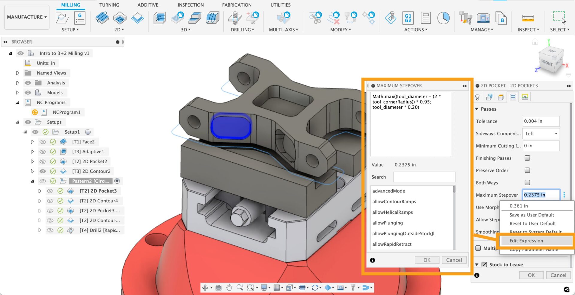
In the spirit of consistency, we also tweaked various expression UI elements so that they behave more like the rest of the other workspaces, including:
Machining Time is back
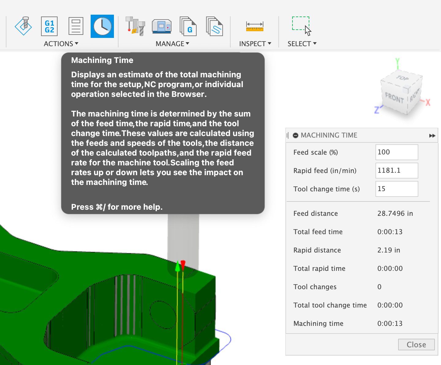
Machining Time is back! We’ve reinstated the command back into the Fusion 360 UI including the following improvements:
The July update sees a significant expansion in 5-axis programming capabilities offered in the Fusion 360 Machining Extension. Prior to this release a small number of 3D finishing strategies offered limited 5-axis options, with only one (Steep and Shallow) offering full 5-axis capabilities. With the July update, many more strategies now support additional 5-axis options to control the tool axis via a user-defined point or curve. Additional strategies (Corner and Inclined Flat), that also support 5-axis machining, are also getting ready for inclusion in the Insider Preview program. The development team continues to work on adding 5-axis support for the remaining 3D finishing strategies.
Learn more about the 5-axis options
Fusion Data API is now out of Preview
We are very excited to announce that the first set of capabilities for the new cloud-based data API has been released, allowing you to traverse assembly hierarchy and read additional component properties even for “internal” components.
Previously you could access Fusion 360 file information via the Forge Data Management API and perform translation and viewing using the Forge Model Derivative and Forge Viewer APIs, respectively.
We have big plans for this API so expect to see more information and enhancements coming over the next few releases. To see more of what it can do now, check out this blog post.
API Improvements
Here are the new capabilities that have been added for this release. See the API Documentation What’s New Page for more details.
Bommer Update
Our friends at Bommer updated their add-in as well, so if you’re using it with Fusion 360, be sure to update your version of Bommer to the latest one!
Join us for an exclusive 60-minute live event with Fusion 360 experts. We’ll cover all the latest features and functionality in Design & Documentation, Manufacturing, Electronics & Generative Design. We’ll show live demos of the latest improvements, show off some tips & tricks, and open the floor for plenty of LIVE Q&A.
We have 2 sessions on Tuesday, July 19, 2022 for you to choose from, both identical in content, just at different times. Click the links below to sign up. Looking forward to seeing you there!

We started this program last summer with only a handful of users, brave enough to live on the bleeding edge with the Insider build running on their machines. Now the program has grown to 2000+ members, helping us catch issues and using the Insider build in their own unique ways. They are also the first to know what’s coming in the next update, and are able to try it in their Insider builds, 3 weeks before it goes out to the general public. If this sounds like something you want to be a part of, sign up now to become a member!
By clicking subscribe, I agree to receive the Fusion newsletter and acknowledge the Autodesk Privacy Statement.
Success!
May we collect and use your data?
Learn more about the Third Party Services we use and our Privacy Statement.May we collect and use your data to tailor your experience?
Explore the benefits of a customized experience by managing your privacy settings for this site or visit our Privacy Statement to learn more about your options.