& Construction

Integrated BIM tools, including Revit, AutoCAD, and Civil 3D
& Manufacturing

Professional CAD/CAM tools built on Inventor and AutoCAD
3 min read
Everyone has to start somewhere…but it’s where you end up that matters. As an ex-SOLIDWORKS user, I was ecstatic to hear some of the developers talk about sheet metal functionality making its way into Fusion 360. If you have taken a tour of the IdeaStation, you may have noticed that the most voted for idea is sheet metal functionality. The Fusion 360 team has listened and I was able to get a sneak peek of this highly anticipated tool set.
So I opened my machinery handbook and flipped to the gauge table and bend allowance chart. Then I did what any engineer would do, jump in head first! Fusion 360 has all the necessary tools to specify different rules for your sheet metal parts (thickness, bend radius, corner relief, etc.)

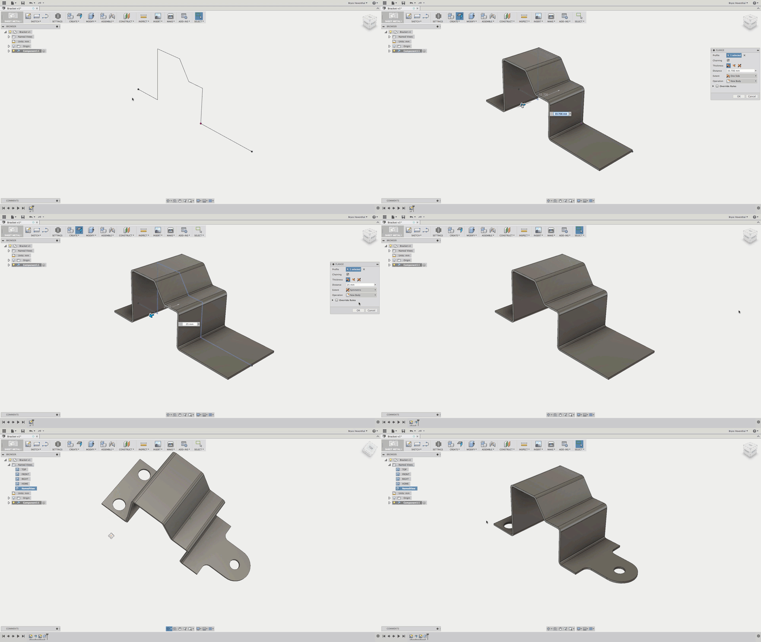
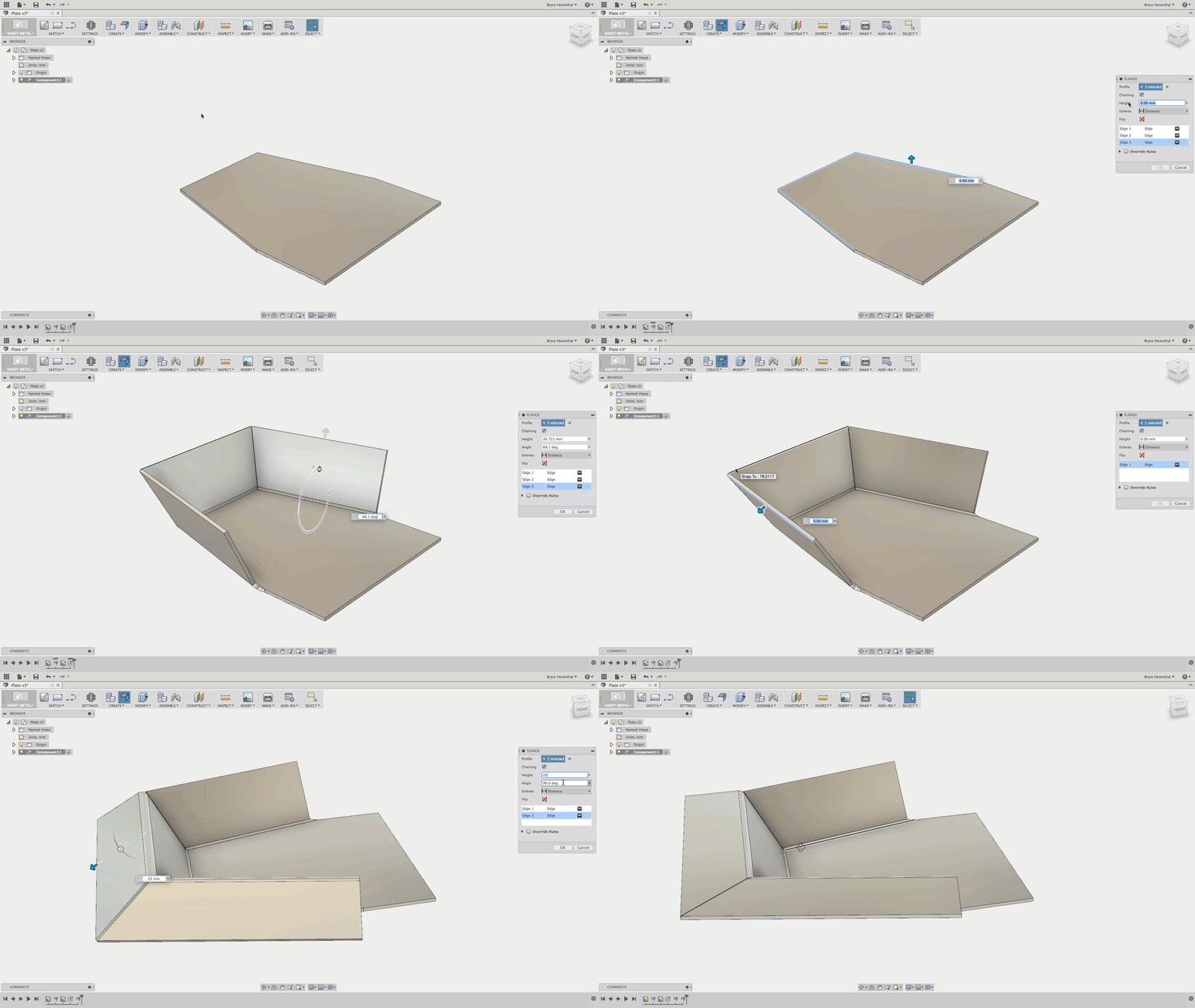
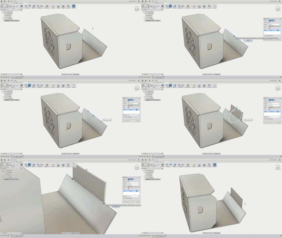
Now, here is the fun part…actually making some sheet metal. I started by creating an open sketch, then I went to see where the base flange, miter flange, and edge flange tools were located. It was then I realized there was only ONE FLANGE command. This couldn’t be right, I spent all those years being trained on the appropriate time to use every different flange command. After further testing, the flange command worked for each scenario. The flange command was aware of the item being selected and the property manager would change depending on the item being selected. Not only does this help people learn how to use the sheet metal tool quickly, after a while I found myself just using the repeat last command (right click>drag up) over and over. This tool reminded me of the press pull command in Fusion 360, which turns into extrude, offset faces, or fillet, depending on the item being selected. How long until a CAD tool is smart enough to suggest the correct command? I suppose that is the “Computer Aided” in CAD.

The one flange for all flanges command is sweet, but I was surprised to hear that some of the more sophisticated tools to automate the creation of complex sheet metal parts would not be in at launch. This isn’t to say there aren’t “workarounds” to create features such as hems, cross-breaks, and joggles, they will just take a few extra clicks. Since Fusion 360 updates so frequently, I am sure we will see some of these automated features in the future. This is where feedback on the IdeaStation is key to drive the tools that come next into Fusion 360.
After I designed a multi-body sheet metal part with a variety of flanges, cutouts, and corner treatments, I went to flatten. It’s just flat out cool, but how does Fusion 360 help me? Since Fusion 360 stores the data in the cloud, the flat pattern is always available and up to date. The sheet metal flat pattern can be viewed just like the simulation results, renderings, and CAM toolpaths in A360 in a web browser. I can’t tell you how many times, I had to VPN into a server, locate the correct sheet metal design, flatten, and save out DXF just to send one design to a water jet. Now, I can just open up A360 and I can download the DXF from anywhere in the world.

So what’s next? Fusion 360 promises to integrate the product development process from design to production. The sheet metal toolset, will do just that. Rather than being a tool for Design to Flat Pattern, Fusion 360 will be a tool that integrates design to manufacture. I can simply switch over to the CAM workspace and start creating toolpaths to cut my sheet metal parts on my water jet. Of course, if I update a flange length or change a bend radius, my toolpaths will update. Now can Fusion 360 take it a bend further (see what i did there)? It would be MONEY if Fusion 360 also included a nesting tool. Find me a manufacturer who doesn’t want to save time, money, and scrap and I’ll show you company going out of business. Luckily, I learned Autodesk owns a nesting tool. Now, it’s not a matter of “if this will make it into Fusion 360, but “when” ;].

By clicking subscribe, I agree to receive the Fusion newsletter and acknowledge the Autodesk Privacy Statement.
Success!
May we collect and use your data?
Learn more about the Third Party Services we use and our Privacy Statement.May we collect and use your data to tailor your experience?
Explore the benefits of a customized experience by managing your privacy settings for this site or visit our Privacy Statement to learn more about your options.