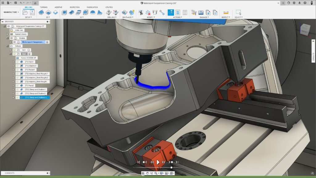
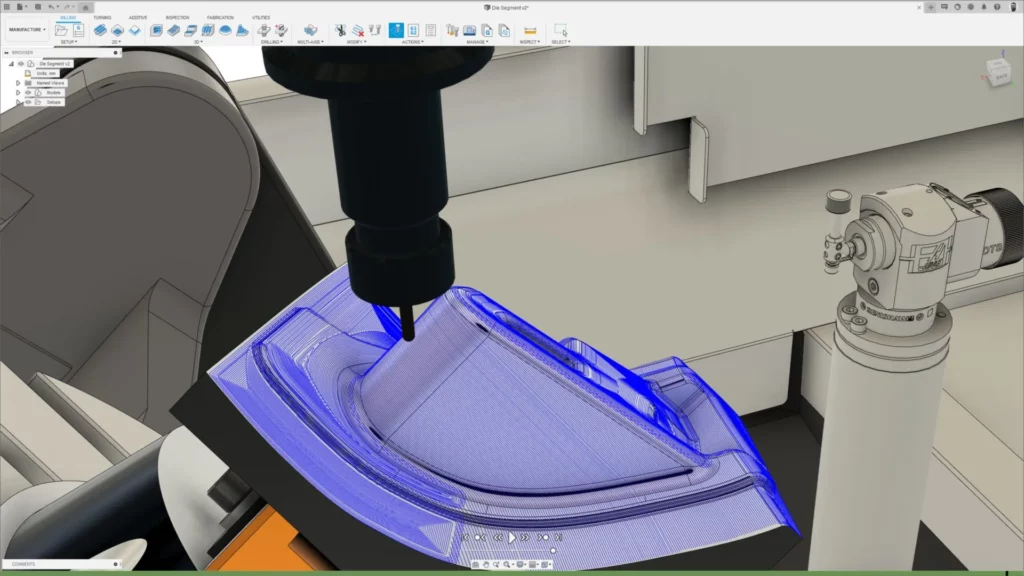
In this article, we’ll do a deep dive on how 5-axis machining works in Fusion 360 — from selecting a 5-axis strategy to collision avoidance.

If you haven’t seen Fusion 360 lately, prepare to be impressed. Fusion 360 recently underwent a major 5-axis programming upgrade. In this two-part series, we take a deep dive into how 5-axis programming works in Fusion 360.
This is Part 2 of a two-part series. Check out Part 1 here to explore 5-axis machining use cases and strategies.
5-axis machining – Evaluate collision avoidance
5-axis machining can be used to machine more complex parts, but this also means there’s an increased possibility that collisions could occur. If you regularly machine parts that contain deep pockets with small radii or hard-to-reach features that need to be picked, you’ll be familiar with the challenge of finding the right tool assembly, strategy, and tool axis option to machine the features safely and completely. It’s here where collision avoidance can help.
As the name suggests, collision avoidance is an additional setting that can be used in combination with the primary tool axis settings we listed in Part 1. Once activated, clearance values can be defined for both the tool holder and shank. Then, during the toolpath calculation, Fusion 360 identifies any potential collisions between the tool assembly and workpiece/fixture, and uses the rotary axes of the CNC machine to tilt the tool away, thus avoiding them.

Fusion 360 collision avoidance options
Fusion 360 offers different types of collision avoidance to suit different use cases.
Automatic
In more complex cases where the geometry is more complicated or where a secondary point/line/curve cannot be defined to control the tool axis tilting for the entire strategy. Here Fusion 360 automatically calculates the most appropriate tool axis tilting for each individual point in the toolpath without the need to define any additional geometry.
From our experience, the automatic option is likely to produce great outcomes for the majority of use cases. If you’re not sure which option to use — we recommend trying this first.
To a user-defined point/curve
If a collision is identified, the tool axis will tilt towards pre-defined geometry (usually a point, line, or curve) until the collision is cleared. This option can be a good choice when machining recessed parts if the controlling curve/point is positioned above the part.
From a user-defined point/curve
If a collision is identified, the tool axis will tilt away from pre-defined geometry until the collision is cleared. This option can be a good choice when machining protruding shapes.
Note that it is possible to use both “to” and “from” options on protruding and recessed features. The result will vary depending on the shape and position of the controlling curve/point in relationship to the model being machined.
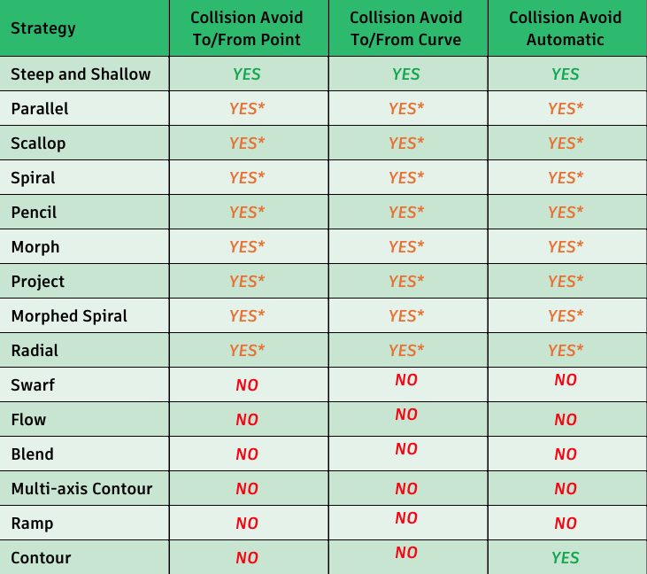
Here’s a handy chart summarizing the collision avoidance options for 3D finishing toolpaths available in Fusion 360.

Browse advanced tool axis options
In addition to primary tool axis settings and collision avoidance, Fusion 360 offers a suite of advanced options to provide deeper levels of 5-axis control, including:
Smoothing Angle and Smoothing Distance
These two tool axis smoothing options can be combined to improve machine motion.
Smoothing Angle
This is the maximum angle the tool axis is allowed to deviate away from the Primary Mode while moving along the smoothing distance. The Smoothing Angle takes effect when there is a sudden angular change between two positions. This sudden deceleration and acceleration can cause the tool to dwell on the part, resulting in an undesirable surface finish. The greater the smoothing angle, the more the tool axis is allowed to deviate away from the Primary tool axis mode.
Smoothing Distance
This is the maximum linear distance over which sudden 5-axis motion is smoothed out. Consider a 5-axis toolpath that is sweeping around an external corner on a part. Without smoothing, the tool axis could swing suddenly and erratically, causing jerky motion as one or more the axes cannot move fast enough to cope with such a sudden change. By using a Smoothing Distance, the tool axis starts changing well before the external corner is reached and then gradually transitions to the next tool axis orientation over a longer distance. This smooths out the motion, improves surface finish, and shortens cycle time as the machine doesn’t have to keep stopping and starting.
Override tilt angle
When activated, this option limits the amount of tool axis tilting that will be applied such that it never exceeds a user defined Preferred Angle. The angle is calculated relative to the reference Z-axis used in the toolpath (generally the setup’s z-axis).
Tool axis limits
This option ensures toolpaths are calculated with tool axis motion that stays within the travel limits of your CNC machine. Minimum and maximum tool axis limits can be defined (relative to a Reference Z-axis). If a toolpath reaches these limits, the programmer has choices whether to delete any additional toolpath segments or lock the tool axis at the defined limit but allow the toolpath to continue machining.
Fusion 360: One solution for 5-axis machining
So far, we’ve considered the separate elements that go into a 5-axis toolpath – but the magic really happens when we combine them together.
It’s important to note that Fusion 360 applies tool axis settings in a logical, prioritized order. This begins with the Primary tool axis which defines the initial 5-axis motion we’re aiming to achieve (remember the options were vertical, to/from a point/curve, and lead/lean). If we also activate “Override Tilt Angle” the preferred angle will be used to adjust the primary tool axis. If we then activate Collision Avoidance and define appropriate values, these will override the preferred angle that we defined previously.
Finally, if we enter tool axis limits, these will further constrain the 5-axis motion. The point here is that there are multiple layers of tool axis control; and each affects the previous setting. This provides incredible levels of control and flexibility to allow you to achieve the desired machine motion for your part.
See Fusion 360 5-axis machining tools in action
Watch the below tutorial to see these 5-axis machining options in action. Here, we walk you through the various tool axis options and explain how they can be combined to achieve different solutions.
Ready to try 5-axis machining with Fusion 360? In addition to accessing 30-day free trial of Fusion 360, you can also start a 7-day free trial of the Fusion 360 Machining Extension. Try the Fusion 360 Machining Extension for free today:

