& Construction

Integrated BIM tools, including Revit, AutoCAD, and Civil 3D
& Manufacturing

Professional CAD/CAM tools built on Inventor and AutoCAD
14 min read

V.2.014569
NOTICE: Important OS support information after March 2023
After the March 2023 product update, Fusion 360 will no longer fully support the OS versions listed below:
In order for us to continue developing Fusion 360 for the latest and greatest, we must stay current and end support for older OS versions. We recognize that this change may take you some time to adjust to. That’s why we are letting you know now, so you have plenty of time to update your OS to the latest version. We will continue to remind you here as well as in-product as we get closer to the March 2023 product update.
Live with the Experts: What’s new in Fusion 360 October 2022
Join us for this exclusive 60-minute live event with Fusion 360 experts. We’ll cover the latest and greatest features from all workspaces, showcase live demonstrations and open the floor for plenty of LIVE Q&A.
We have 2 sessions, running on Thursday, October 27th 2022, for you to choose from, both identical in content, just at different times. Click the links below to sign up. Looking forward to seeing you there!
10am UK | 11am CEST | 2.30pm IST
V.2.0.14567
Performance boost to commonly used commands
This October we focused on improving the performance of commonly used commands across Fusion 360. This included:
Performance issue related to NVIDIA drivers
We’ve heard that many of you reported performance issues in Fusion 360, and upon investigating, we discovered that these issues may be related to Nvidia and GSYNC settings in the Nvidia drivers. For Fusion users who are running on the Windows systems with NVIDIA cards, we highly recommend upgrading to the latest driver 517.40. This can address a performance slowness caused by enabling G-SYNC setting from the NVIDIA Control Panel.
Here are the drivers:
Geforce: https://www.nvidia.com/Download/driverResults.aspx/193235/en-us/
Quadro: https://www.nvidia.com/Download/driverResults.aspx/193171/en-us/
Applying Physical Materials now gives you the choice to Keep or Remove existing materials
Changing Physical Materials just got simpler. To align with the Appearance command, changing Physical materials now provides you with the choice to either keep or remove existing materials, giving you a more streamlined and uniform experience.
Inferencing for Electronics

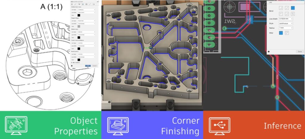
We have been working hard to integrate more and more of the Fusion 360 Design sketch capabilities into the Electronics workspace. These small productivity boosters contribute towards a frictionless design workflow for you. Before today in Fusion 360 Electronics, it could be cumbersome and time-consuming to understand precisely where your sketched lines are connected. In this release, we introduce Inferencing, A.K.A. ‘object snapping.’ As you draw, it’s now possible to automatically snap to endpoints or midpoints, draw tangent lines, and so much more. Inferencing makes drawing components, footprints, and complex board outlines easier and faster. Go to your electronic preferences to enable it.
Layers dialog is now a dockable panel

You will be saving time and mouse clicks with this enhanced feature. Circuit boards have multiple layers such as silkscreen, copper, component origin, and many more. With this new dockable panel, you can minimize or dock the layers view, providing you with more canvas space to accomplish your design. Remember that with the Display Panel, you can define layer sets, so switching between a top, bottom, or silkscreen view of the PCB can be done with even fewer clicks.
New Pattern/Arrange Command
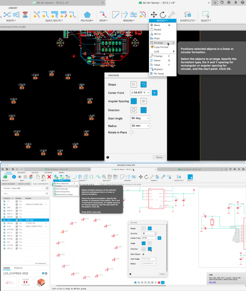
Ever spent too much time manually arranging many LEDs in a particular way on your Schematic or PCB? The Pattern and Arrange commands accomplish just this instantly. The recently enhanced Pattern command enables you to generate duplicates of objects in a customizable rectangular or circular pattern. In contrast, the new Arrange command translates existing objects into a customizable arrangement. These productivity boosters help your Schematic keep organized, and your PCB be designed quicker. These commands aren’t limited to components either; they can also be used for text or silkscreen objects.
Learn more about Patterns and Arrangements.
Flat Caps option now available in Route tool

Many of you will remember that in the last update, we introduced the option of flat caps – the ability to change the trace geometry on your PCB. When two traces of different widths overlap in a ‘T connection’, unwanted trace artifacts may appear, negatively affecting PCB performance at high frequencies.
Now, by including the Flat Cap option in the Route Manual dialog box, you can switch trace types on the fly without leaving the active command, quickly preserving your PCB’s performance.
New “Insert Electronics Design” Command

We’re sure you have used the phrase more than once “No need to reinvent the wheel.” Well, that is the case with this new update. Why not reuse proven technology for your future designs? Save design time by using the new Insert Electronic Design command. Re-purpose existing Schematic and PCBs. You no longer have to re-layout that amplifier or Wi-Fi module configuration you have used in many of your products. After inserting the schematic, the associated PCB will appear in the PCB workspace, ready to be placed.
Library Editor Pad Array

Make Via Command Interactive (preview during placement & add obstacle-awareness)

Vias are common design tools for ‘stitching’ and ‘shielding’ PCBs. Via stitching on the PCB is where many vias connect copper areas on different layers together. Via shielding is where one or two rows of vias connect copper pour together at the perimeter of some tracks or the copper pour areas.
You will no longer have to spend time manually making space when placing vias. Before today, when transitioning between layers, the selected Via would comply with the ‘Push & Shove‘ or Walk Around violator modes while routing. For this update, placing individual vias will now respond to the corresponding violate mode, so traces or adjacent vias will attempt to make space with the ‘Push & Shove’ active.
Show device name in Design Manager and Inspector

We continue expanding the capabilities of the panels, this time by providing you with more information on your design without having the search for it. Traditionally, getting the device name of a component on your schematic or board requires navigating to the component properties; this translates to too many clicks. Having the device name appear on the Inspector, and Device manager will let you know if the device you intend to use is the correct one at a glance.
Performance and Stability Improvements
New Commercial Solver
Throughout 2022, we have been working on hard on our Experimental Generative Solvers and Features Preview in the Generative Design for Structural Components study. We are now ready to graduate our solver portion of that preview to production. With this update, the primary solver technology will be new, but this doesn’t change the workflow, or anything related to how you use Generative Design. You should expect to see your solutions generate noticeably faster (in some cases twice as fast), and you should notice better quality shapes, overall, a huge step forward that we are beyond excited about. If by some chance you do run into an issue with this new solver, please let us know right away by dropping us an email at generativedesignhelp@autodesk.com.
Note: The legacy solver can still be enabled temporarily by turning on the Experimental Generative Solvers and Features preview and enabling Alternative Outcomes in the Study Settings Dialog but will be retired in an upcoming release.

Learn how to specify the study settings.
Improved Simulation Cloud Solve Performance
We have made improvements in the simulation cloud solve pipeline which will now improve the cloud solve performance by several minutes. The average solve time for very simple Linear Static jobs was previously around 5-6 minutes, which will now go down to approximately 3-4 minutes. This is an active investment from our teams, and we will continue to bring improvements in the time to result for cloud solve in the future releases of Fusion 360.
New Ability to download NAS file for Structural and Event SIM studies
We have added the ability to download the nas file for the Structural and Event SIM studies you run on the cloud. This nas file can be imported in other FEA products for advanced analysis. You will have to follow the steps below to get the nas file from your cloud solve.
Improved Simulation Materials Usability
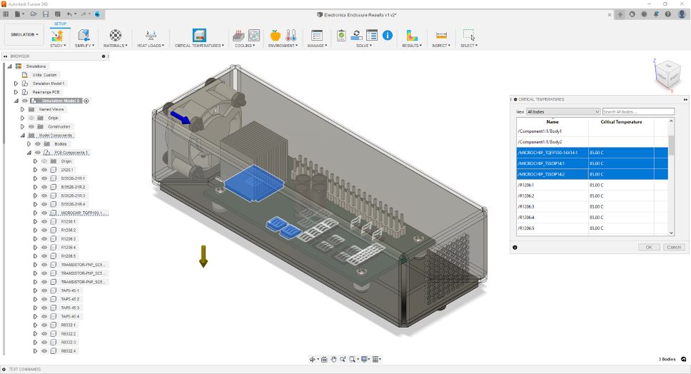
To improve usability of the Materials dialog, we have implemented cross-highlighting with the components in-canvass and the browser tree. Selecting a component in-canvass or a body in the Model Components in the browser will now highlight the selected component in the Materials table and will automatically scroll to that line item. This will also work for multiple selections.

Improved Electronics Cooling Setup
Ambient Temperature has been moved from the Study Settings dialog to the Ribbon and is now available as a separate command as well as has a browser node in the Load Case. You can also copy paste Ambient Temperature value across Electronics Cooling Studies.
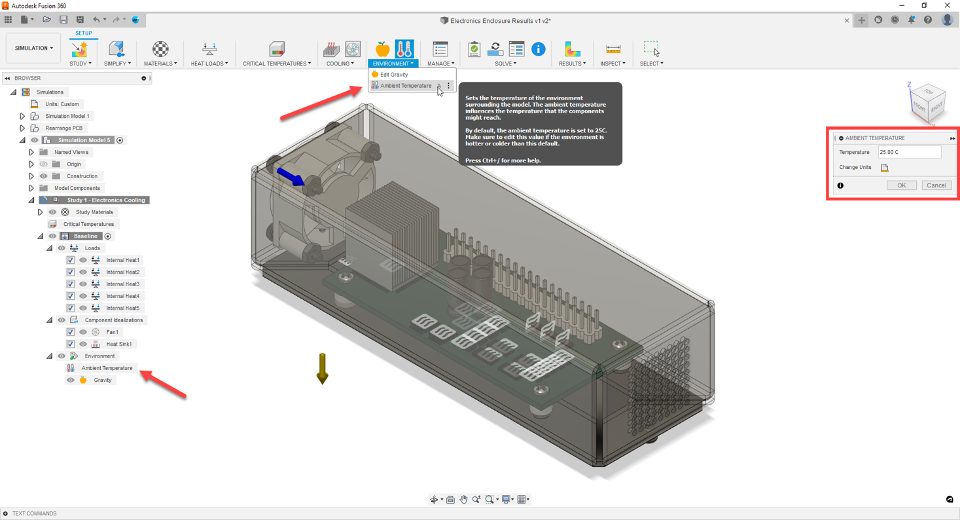
To Improve usability and have distinct categorization of the inputs, the Load Case inputs are now separated into three categories in the Study browser, viz. Loads (Internal Heat), Component Idealization (Fans and Heat Sinks) and Environment (Gravity and Ambient Temperature).
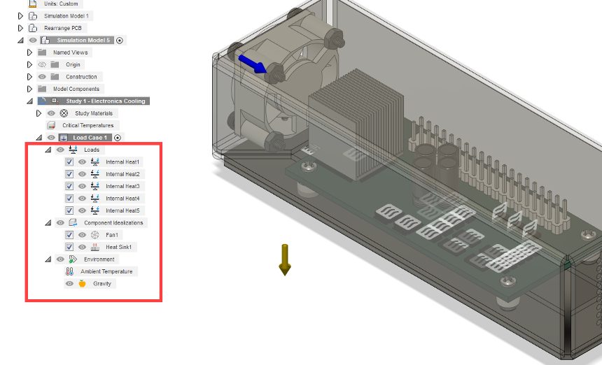
To improve usability of the Critical Temperatures dialog, we have implemented cross-highlighting with the components in-canvass and the browser tree. Selecting a component in-canvass or a body in the Model Components in the browser will now highlight the selected component in the Critical Temperatures table and will automatically scroll to that line item. This will also work for multiple selections.
Improved Object Properties
Within the drawing workspace you can now change line type, width, and color OR bring in document settings from a template or other drawing. Additionally, you are now able to toggle on or off dimension gaps to meet your requirements. This gives you significantly more control when creating standardized drawings. In addition, color controls have been added to sketching and text creation tools.
Updated Attributes
The “Description” attribute from the model is now available in title blocks, which rounds out additional attributes that we released in May.
New Enhanced Flow Subtractive Toolpath

Using the enhanced flow toolpath in Public Preview you will now be able to obtain a better toolpath quality and surface finish. This toolpath supports step-over control rather than number of passes and is calculated based on underlying surfaces. Please note that this is not a replacement for existing Flow.
New Ability to 3axis Undercut Machine within the Blend Tool

You now can 3axis undercut machine using the blend tool in Public Preview. Note that this tool currently only supports lollipop tools for undercut machining.

Improved Machine Builder V2

Define complex multi-axis machine types using the new Machine Builder Configuration tools. With this update Machine Builder V2 brings you a better user experience giving you machine image customization and the ability to accomplish more complicated machine kinematics. This means kinematics chains are now split to enable single kinematics chains to use multiple control types, and static parts are now definable in the kinematics tree.
New Subtractive Corner Finishing Update to Corner Strategy
(Extension Preview)

Having trouble machining those pesky corners? Look no further, now within the Machining extension you will be able to preview Corner Strategy to help you target areas such as corners, internal fillets, and small pockets that have been unreachable by tools used in previous operations. Within this extension preview you can reference tool support for more accurate rest machining, use shorter tools with the help of 5axis and collision avoidance, and achieve an overall superior quality tool path and better-quality surface finishes.

Improved Move Components Command
Move components command within an additive setup now allows users to choose between “Machine XYZ” and “Component XYZ” as the Coordinate system input. In the past there was no option to select a coordinate system for the move command and all move operations were based on the “Component XYZ”. After a user made a rotation around X or Y axes, it was very difficult to translate the component in the global XYZ axis without this new addition.
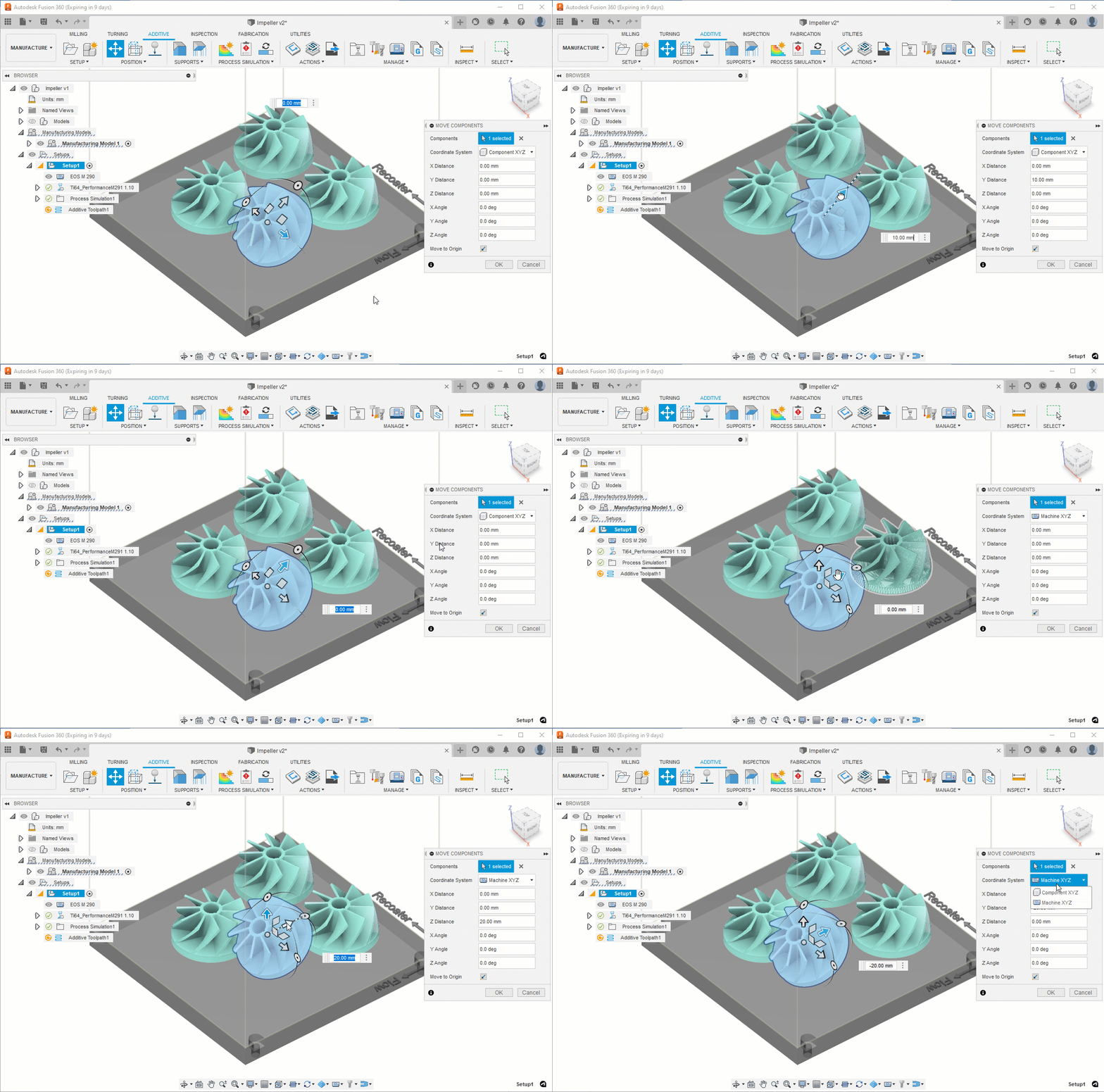
Learn how to move or rotate a component in a build volume.
Better visibility for Support Structures
With this release Additive Support Structures are always visible regardless of camera angle. In the past if a support structure was very thin (single-laser hatching) it would not be visible when looking at it from the bottom view. They adhere to the selection/highlight color scheme of Fusion. Support structures are visible and adhere to Slice analysis.
Learn how to add support structures for additive manufacturing.
Updated Product Model Information Interaction
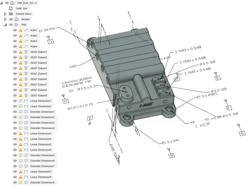
Now within Inspection you will be able to import and view PMI using Inventor, STEP, and NX files, this will help you leverage your existing 3D model data and optimize your workflow.

Looking for the latest post processors and machines updates? This October we released a ton of new updates and improvements to many of the open-source Post Processors and Machines we offer for free. Within this release you will see new beta post processors for many Hyundia WIA series machines, as well as improvements to milling post processors, mill-turn Post processors, and waterjet/laser/plasma post processors. Additionally, we added new machines to our machine library and improved functionality around the Autodesk CAM Post Processor engine.
To learn more check out the forum post here.
To learn more about other improvements that went into this update, our extended list of fixes to issues reported by you, as well as known issues, check out the related Known Issues, Improvements and Fixes forum thread below.
See improvements and fixes for this update
By clicking subscribe, I agree to receive the Fusion newsletter and acknowledge the Autodesk Privacy Statement.
Success!
May we collect and use your data?
Learn more about the Third Party Services we use and our Privacy Statement.May we collect and use your data to tailor your experience?
Explore the benefits of a customized experience by managing your privacy settings for this site or visit our Privacy Statement to learn more about your options.