& Construction

Integrated BIM tools, including Revit, AutoCAD, and Civil 3D
& Manufacturing

Professional CAD/CAM tools built on Inventor and AutoCAD
21 min read
This “What’s New” post has its own table of contents because of how much we’ve packed into this update, specifically in Simulation and HSM CAM. This is also the last update before Autodesk University 2016, so you know, go big or go home. If you’re in a pinch for time, check the various topics that matter to you the most. Let’s do this.
Jump to a topic:
You now have 2 subscription options: The Standard subscription tier and the new Ultimate subscription tier. The Ultimate option includes everything that you love about Fusion 360, and packs in additional advanced Simulation and HSM functionality. Yes, it costs more than the Standard tier, but what Ultimate gives you is still way more affordable than the status quo, and is great bang for your buck. Check out the extensive comparison chart on our website and decide which tier best suits your needs.
And yes, if you’re on our free student, startup, or hobbyist subscription, you’re automatically getting the Ultimate tier. For free. Because sharing is caring.
Need some more questions answered? Check out our FAQs.
We’ve come a long way since the days when we had to rely on trial-and-error to determine whether the products we design will perform amicably or spontaneously combust into a fiery ball of death. Software can now help us answer questions during the design process, questions like, “Is this thing going to break? Is it going to fit together? Can I make it lighter?” Simulation shows you forces and loads and how they interact with your design, saving you precious time, materials, and headaches of experiencing design faults the hard way. We think Simulation is a key part of the design process, and that if you’re designing something, you should be simulating it so that you can optimize your design, before it gets in the hands of all your customers.
There are 3 major areas where we made updates to the Simulation workspace. A solver overhaul, new usability enhancements throughout the workspace, and advanced simulation capabilities available for Ultimate subscription users.
Put your engineering hat on. It’s about to get nerdy.
Autodesk Nastran is now the part of Fusion 360! This allows us to expand on the current study types and provide much more advanced capabilities mentioned below. It’s nice to be part of a family where we can share toys with each other, especially from our older brothers and sisters.

Note that when you run a local solve study for the first time, you’ll see a quick prompt, letting you know that Fusion 360 will install the new Nastran Solver. After this is done, you’ll have the new solver and will not see this dialog again (unless you uninstall and reinstall Fusion 360 that is).
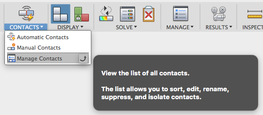
Previously when you automatically generated contacts for your assembly components in the Simulation workspace, there wasn’t a good way to manage all your contacts. If your assembly was very complex, going through the contact type for each part could become very a long and arduous process.
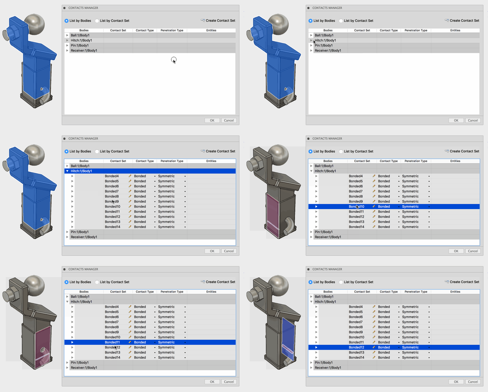
Now under the Contact drop-down menu, we’ve added a Manage Contacts tool where you’ll find all your contacts in a neatly organized list, with contact type, penetration type, and some other info you can edit.
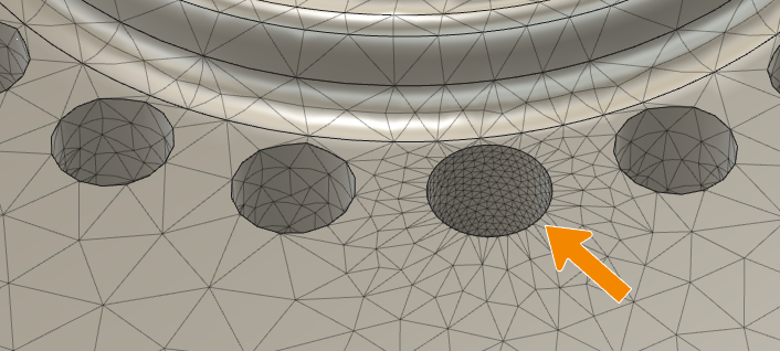
Now when you generate a mesh of your design, you can fine tune the density of that mesh in specific areas so that you can maintain a certain level of detail when needed.
Under the Manage drop-down menu, there is a new Local Mesh Control tool. Select the face, edge, or body you want to refine, then use the slider to change the value, and get a quick preview of the new mesh density, represented by the green dots. Once you’re happy with it, click ok and re-generate the mesh. Now you’ll get a more refined mesh around that area you’ve selected.

Here’s where it gets really fun. Now when you need to solve a study for a design that requires to be bolted onto something else, you can drop some bolts right onto the part with our new Constraint > Bolt Connector tool.
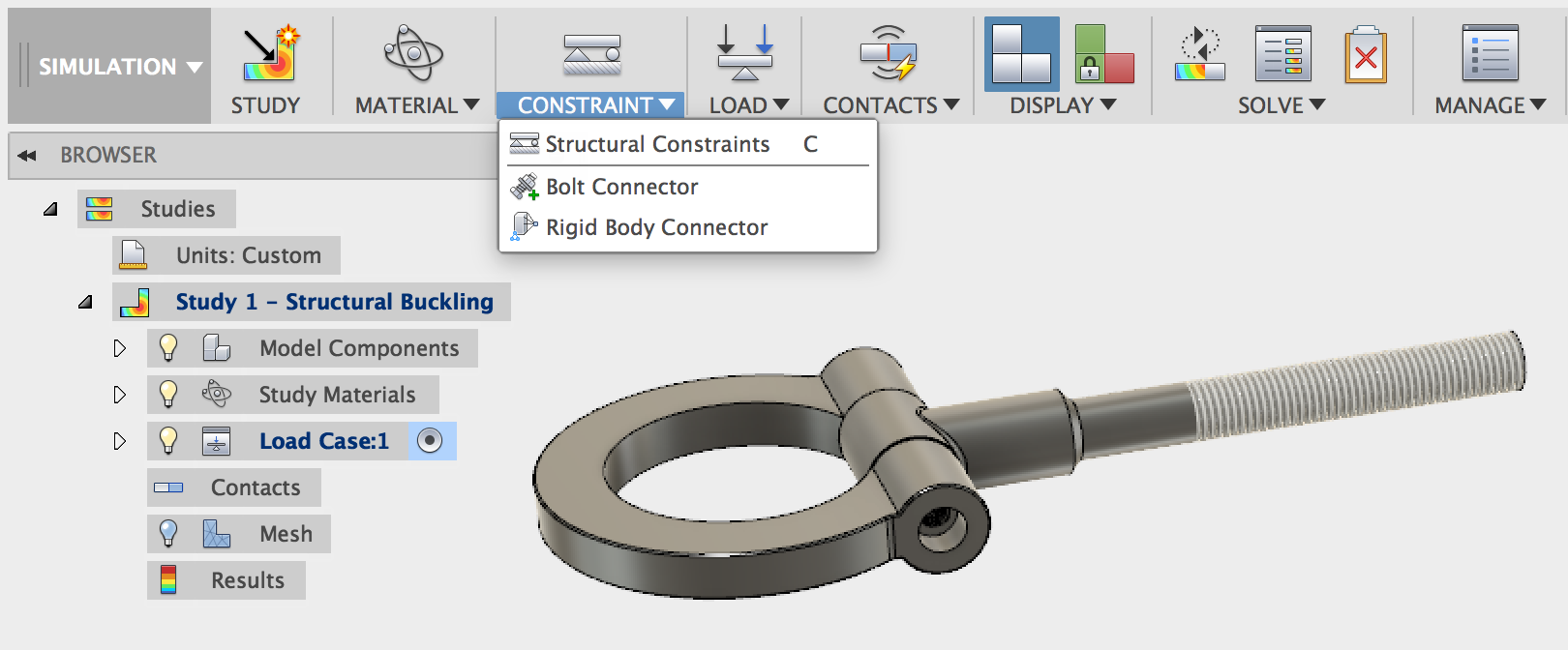
Once the tool is active, select the edge where the bolt is going to contact, then where the nut is going to be, and then go through the dialog and set the type of preload, preload value, and many other options. You can also set the Bolt Subtype to a threaded version if your design has threaded bolts. Aw snap!
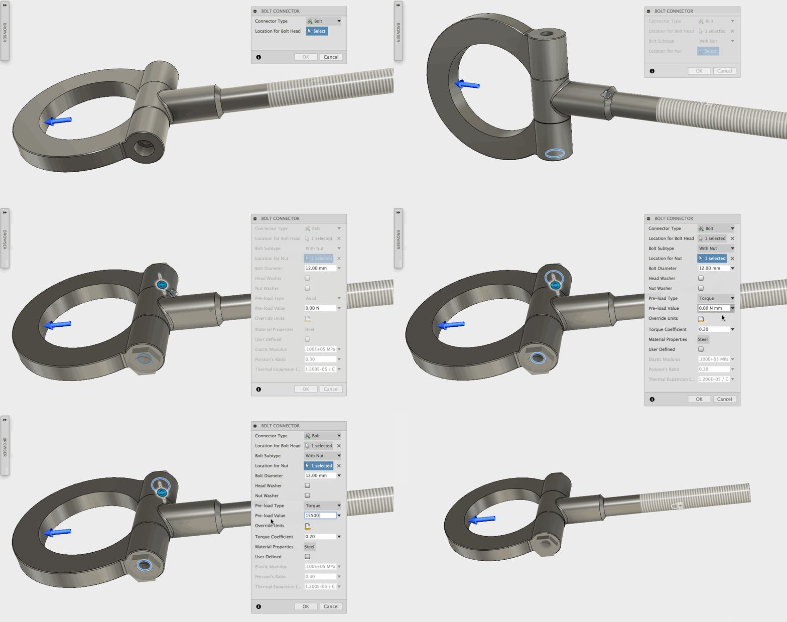
You can see in this example where 3 of the 4 holes are bolted down to the plate, and the last one was left unbolted. The results show that unbolted area would be affected by the upward force applied to the top hole. Once the 4th hole is bolted down, the results got a lot more accurate in terms of where the hinge would experience potential failure. Neat!

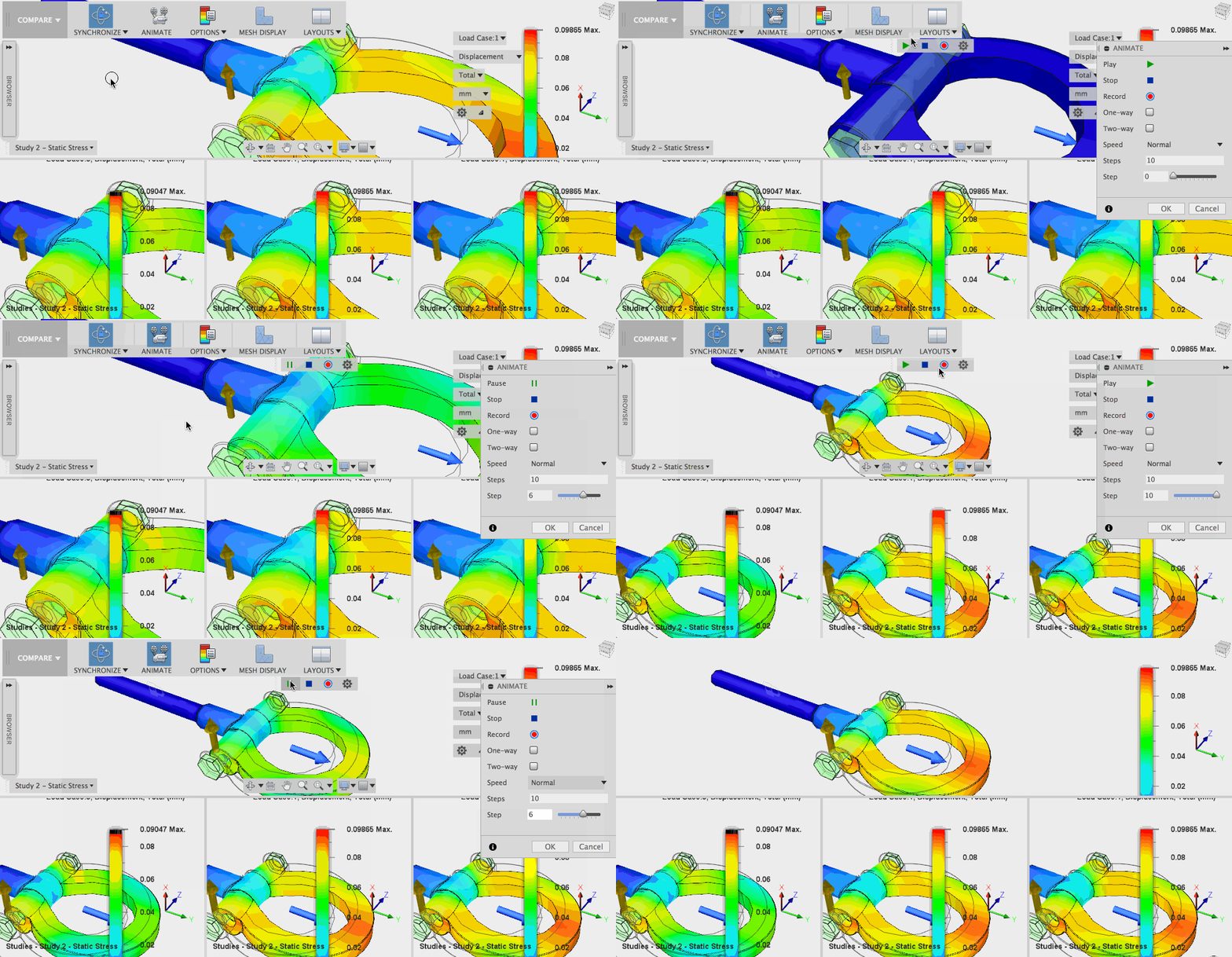
Previously if you had a number of different studies and wanted Fusion 360 to solve for them, you were only able to see the results one at a time. Now you compare results generated from multiple load cases in a workspace conveniently called Compare (why complicate things, right?)
Now within each study, you can also have multiple load cases. This is especially useful when you’re using shape optimization, which I’ll get into later.
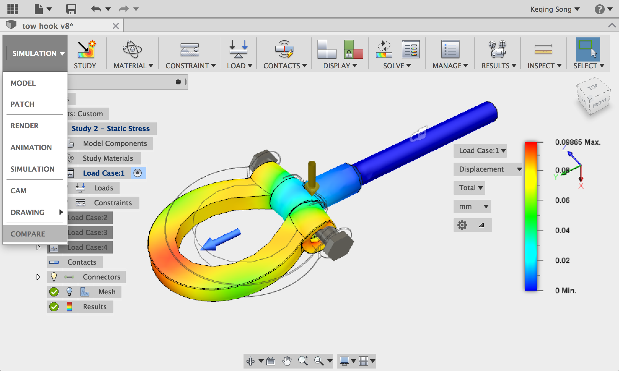
Note that the Compare workspace only appears after you’ve solved your studies and have gotten the results. Here are a couple of tips to start comparing your results:
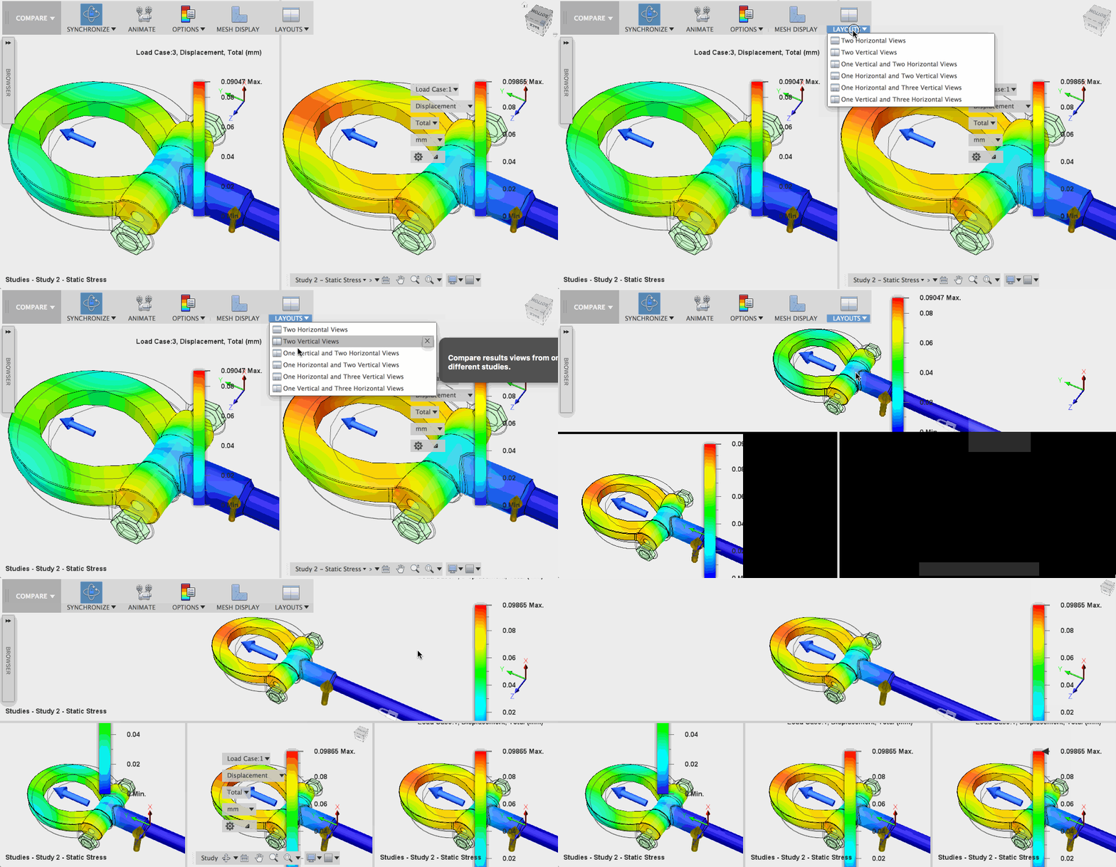
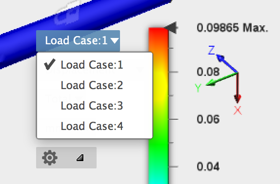
2. Click on each frame to activate it. Within the Load Case drop-down option, change the load to show other loads so you can do a legitimate side-by-side comparison of radness.
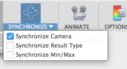
3. You can un-sync your views by going to the Synchronize drop-down menu and un-checking Synchronize Camera.You can also decide whether you want to sync/un-sync by Results Type or Min/Max.
4. The Compare workspace will work with the same study with different result types, same study with multi-load cases, or different studies all together. A visual comparison will also included in the reports you generate. *MIC DROP*.
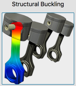
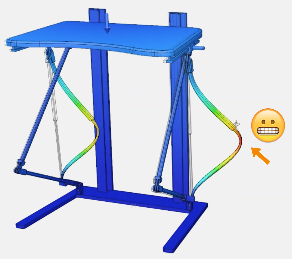
Wouldn’t it be great to know how many of your crazy friends your table could support before its legs gave out and the whole thing ended up on YouTube as a fail video? Well now you can! (as in try structural buckling in the Simulation workspace and please don’t try it at home).
Just like any other study, set your constraints, gravity direction, loads, and run the study. Once you have everything set up, the results will show you exactly where the design is prone to buckle, demonstrated by this standing desk (designed by Noorul Islam) with a certain load applied on the table top.
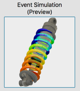
We’ve mentioned Event Simulation before, and now it’s available in the Ultimate subscription as preview functionality for you Ultimate subscribers to play with.
This study allows you to simulate realistic scenarios such as drop tests, snap fits, assembly forces and loads created during use. For instance, using event simulation and by setting up all the necessary study requirements such as distance, material, contacts, and constraints, I can clearly see what part of this buckle mechanism is undergoing the most amount of stress and displacement.

You can control the in-and-out motion with a simple slider tool once you have your results to see it in action.
Oh, but it gets even better. Since designs are meshed before each study, event simulation also has the ability to remove material to show breakage in real-time when a part has exceeded a certain amount of failure criteria. The example below shows it off pretty well. We’d like to call it “Judo Chop”.
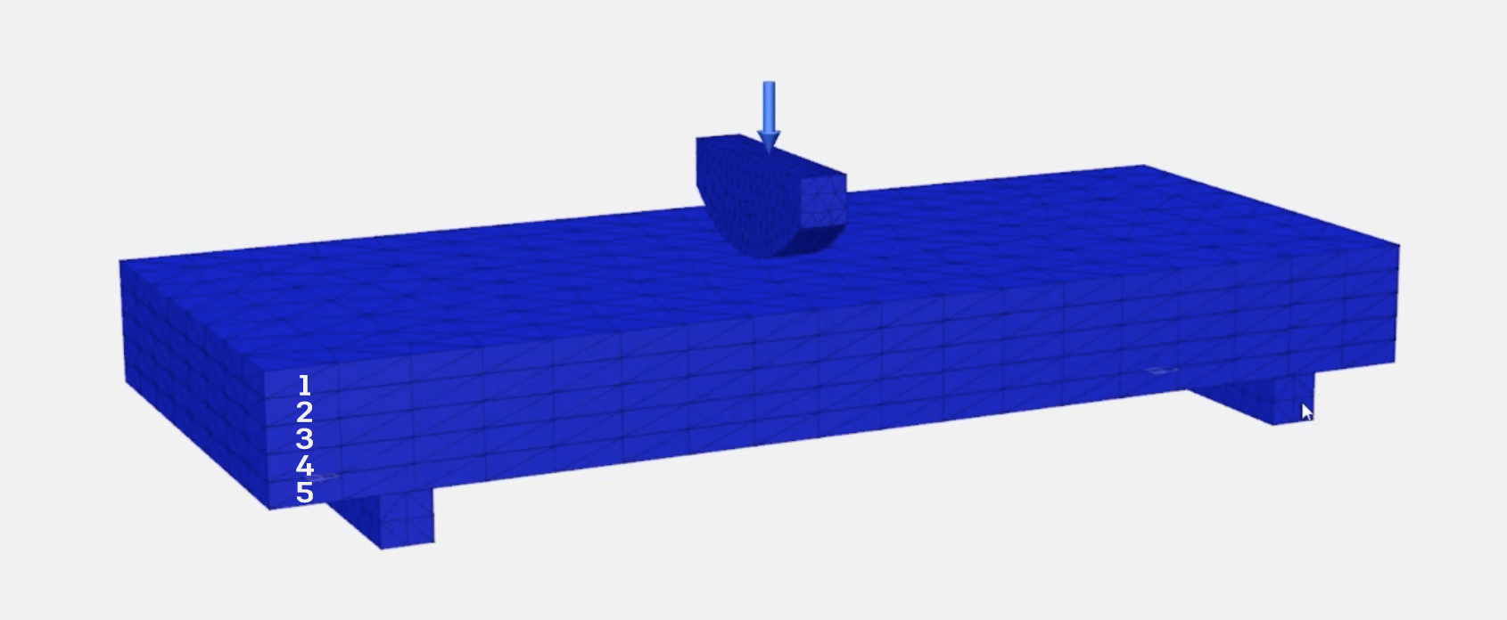
Behold: we have 5 boards on top of each other, laying on 2 constrained legs, and a part on top of the first board with rigid projectile load going down, and obviously way too much for the boards to handle. Let’s see what happens when we run the simulation.
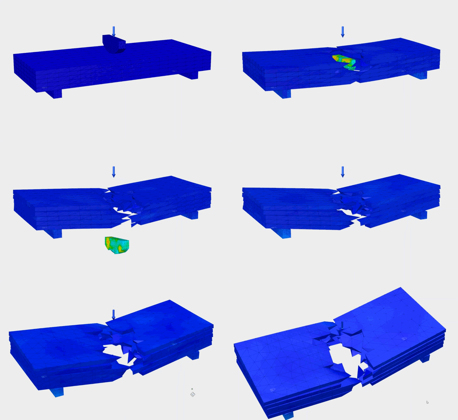
Let’s just watch that a couple of times. Austin Powers would be proud.
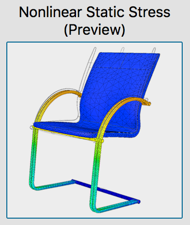
The best way to describe what a nonlinear static study allows you solve for, starts with understanding what linear static stress is first. Linear means proportional, where the stress and strain curve is a straight line.
Nonlinear static stress happens when materials enters a zone that’s beyond its yield strength, in which case, it is no longer linear. As described in this Quora answer by a structural engineer, you may see your part showing permanent deformation, cracking, or energy dissipation (heat) when it is in this this nonlinear zone.
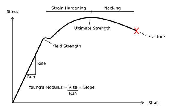
Now in Fusion 360, you can solve for these scenarios and see how your design behaves when it goes beyond its materials’ yield strengths.
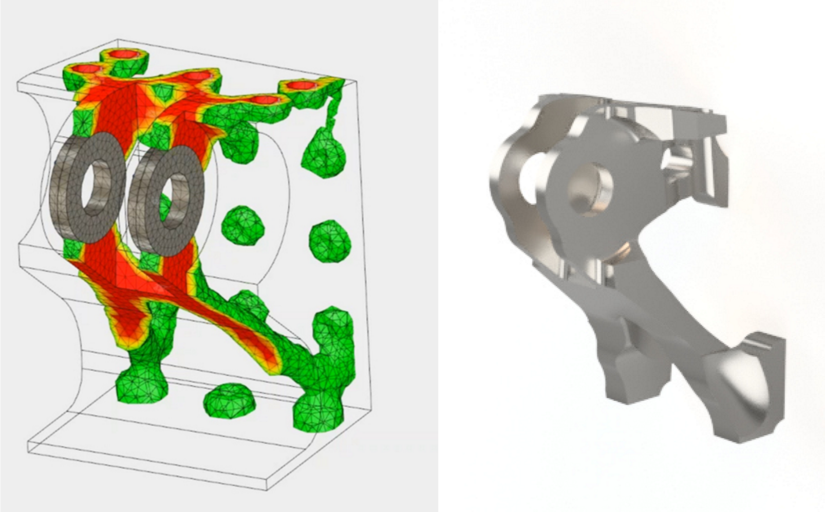
Also available as a tech preview is Shape Optimization, where given a set of loads, constraints, and mass targets, you can solve for results that help you optimize the shape of the design by “lightweighting”. The results can help you understand the areas you can remove material, without affecting structural integrity. Colin Chapman said this best: “Simplify, then add lightness”.

This image shows the original part (left) and the optimized solve result (right). Red areas indicate where you should not remove material, whereas green means you are okay to remove that material. Oh yeah, remember the Mesh workspace? Yup. That’s where you can take your simulation mesh bodies and lightweight them with all the mesh tools available. It’s all coming together!
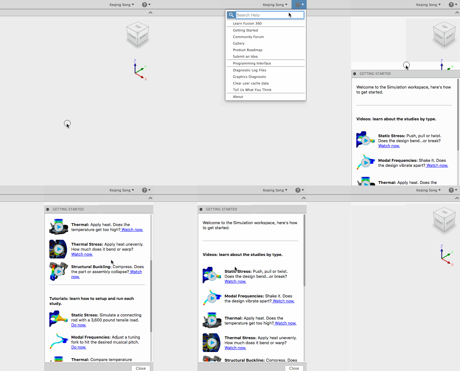
For those of you who are not familiar with simulation and feel a bit overwhelmed with all this simulation mumbo-jumbo, don’t fret, we’ve thought of you. When you get into the workspace for the first time, you’ll be greeted with a Getting Started panel that has simulation specific videos, as well as step-by-step tutorials. Get familiar of what each study type means, how to set them up, and how to make sense of the results. The Getting Started Panel can be found in the Help menu, so you can get it back at any time.
In addition to these great new features, let’s not forget about bug fixes. Here are some notable ones.
Under the Samples > CAM Samples > Workholding folder in the data panel, we’ve added a number of new fixtures that you can use for the CAM setups. We will periodically add new fixtures in there as they become available, so keep an eye out for them!

We’ve added 3 new tool types to the tool library:

Al Whatmough posted a nice little Instagram teaser video a couple weeks back, showing how you can customize the thread count on your Thread Mill by simply scrolling your middle mouse wheel. Neat!
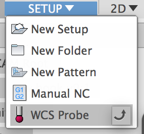
No, this is not about alien abductions or the Ford Probe. Under the Setup drop-down menu you’ll see a new tool called WCS Probe. This allows you to make sure that your stock is positioned correctly so that you don’t run into problems when you’re physically cutting the part.
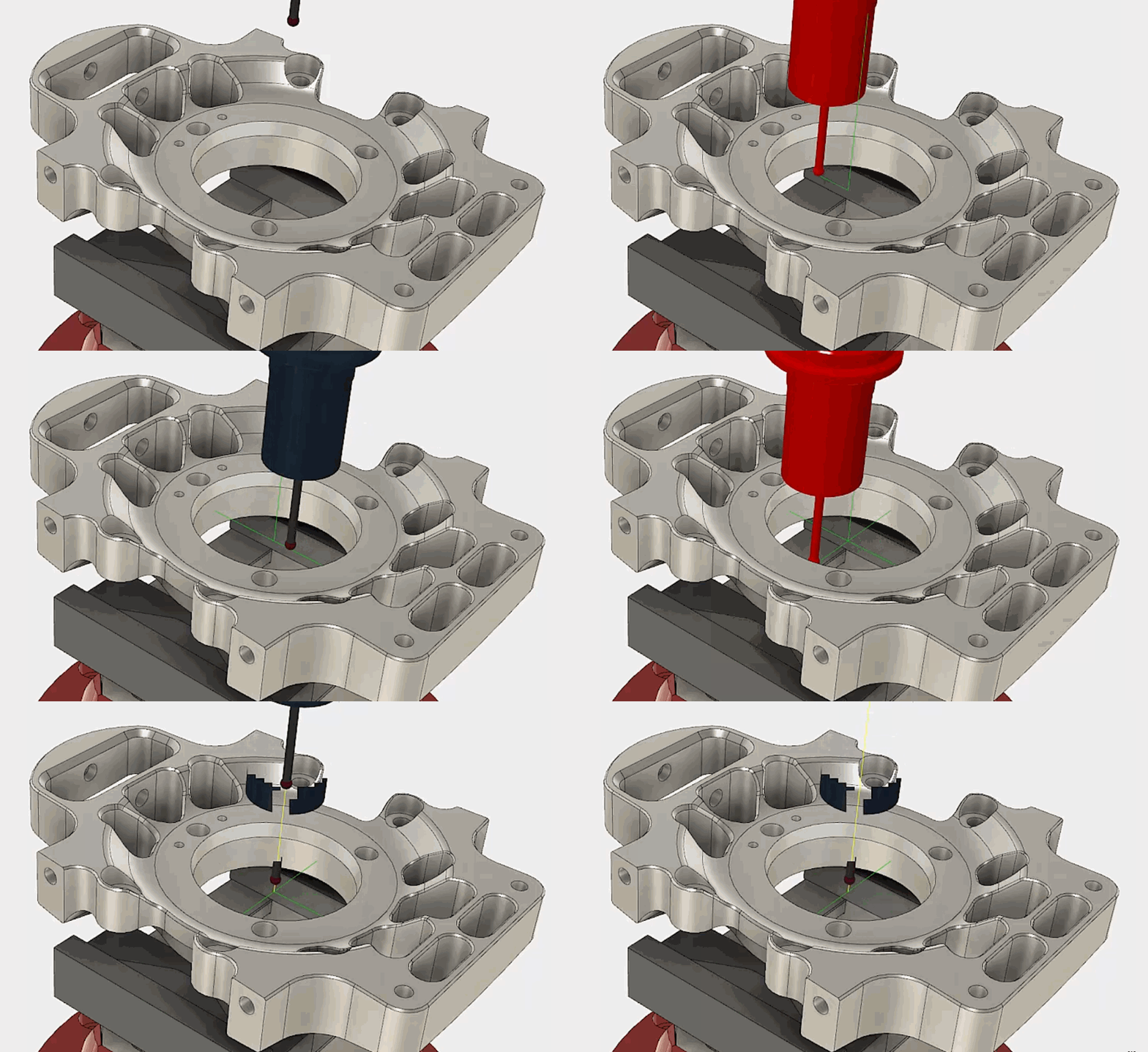
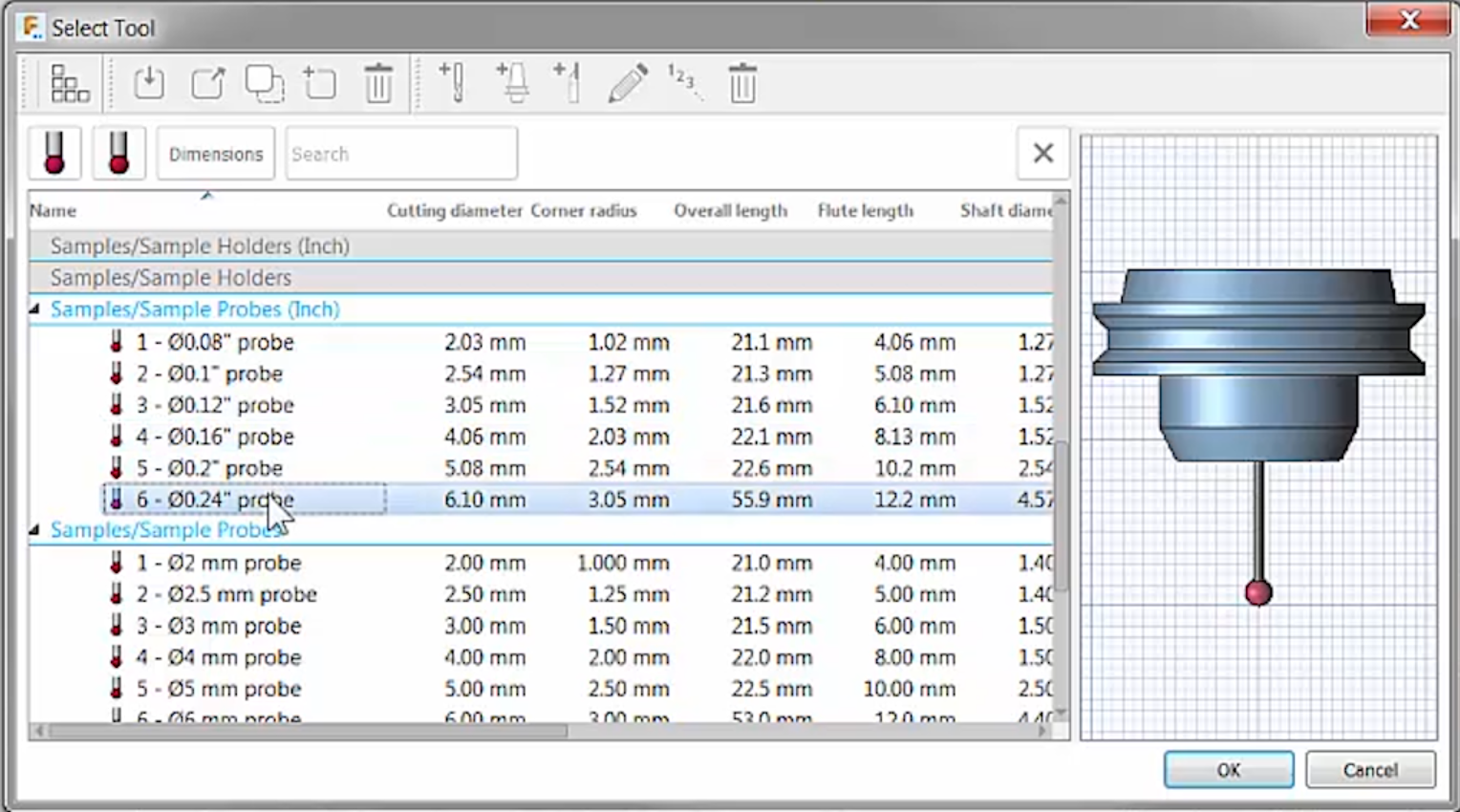
There are a number of different probes you can choose from in the tool library, so pick the one that best suits you and probe away! Here’s a 10 minute lesson on how to get started.
4-axis wrapping lets you create a 2D Contour toolpath and wrap it on a cylindrical face. You also get indexing as well, so that you don’t have to recreate the same toolpaths over and over for a pattern on multiple sections of the cylinder.
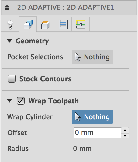
With Wrap Toolpath checked in the Geometry tab of 2D Adaptive, you can select the face you want the toolpath to wrap, set your heights, and voila, you just created your wrapped toolpath.
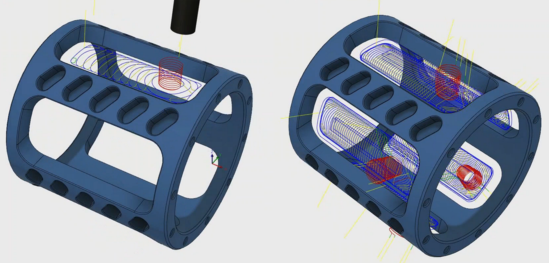
Left shows the toolpath wrapped, whereas the right shows a similar but slightly modified toolpath indexed and patterned throughout the cylindrical part, using the Setup > New Pattern tool.
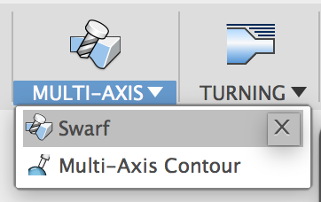
Previously when you wanted to cut a chamfer, you would need to use something like a ball end mill and make a number of passes to get the result you’re looking for. Now with Swarf, you can use the side of the tool to create a toolpath that can easily cut a chamfer, in quicker time, and with a much better surface finish. Here are a couple more lessons to help you get going.
5-Axis Swarf Tutorial Part 1 | 5-Axis Swarf Tutorial Part 2
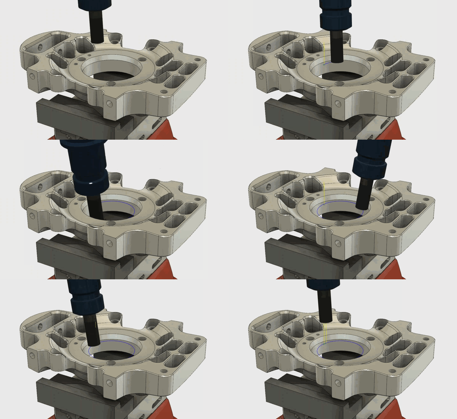
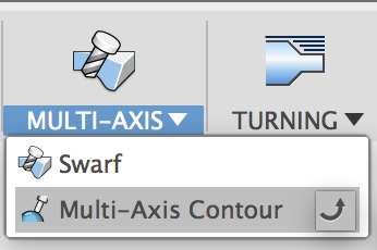
Now you can create toolpaths that use the tip of a tool to cut normal to the surface of a curved part. Don’t want the tool to be normal all the time? No problem, as you can also define a lead/lag and tilt angle when needed, to precisely control the contact angle of the tool.
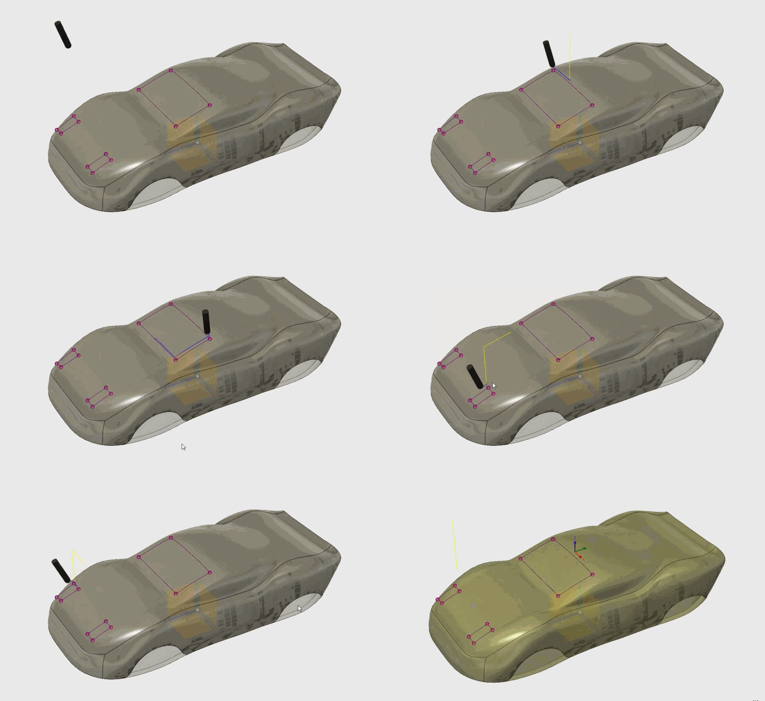
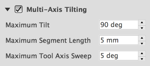
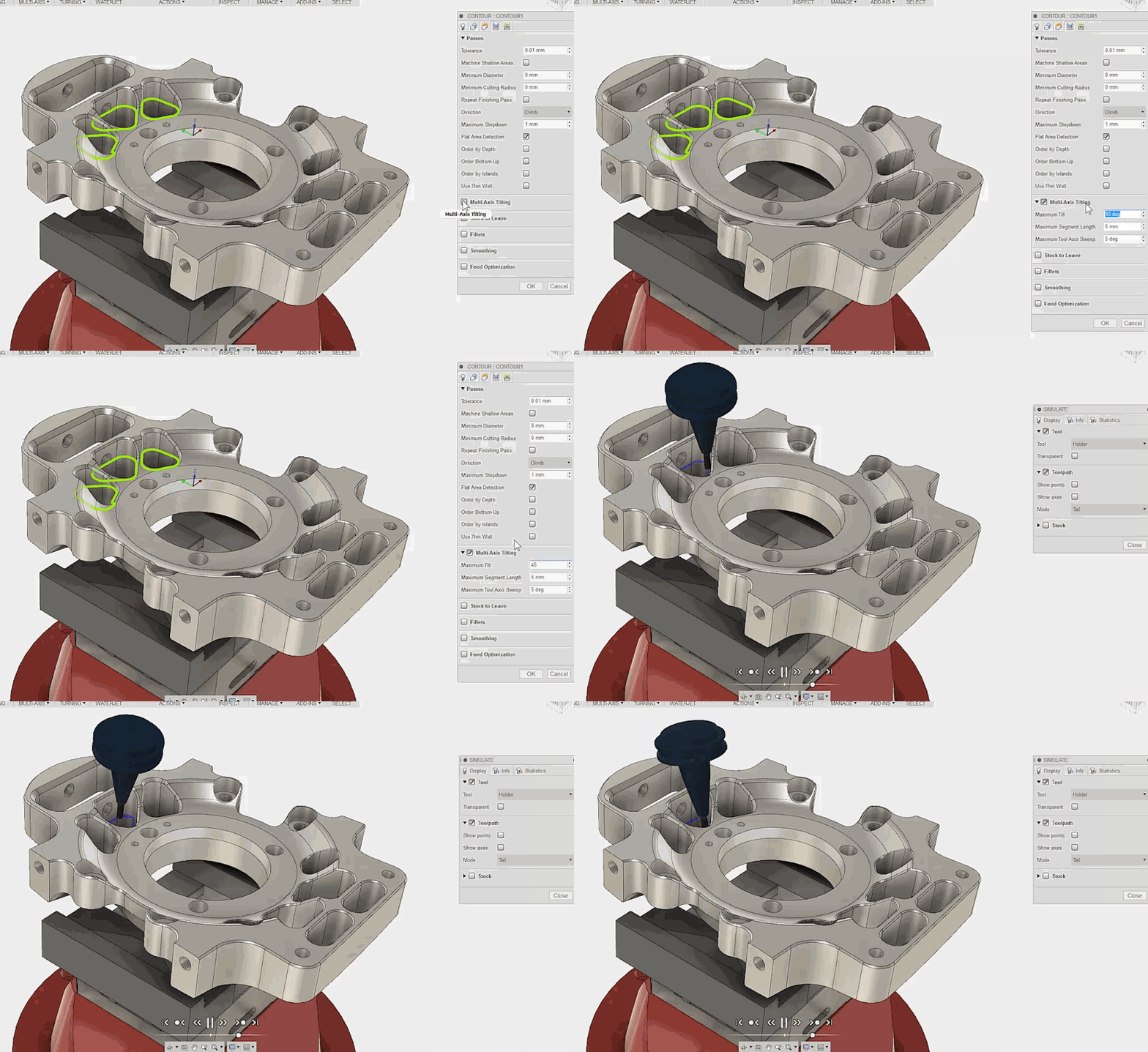
Speaking of tilting, you can now tilt your tool for 3D Contour strategies as well. Think of it as an expansion of the shaft holder detection functionality. Under the Passes tab of the 3D Contour dialog, check Multi-Axis Tilting and set the angle for max tilt, length for max segment, and angle for max tool axis sweep. Note that it can’t reach an undercut that it couldn’t reach before.
Here are the notable HSM fixes that made it for this update.
Quench your thirst for more CAM knowledge; our resident CAM expert Mike Mattera created a bunch of new tutorials for you to chug. Cheers!
Previously, if you had a 2D drawing with a bunch of different views, there wasn’t an easy way to manage which components you wanted to show or hide in which view. Now, there is a browser on the left side of the environment (just like the model workspace) where you can manage the visibility of your parts.
Having the browser opens up a some great new workflows:
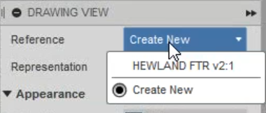
2. Having independent views means you can insert multiple independent parts lists on the same sheet.
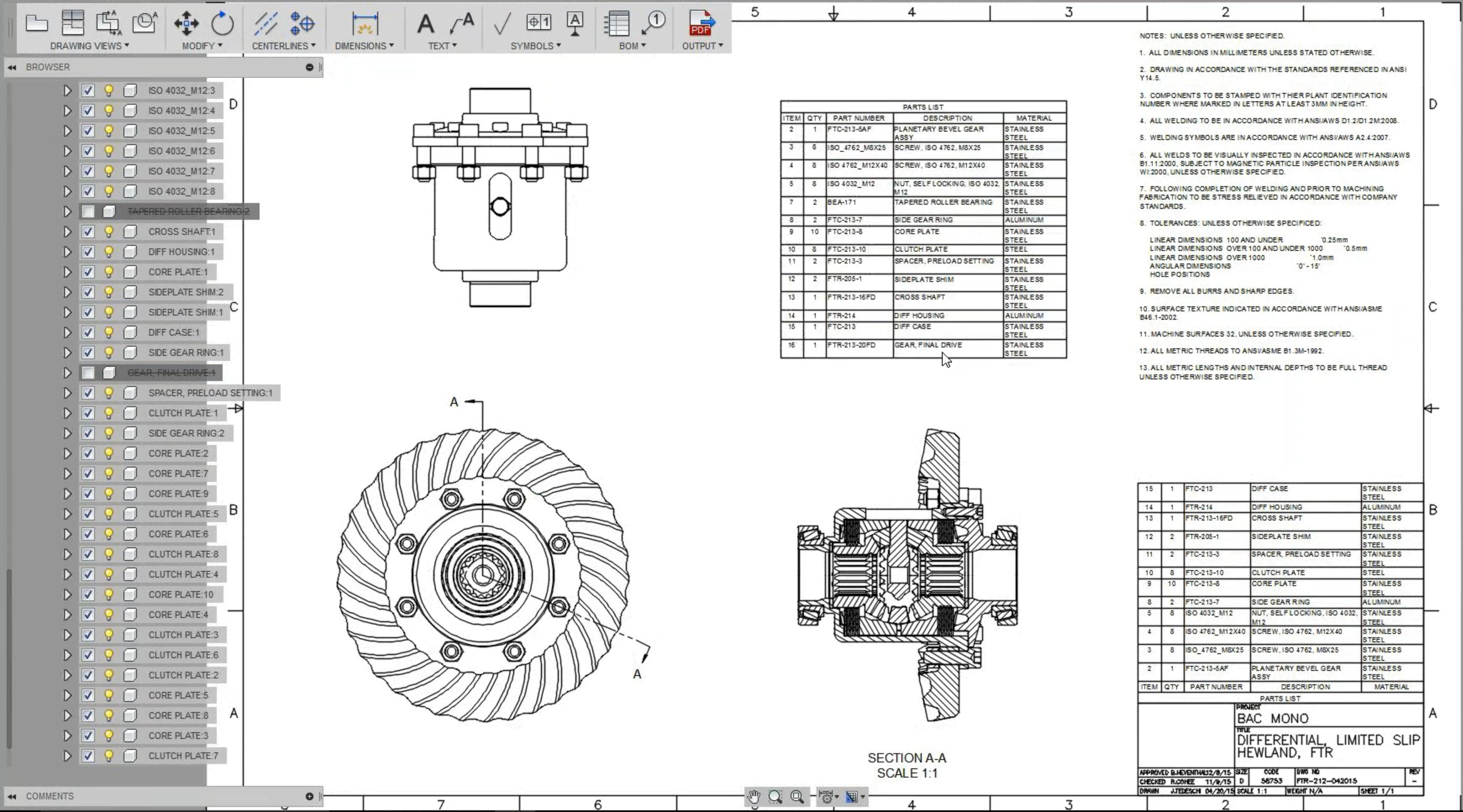
3. Hiding a component from the browser by unchecking the checkbox as opposed to turning off the light bulb will not only hide it within the view, but the component will also be removed from the parts list.
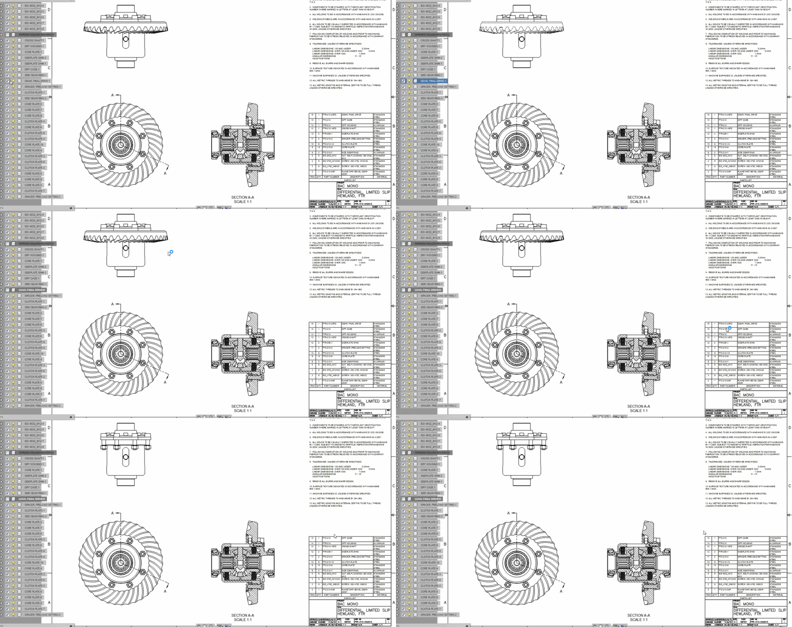
Notice that when you uncheck the component, it gets crossed out. Check it again and it will come back into the view and parts list.
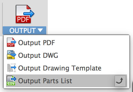
Speaking of Parts Lists, under the Output drop-down menu, you can now output your parts lists to CSV file and open it up in Excel, which is just dandy.
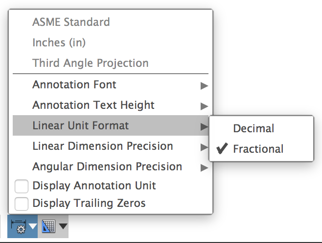
If you’re creating 2D drawings in inches, you can now use fractions instead of decimal values. Huzzah!
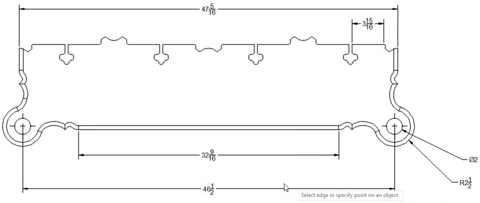
If you have custom named views saved for your Model Workspace, you can select one of those views in the Orientation drop-down menu when you create a new view on your sheet. Now you can also dimension, centerline, and centermark from them.
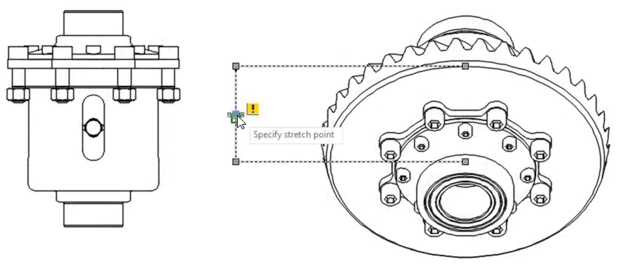
Oh and by the way, see that (!) exclamation mark in that drawing dimension? That’s one of those pesky disassociated dimension warnings Fusion keeps nagging you about. We’ve turned them off so you can work in harmony. You’re welcome.
New Objects To Cut options – Previously when you made cuts to a design where the cut is going through multiple bodies or components, yet you didn’t want certain ones to be cut, you had go through a really convoluted work-around to actually be able to select what objects you wanted to cut.
Now when you do this, a list will appear, showing all the bodies and components affected by the cut, with check boxes next to them so you can easily omit the ones you don’t want to be cut.
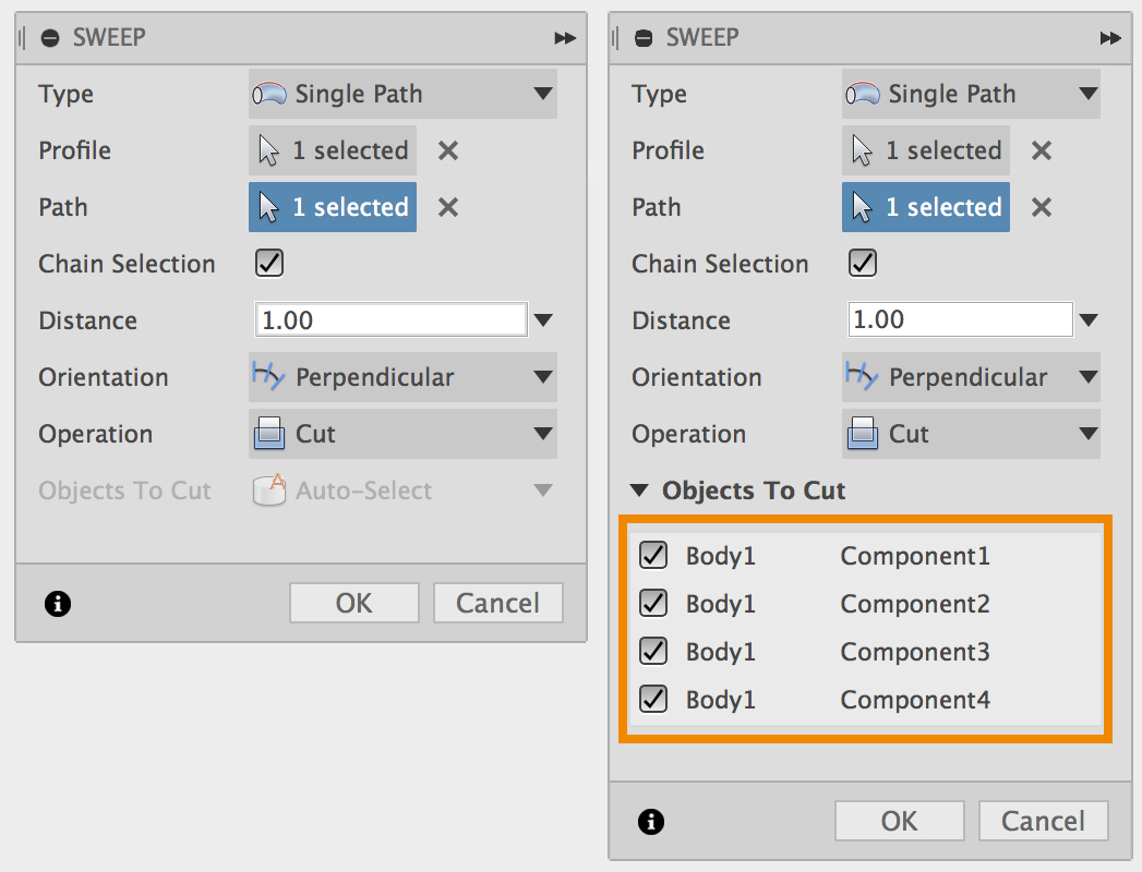
This option will appear in all cases where a cut is affecting multiple bodies/components (Sweep, Extrude Cut, or Boolean cuts). Keep in mind that what appears in that list is based on visibility, so if you have a certain body/component hidden and make a cut, those objects will not appear in the list. Once a cut is created, Fusion 360 will remember everything that was checked, so when you edit the feature, it won’t change the things that are cut or not cut.
We updated the engine that drives Fusion 360’s UI, which not only makes various UI elements look crisper on 4K displays, it will also allow us to work on fixing some of those irritating issues like Fusion jumping in front of all your windows and grabbing attention. We know, and we’re working on getting rid of that once and for all.
Previously there were only two roles supported within a project: Editor and Project Admin. Project Admin could do everything Editor did, as well as control member approvals and access settings. Now you can invite people as viewers only, so that they can be a part of your project, but only have access to view your designs, and not modify, download, or delete.
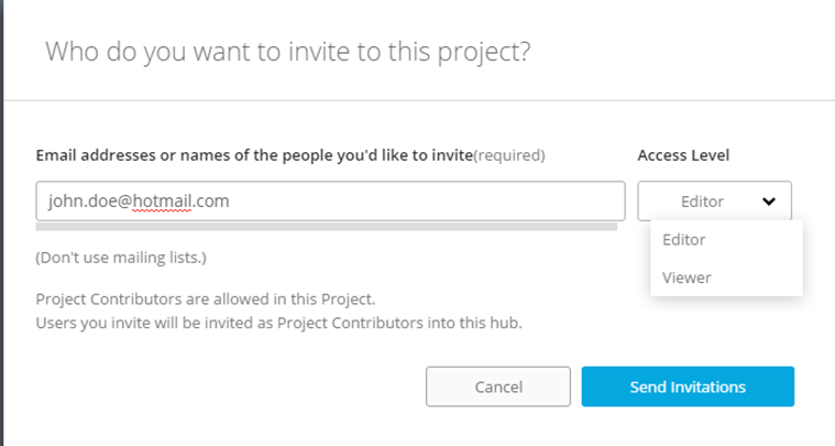
If you’re a project manager in a specific project, you can assign members as viewers under the Role options.
It will run on OS X 10.10 and newer, including macOS 10.12 Sierra. 10.9 is getting outdated and not supporting it means we can put our focus on improving performance and stability for more relevant Mac OS versions.
The easiest way to upgrade is to go to the Mac App Store and download the newest OS installer to get going. If you want to do some research before you pull the trigger, I’ve gathered a number of handy web pages that should help you get started.
Upgrading to macOS Sierra 10.12: http://www.apple.com/macos/how-to-upgrade/
Upgrading from 10.9 to 10.10: https://kb.iu.edu/d/bfbv
Upgrading from 10.9 to 10.11: https://discussions.apple.com/docs/DOC-8811
Our API now supports the new Extrude tool functionality released a couple updates ago. There are, however, some breaking changes, so if you have code based on the old Extrude tool, check out how you can fix it below.
There are a bunch of other API improvements that went out in this update, but being mindful of how long this What’s New post is, you can check out more details on API related fixes and improvements posted on the API What’s New page.
If you’re still reading this, then massive kudos to you for sticking it through. We’re always interested to hear what you have to say, so please post in the comment section below. We’re also looking forward to seeing you at Autodesk University, which is going to be awesome. We’re hosting a CNC class with John Saunders from NYC CNC, which is something entirely new this year. If you’re thinking of going, it’s not too late to sign up for a Discovery Pass! That class alone is going to be worth it.
Now fire up Fusion 360 and go play! And we’ll see you at #AU2016!
By clicking subscribe, I agree to receive the Fusion newsletter and acknowledge the Autodesk Privacy Statement.
Success!
May we collect and use your data?
Learn more about the Third Party Services we use and our Privacy Statement.May we collect and use your data to tailor your experience?
Explore the benefits of a customized experience by managing your privacy settings for this site or visit our Privacy Statement to learn more about your options.