
(v.2.0.16490) – June 22, 2023
We fixed an issue that caused some of you to wait around 15 mins for Fusion 360 to open.
(v.2.0.16488) – June 19, 2023
We fixed an issue within the Manage extension where Change Order creation was not operating as expected.
Some of you reported an issue within the Drawings workspace where attributes were incorrectly displaying as blank. This is now fixed.
Minor Product Update
(v. 2.0.16486) – June 11, 2023
This June we addressed key issues reported through our support channel, forums, Fusion 360 Insider Program, as well as our manufacturing Customer Advisory Board. Thank you everyone for your ongoing support! Let’s get into the key updates:
Manufacturing:
- We noticed an issue where the post engine wasn’t linearizing the tool end point when moving to the rotary axis limit. This is now fixed and should work as expected.
- We fixed an issue where NC Programs with a machine attached, and Machine configurations enabled would create incorrect post process outputs.
- We fixed a crash issue that occurred when clicking on a nesting error.
Design:
- We fixed an issue where auto_holeTopDiameter was no longer being set unless the computed thread parameter feature flag was also turned on.
- A few of you reported an issue where you were unable to import IPT files and variety of other file types using Open. This is now fixed.
Drawings:
- We fixed an issue where the “Reference” option was missing from the Rotate dialog within the Fusion 360 Drawings workspace.
Render:
- A couple of you reported an issue where local rendering was not starting on Mac since the May 2023 Major Product release. This is now fixed.
API:
- We fixed an issue where dynamically setting the resource Folder of a button using Fusion 360 API would kill the program.
Major Product Update
(v.2.0.16265) – May 30, 2023
What’s New in Fusion 360: May 2023 Overview
Live with the Experts: What’s New in the May 2023 Release
Come learn about new functionality and tools now available in the latest Fusion 360 updates in Design & Documentation, Manufacturing, Electronics, Generative Design, and Simulation.
During this 60-minute webinar, we’ll also dive into improvements around flexibility and control, programming efficiency, show off some tips & tricks, and open up the floor for LIVE Q&A.
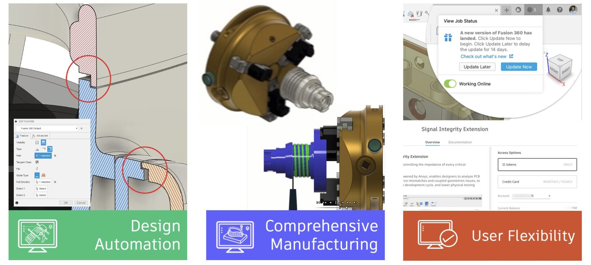
We have 2 sessions running on Thursday, June 8, 2023 for you to choose from, both identical in content, just at separate times. Click the links below to sign up. Looking forward to seeing you there!
Register for 10:00am UK | 11:00am CEST | 2:30pm IST
Register for 9am PDT | 12pm EST | 5pm UK
Usability
New: Snooze a product update

Many of you have been asking for this feature for a long time, and we’re glad to say that it is finally happening. After taking this current product update, you will be able Snooze (or “Update Later”) future product updates to a later time.
You can now Snooze an update for 3 days. In addition, paid subscribers, startups, and trial users can snooze an additional 11 days for a total of 14 days. As a rule of thumb, we recommend that you should stay up to date with the latest version of Fusion 360, not only to get access to the newest feature and improvements, but also to ensure that your version of Fusion 360 is always supported with the latest services behind the scenes. This is also why we’ve set the Snooze duration to a maximum of 14 days; going beyond that may cause version disparity issues.
When you are in the middle of an important task and want to minimize disruptions to the workflow, Snoozing a product update can help you and Fusion 360 maintain focus on the task at hand, and get the job done. Using Snooze also prevents you from needing to take Fusion 360 offline to avoid updates.
Learn more about Snooze.
Improved: Numbers now work in S-Key Search

Previously, when you typed a number in the S-key search box, Fusion 360 would not register it, and nothing would show up in Search. You can now use numbers like “3” to get results for commands such as “3-Point Circle” in Sketch, or “3D Print” in Design.
Resize Command Windows from any Edge or Corner

Traditionally, Fusion 360’s command dialogs have been limited in how they can be resized – a horizontal anchor in the upper left, and a diagonal anchor in the lower right (but only when undocked). This created difficulty when resizing the height of docked commands and was especially challenging with larger dialog windows.
With May release, you can now resize commands from all edges and corners (providing there is space to do so). Command dialogs will remember their size and position until Fusion restarts.
High-Resolution Canvas Graphics renamed and enabled by default
Preferences > Graphics > Display
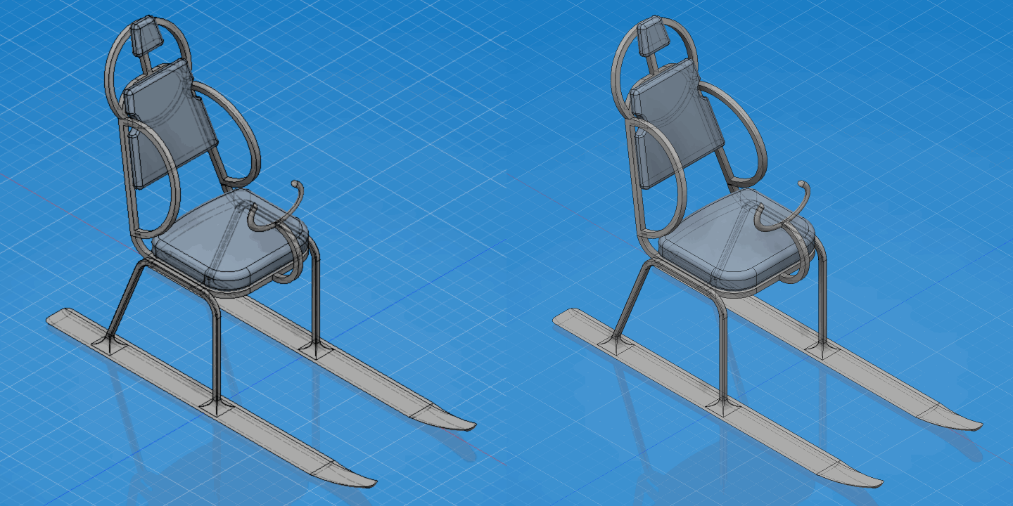
The following changes have been made to Fusion 360’s default graphics options:
- The “Use high-resolution graphics” option has been renamed “High-resolution canvas graphics on high DPI displays” to clarify that it only applies to the modeling canvas when DPI scaling is in use by the operating system.
- The option to use “High-resolution canvas graphics on high DPI displays” is now visible in Preferences at all times, allowing you to toggle it even when not actively using a high DPI display; previously, the option would only appear if Fusion was launched in High DPI mode, and would not appear even if a Retina display was enabled.
- High-resolution canvas graphics are now enabled by default when DPI scaling is in use; you may still disable them in Preferences to prioritize framerate performance over visual quality.
- “Limit effects in high-resolution graphics” is now disabled by default.
- Reminder: High-resolution canvas graphics are currently only available for macOS with Retina scaling, and Windows with Fusion 360’s High DPI Scaling preview enabled. The option will be available to all Windows users in Summer 2023.
Performance Improvements
Fusion 360 is now faster than ever! Here are some key highlights for this update:
- Open: Up to 47% performance improvement when opening design files under Manufacture workspace by default.
- Assembly: Selecting 2nd component under Pattern/Mirror/Move command can be now done immediately for some design files, while previously needing about 218 seconds (about 3 and a half minutes).
- Up to 2.4x performance improvement when doing Break Link for design files.
- Switching to motion tab in Edit joint dialog has improved from hang to instantaneous for some design files.
- Modeling: There’s about a 20%-64% performance improvement for Loft preview generation with some design files.
- There’s about an 83-114% performance improvement when using Mirror & Pattern within a design file with many bodies selection under direct modeling.
Design
New Plastic Lip Feature (Product Design Extension)

With this update you will now be able to easily create a Lip within the Plastics workspace of the Product Design extension. When designing a product, you may want to create a feature to fit two parts together. That’s where the Lip tool comes in. The Lip tool creates a raised lip, recessed groove, or interlocking combined feature on one or two solid bodies. You select an edge and a guide to place the lip or groove on a body, then specify the feature dimensions. If your part has a Plastic Rule applied, dimensions are automatically applied. Optionally, select geometry to define the extents of the path, then select an outcome option.
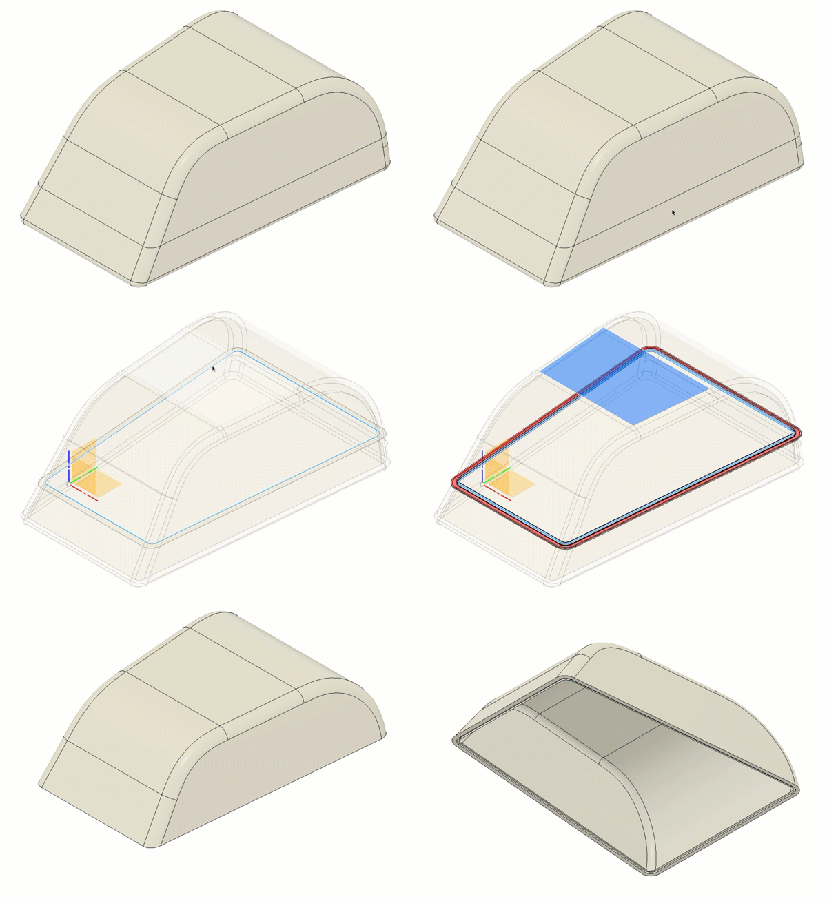
Tips to create a Lip and Groove feature:
- Assign a Plastic Rule before creating a Lip feature.
- To create a lip and groove together, ensure the two bodies are touching so the edges line up and the faces are normal to each other. For example, a box that you Shell and then Split Body.
- Select the inside edge to place the Lip feature so the reveal is on the outside of your design.
- For Lip And Groove type, the groove dimensions are automatically determined by the lip dimensions and clearance.
- For Pull Direction guide type, ensure the edges are tangent continuous.
Learn how to create a Lip and Groove
Core Modeling Commands now available for Edit-in-Place
Previously when you were working with Edit-in-Place workflows, you did not have all the core modeling tools at your disposal. This update remedies that by enabling the following commands in EIP (Edit-in-Place) mode:
- Solid > Create > Rib
- Solid > Create > Pipe
- Solid > Create > Thicken
- Solid > Create > Boundary Fill
- Solid > Modify > Replace Face
- Solid > Modify > Silhouette Split
- Solid > Modify > Align
- Solid > Modify > Simplify > Remove Features
- Solid > Modify > Simplify > Remove Faces
- Surface > Create > Loft
- Surface > Modify > Extend
- Surface > Modify > Stitch
- Surface > Modify > Unstitch
- Surface > Modify > Reverse Normal
- Inspect > Interference
- Select > Select By Name
- Select > Select By Boundary
Improved Mesh Conversion for Volumetric Lattices
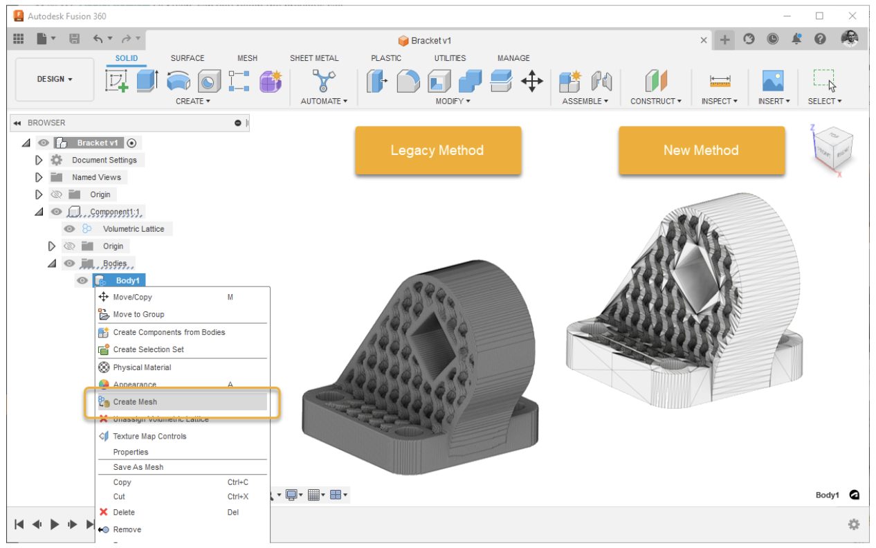
Creating a mesh is a key step when you use Volumetric Lattice, as it allows you to use the tools in the Mesh tab to manipulate your design and export the mesh to 3rd party slicers.
Fusion 360’s original “Create Mesh” command used a marching cubes algorithm to create a mesh body from bodies with volumetric lattices. The issue with this approach was that it often created stepping effects and other artifacts on otherwise smooth faces resulting in poor surface finishes when 3d printed. In this version, we are changing our meshing approach and releasing a new method for converting volumetric lattices to mesh bodies. The new and improved meshing method for volumetric lattices creates higher quality mesh on the surface of parts and an overall reduced triangle count on the mesh body.
Parameter table now supports conditional expressions
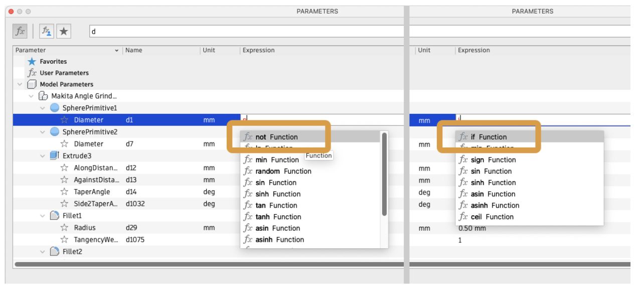
The parameter table now supports conditional expressions and logical operators:
- if (expression; value if true; value if false)
- and/or
- not(expression)
Improved Automated Modeling UI
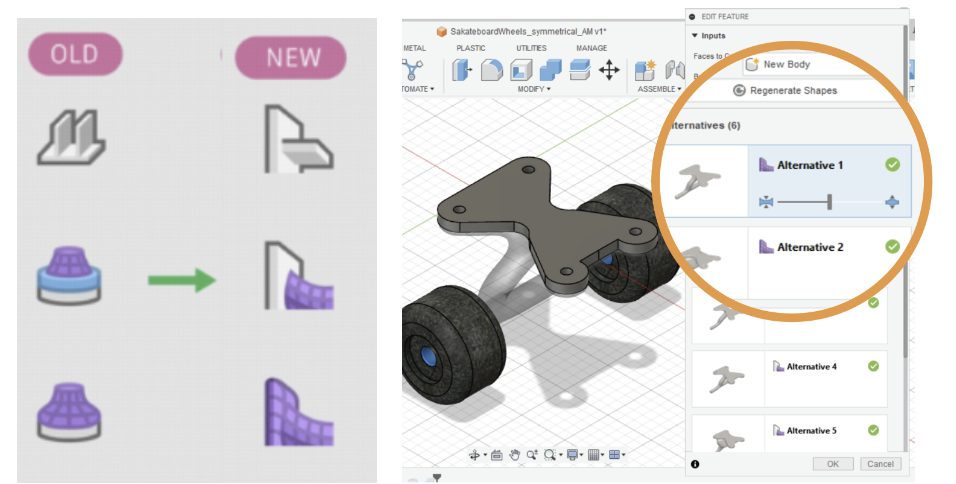
Now within Automated modeling you will see new icons for alternatives for easier recognition of alternative types (smooth, crisp, plate), as well as improved error handling in case of service unavailability.
Electronics
New image print configuration in CAM with preview
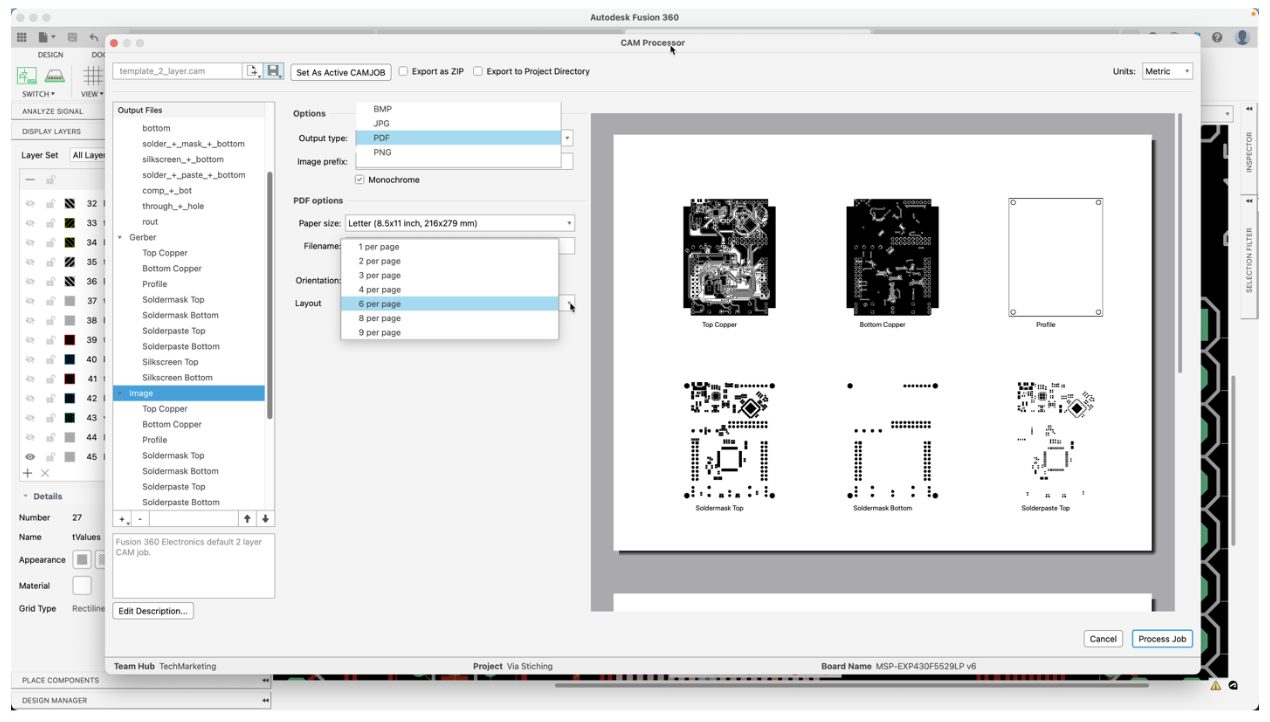
Fusion 360 electronics CAM Processor allows you to generate manufacturing data of your printed circuit board in industry-compatible formats such as ODB++ and Gerbers. The CAM Processor is highly flexible; you can change or update sections for required output specifications. The outputs will automatically include your Bill of Material, Pick and Place, and documentation images. The documentation images can now include more than one layer set page. This enhancement of the CAM Processor enables you to efficiently create better manufacturing documentation images of your board in a more practical format.
Additional Layer Set options for 3D PCB Visualization
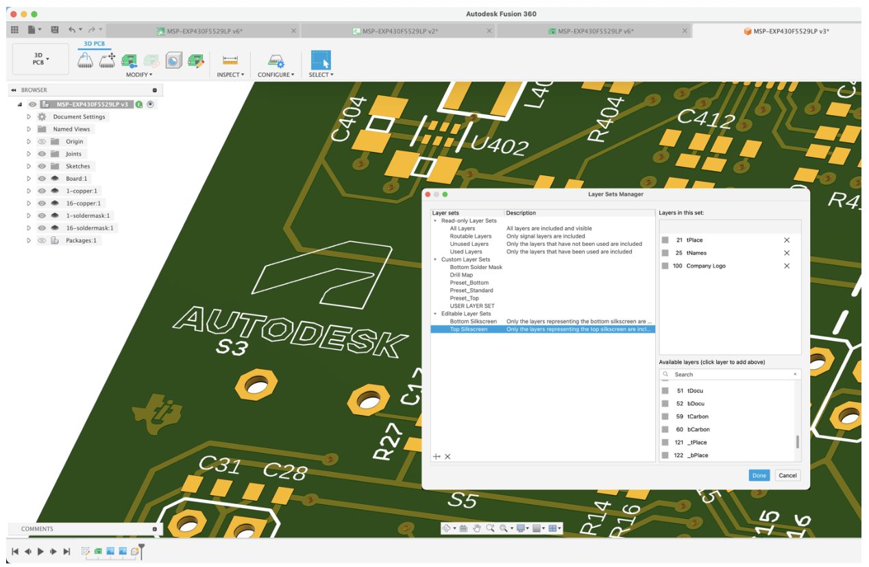
Many of us have grown fond of working with Fusion 360 electronics and using the 3D model to help with the layout. This realistic perspective makes it so much easier to fine-tune the component placement. Many contacted us requesting more control of what would appear on the silkscreen of the 3D model. Previously, we only supported the conventional Place and Name layers for the top and bottom silkscreen. In this update, you will notice that in the PCB editor, the display command has a section for the Editable Layers Sets. You can now select which layers will appear as silkscreen in your 3D models. Giving you more control of your layer management for notations such as fabrication details, company logo, copyright details, and much more.
Schematic Symbol Pin Breakout Now Use Standard Command Dialogs
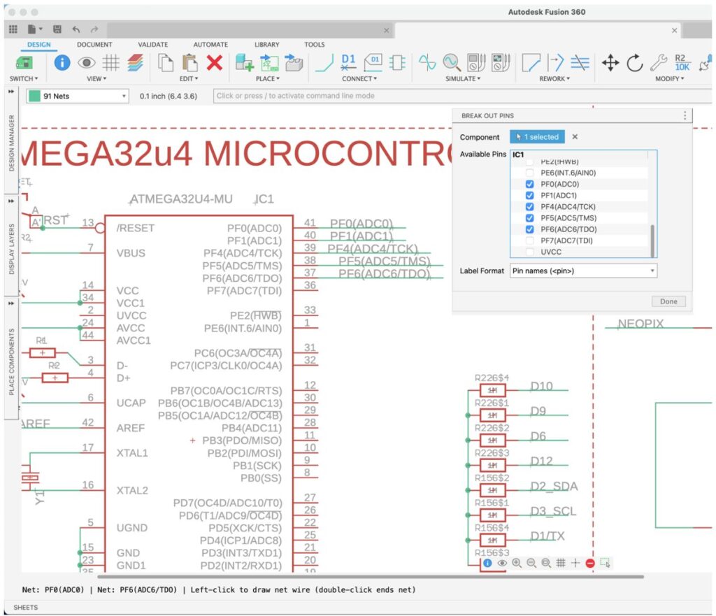
The Pin Breakout feature can improve the clarity of the schematic by making it easier to read and understand. By breaking out the individual pins of a component, you can see exactly how they are connected to other parts and how the overall circuit is structured. We have revamped the pin breakout command for this update into a more accessible and flexible dialog box. With the list of pins of the selected components, you can easily select the pins you want to break out and which NET naming convention you want to use. This will help you break out components with large pin counts into a simple format and speed up your design time without sacrificing organization.
MOVE by arrow key during copy/paste preview
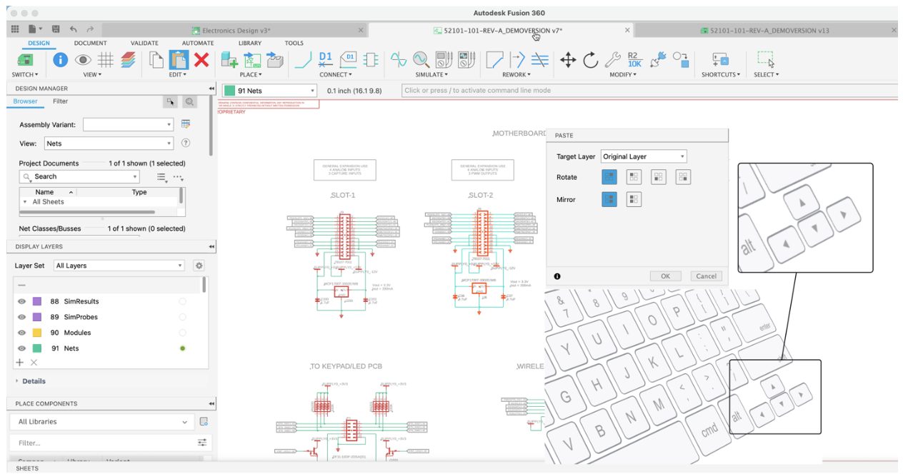
In earlier versions of Fusion 360 electronics, we added support for moving selected or new assets using the arrow keys. Using the arrow keys provides much-needed precision when placing components in a specific location. Copying and pasting to replicate circuit assets or a section of your schematic design saves time and effort.
In this update, Fusion 360 electronics now supports using the arrow keys for pasted assets. After completing that single-channel circuit, you can easily copy and paste to replicate it seven more times, keeping the symmetry you want to use for proper documentation for the new 8-channel system you are working on. Using the arrow keys, the paste command will move the assets one grid point at a time. The same actions can be used in the PCB and Library workspaces. This will help you place your components precisely where they need to go without using your mouse.
Token Flex Now Available for the Signal Integrity Extension powered by Ansys

Some of you will remember that we implemented the Signal Integrity extension powered by Ansys last year. Adding this extension to your electronics workspace will give you the analysis capability of your critical traces on your circuit board carrying high-speed signals. The signal integrity extension provides you with visual insight into specified impedance as well as getting details such as resistance, time delay, length, and much more during your routing process. You no longer have to review your signal integrity requirements as a post-process task. Sign up for our 14-day trial of this valuable extension. Access to the signal integrity extension is now possible using our token flex system.
Learn more about our token flex system.
Zoom to fit off-center DXF imports

Fusion 360 will now zoom to fit DXF when imported to schematic. This helps when the imported file is not centered, making it so that the content is properly in view.
Improved Tab Switching Performance
We improved overall performance for switching workspace tabs in the Electronics Design workspace. The exact improvement percentage depends on machine, design, and other factors, but overall tab switching can be seen to be noticeably faster than in previous versions.
Generative Design
Improved Symmetry Constraints
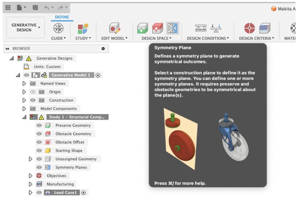
Within this update you will see an improvement in communication and error handling in cases of not supported symmetry planes for 2 and 2.5-axis milling setups. Additionally, you’ll find that the symmetry feature is now pinned to the main toolbar by default making it easier to access.
Learn more about Symmetry Plane.
Improved Frequency Limits in Experimental Generative Solvers and Features Preview
In this update, the frequency limit objective will now produce results for all manufacturing methods, except the Die Casting preview. This functionality will allow you to specify a minimum natural frequency that your design must exceed for its intended application.
Learn more about Experimental Generative Solvers and Features.
Simulation
New Report Capability for Injection Molding Simulation
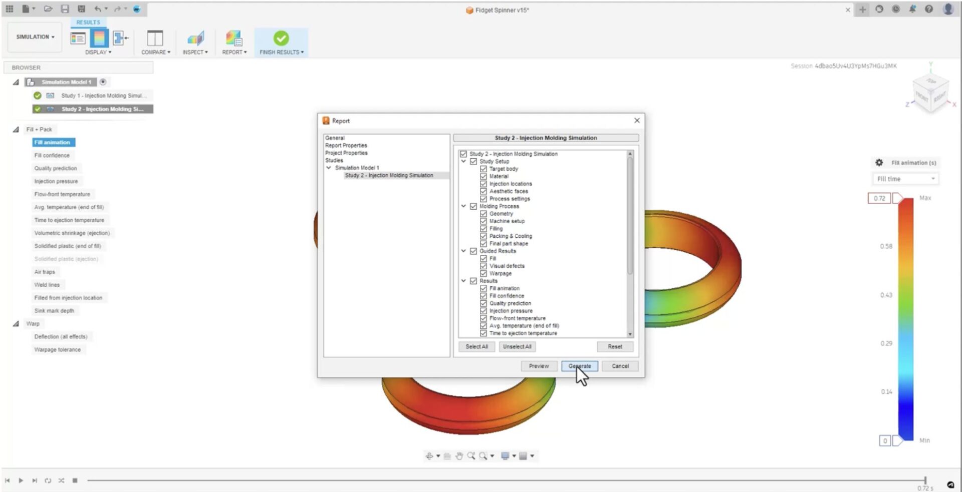
You can now generate reports for Injection Molding Simulation studies. The report generation tool allows you to create customized reports and pick and add the information you wish to include in the report. You can preview how your report would look like and make necessary changes before you generate the report which can then be saved on the cloud and/or locally on your computer.
Improved Simulation Cloud Solve Performance
We have made improvements in the simulation cloud solve pipeline, where we are now using faster cloud machines for Simulation, which will improve the cloud solve performance for simulation jobs by around 20%.
Updated Injection Molding Simulation material database
The Injection Molding Simulation material database has been updated:
- Total number of Materials: 12663
- Total number of Manufacturers: 594
- Total number of New Materials added: 215
- Total number of Materials updated: 199
- Total number of Materials deleted: 75
- Manufacturers deleted: 2 (Exxon Chemical, Hanwha Total Petorchemical Co. Ltd.)
- New Manufacturers added: 10 (Sumika Polymer Compounds UK Ltd, Sumika Polymers North America, SunAllomer Ltd, Hanwha TotalEnergies Petrochemical Co Ltd, Plaskolite West, Sabic, SEKISUI KYDEX, Styrenix Performance Materials, Sumika Polycarbonate Limited, Sumitomo Chemical Asia)
Improved messaging for Injection Molding and Electronics Cooling studies when results are not visible
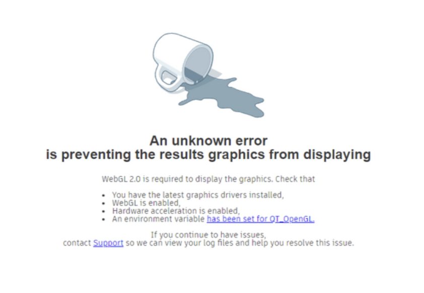
There have been situations where you were not able to see any results for Injection Molding Simulation and Electronics Cooling Simulation after the solves are completed. Previously, you would see an empty window with no indication of what might be wrong. We have now added a user-friendly message on possible causes for results not showing and actions you can take to resolve it.
Drawings
New Copy with Drawings
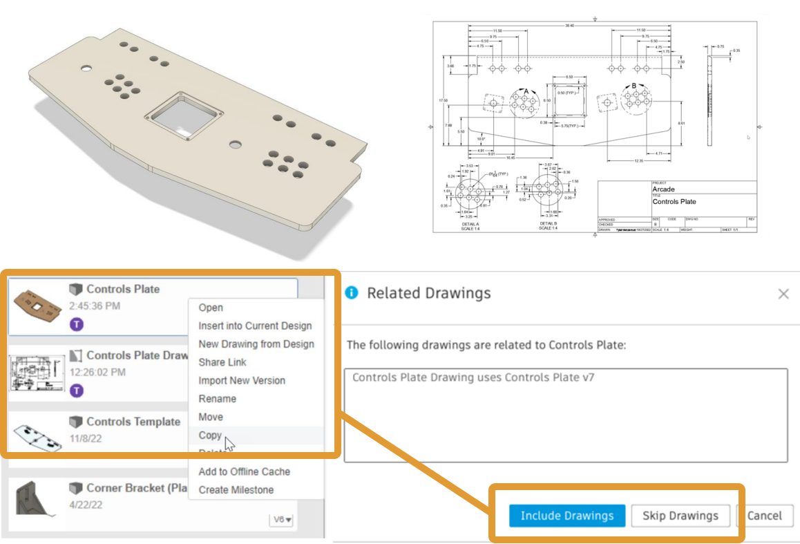
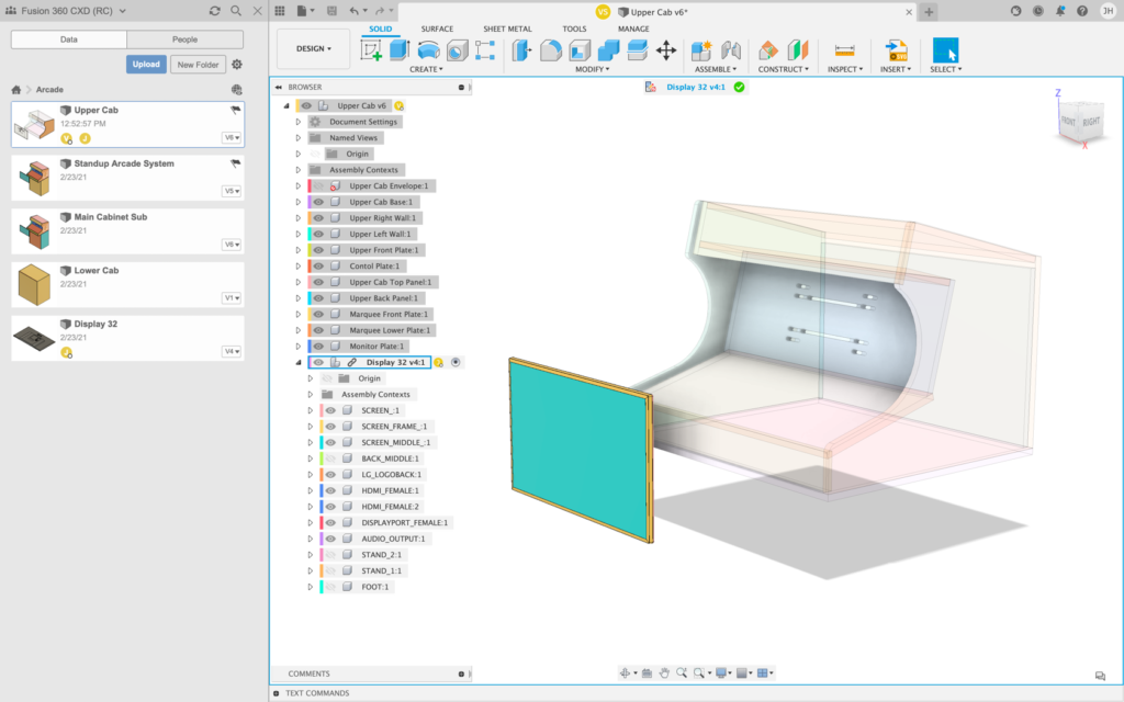
We’re excited to announce the addition of Copy with Drawings, an enhancement to the Copy Design workflow that lets you copy a design and its related drawings.
In the image above, you can see the Controls Plate is from a previous project and has a detailed drawing. You might need to create a new variation without the trackball opening in the center of the plate. When you copy the Controls Plate design from the Data Panel, you can now include its related drawings. To dig a bit deeper, check out our recent blog post: How to Copy a Drawing in Fusion 360.
Learn more about copying designs.
Add-in Highlight: Bommer
Our friends at Bommer are putting the finishing touches on their own conditional expressions for formulas inside a Bommer bill of materials. Their feature launches next week, but in the mean time here’s a video quick tip from their “spokesbird” Bill to show you how it works: https://links.getbommer.com/bills-tips-conditional-statement
Manufacturing
New Rotary Pocket Multi-axis Strategy (for Machining Extension)
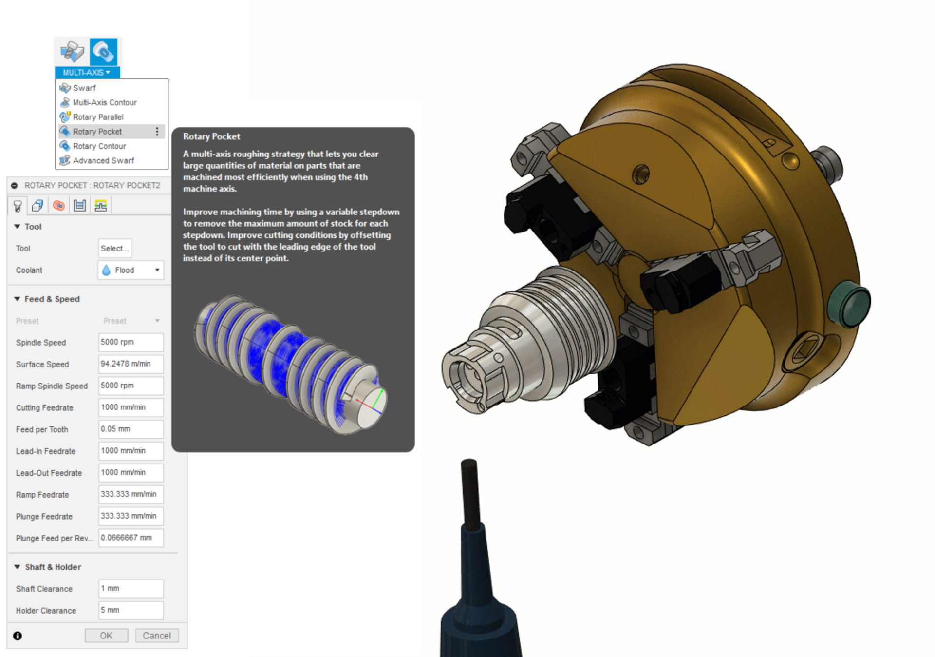
We love it when a new multi-axis toolpath strategy makes it into Fusion 360 and becomes available for you all to use. As of this update, Rotary Pocket, a new simultaneous 4 axis roughing milling strategy, is now available within the Fusion 360 Machining Extension! This feature allows you to clear large quantities of material on parts that are machined most efficiently when using the 4th machine axis.
Found via the Milling tab under the “Multi-Axis” drop down list of strategies, Rotary Pocket is commonly used on roughing complex parts made from cylindrical or conical shaped stock material.
Learn more on how to generate a Rotary Pocket toolpath.
New Rotary Contour Milling Strategy (for Machining Extension)
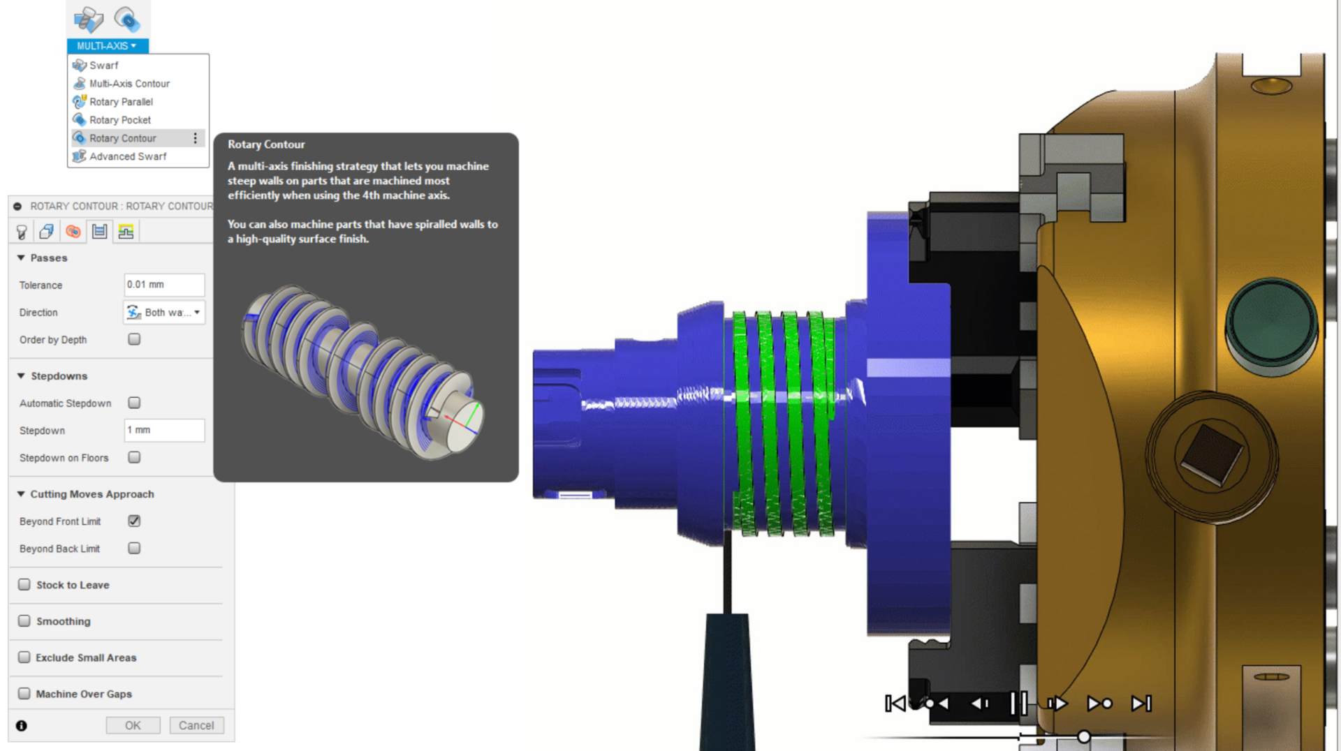
Right below Rotary Pocket is the introduction of another new strategy called Rotary Contour. The new Rotary Contour milling strategy is designed to finish the machine steep walls using simultaneous 4 axis machines. It is similar to the existing 3D Contour strategy, however it differs in the fact that it produces 4 axis cylindrical or conical slices, opposed to Z planar slices. Therefore, it is commonly used for parts made out of cylindrical or conical shaped stock material on a 4 axis machine tool. Try it out today within the Fusion 360 Machining Extension.
Learn more on how to generate a Rotary Contour toolpath.
Additional 5 axis options for the Multi-Axis Contour Strategy Preview (for Machining Extension)
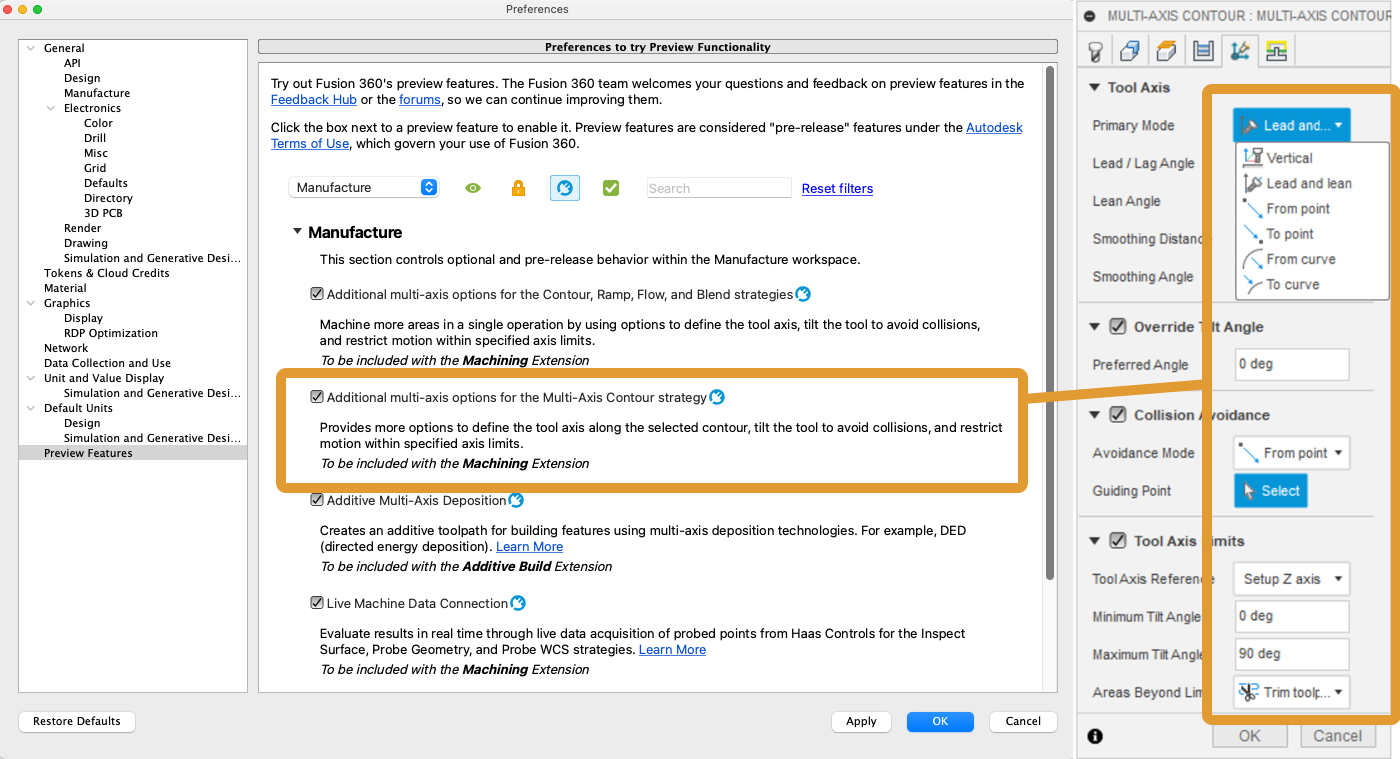
The Multi-Axis Contour milling strategy now has a more comprehensive set of 5 axis options to try as preview functionality. It is now consistent with most of the other finishing strategies. The primary tool axis can now use the To or From Point/Curve. Automatic collision avoidance can be switched on to avoid collisions between the tool assembly and the design model. To try these options, check the “Additional multi-axis options for the Multi-Axis Contour strategy” box in the Manufacture section of the Preview Features. Note that this preview works only for those of you with the Machining Extension turned on.
New Profile-Only Passes for Flat Toolpath Strategy

The Flat toolpath now has the ability to calculate profile-only passes on regions where vertical/steep and flat regions meet. You get the same benefits as using the 2D Contour but you also get the benefits of the toolpath being model aware. This new addition to the flat strategy can also be used as a wall finishing strategy when applying Multiple Depths in the passes tab. The Flat strategy also benefits from having access to rest machining from a previous operation, resulting in a more accurate in-process stock simulation.
Improved Turning Tool Annotated Images
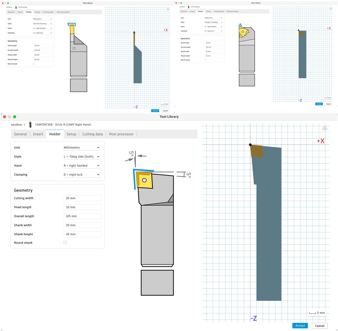
If you make turning tools in Fusion 360, you probably have seen some…low fidelity representations of turning tools in the images that we use to show you which tool dimension you’re editing. Recently, we collaborated with our talented design team to update these images with much more detail and to match real tools much more closely.
Tool Library – Persist User Expressions (Preview feature)
Persist User Expressions stores the expression that you enter into the tool library when defining parameters like tool geometry or feeds and speeds in a Preset. When you close the tool library or even Fusion 360 and reopen, the expressions will still be there when you access the parameter.
This helps you view the original intent of the value – seeing that it was referencing another parameter for example. It also means if you change a parameter that’s referenced in another parameter’s expression, they will both update! So, for example, feeds and speeds expressions that reference the tool diameter will update if they are copied and pasted to a new tool. Nice!
In this update, we made this feature flag on by default, so everyone will see this functionality unless turned off explicitly. If you choose to turn this feature flag off, please reach out and tell us why! We are planning to release this fully in the next major release and want to know your thoughts if something isn’t quite right.
Note: if you previously had the Persist Expression Preview feature on, you will notice that with this update we no longer pass the expression from the Tool Library into the expression dialog. This was an intentional change due to differences in the parsers and will prevent unexpected changes in value until those differences can be reconciled.
Learn more about User Expressions within the Tool Library.
Allow no-dragging in a turning profile roughing rest machining toolpath
We added the ability in turning profile roughing operations to turn on the no-dragging option when rest machining is enabled.
Existing trace toolpaths will now have extensions applied
Start and end extensions have now been enabled for the 2D Trace strategy. As a result, existing 2D Trace toolpaths might have extensions applied with no warning, if regenerated. This can cause gouging if the new toolpath happens to collide with the model or fixture.
Improved: Dynamic Preview (Preview feature)
We have a handful of improvements to the dynamic preview added to the tool library last release cycle, including:
- Reasonable thickness of turning tools, especially when in inches
- Better scale of the compensation point (no longer in the way!)
- Highlight the shaft section being edited for tools and holders
- Overlapping triangles of turning tool insert and holder should display better
We are also turning this feature flag ON by default! We expect that there may be some hardware issues or hiccups that were hard to identify with the limited hardware we have to test against. If you run into issues, you can turn the FF off to continue your work, but please also let us know that you’re experiencing issues so we can work on fixing them. We can’t wait for you to see your tools in 3D!
Learn more about the Tool Library.
Geometry Selection Fixes
In January of 2023, we introduced a major change in how you select geometry in the Manufacture Workspace. Continuing from the improvements introduced in the April product update, this release includes a further series of enhancements to the Geometry Selection functionality:
- Geometry selections didn’t apply Extension lengths to trace toolpaths issue fixed
- Chain selection did not apply Extension length to Trace toolpath issue fixed
- 2d Pocket / Adaptive “Order by Depth” was not working for some selection methods issue fixed
- Silhouette selection gave empty toolpath for 2D Pocket strategy issue fixed
- 2d Contour was not recalculated if side was changed fixed
- Single click’ chain selection ignored user defaults issue fixed
- Various direction arrow display fixes
- Missing chain preview issue fixed
- Display problems with CAD model and WCS with some selections fixed
- GF preview was missing after switching Passes tab to Geometry tab issue fixed
New and Improved Post Processors Update

Looking for the latest post processors and machines updates? This May we released a ton of new updates and improvements to many of the open-source Post Processors and Machines we offer for free. Within this release you will find improvements to generic post processors, mill-turn post processors, and additive post processors. You will also notice we added many new Machine Configurations to our machine library to allow you to define your available machines and resources and automate the settings in your Job Setup. Additionally, we updated and improved our Workholding library, and improved functionality around the Autodesk CAM Post Processor engine.
To learn more check out the forum post here.
Additive Manufacturing
3mf export from Manufacturing Workspace Now Includes a Thumbnail

Now when you export a 3mf from your additive setup, you will notice that the 3mf file has a thumbnail view associated with it, making it easier to identify what the design is before opening the file. With this release Fusion 360 will embed an isometric thumbnail image with certain machine files it creates. This makes it easier to identify which file you are printing on your 3D printer when a USB file has multiple sliced files to print.
Learn more about how to export an additive build to a 3MF file.
Items selected in the browser are now highlighted in canvas in Additive MFG
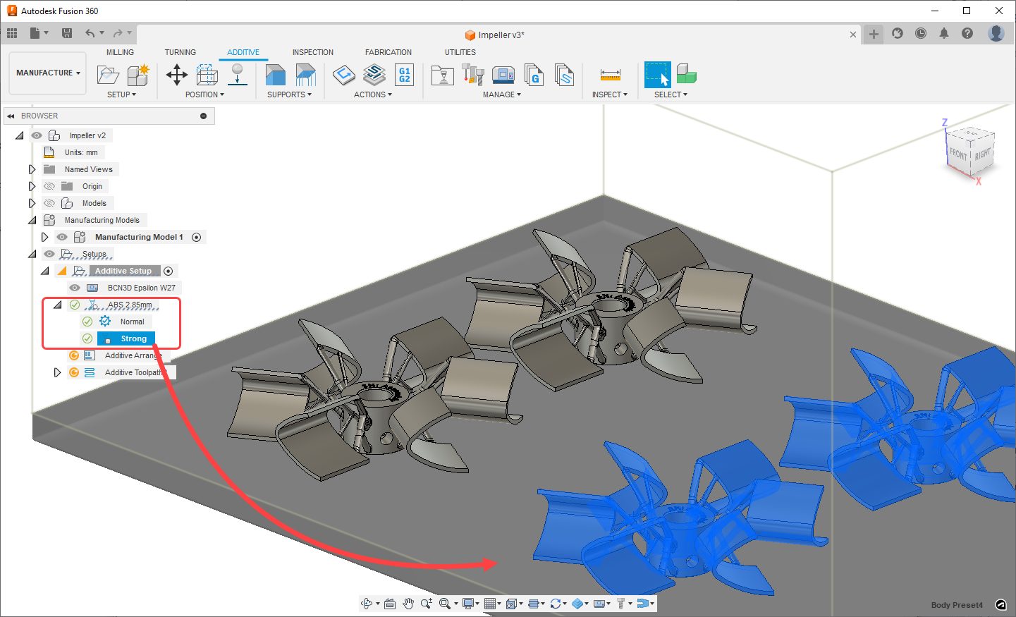
In additive manufacturing, you can assign a print setting to your setup after selecting your Machine. These print settings could have multiple presets (example: normal vs strong) with varying settings slicing and toolpath related parameters (Examples: infill type, density, number of contours.) In an Additive Manufacturing Setup, you can choose to assign unique body presets to a given body.
With the May 2023 release, when you select a Body Preset in Fusion 360’s browser, you will be able to identify which bodies utilize this preset, as the associated objects will be cross highlighted in canvas.
Learn more about how to assign build strategies.
FFF support structures can now have unique slicing settings per support type
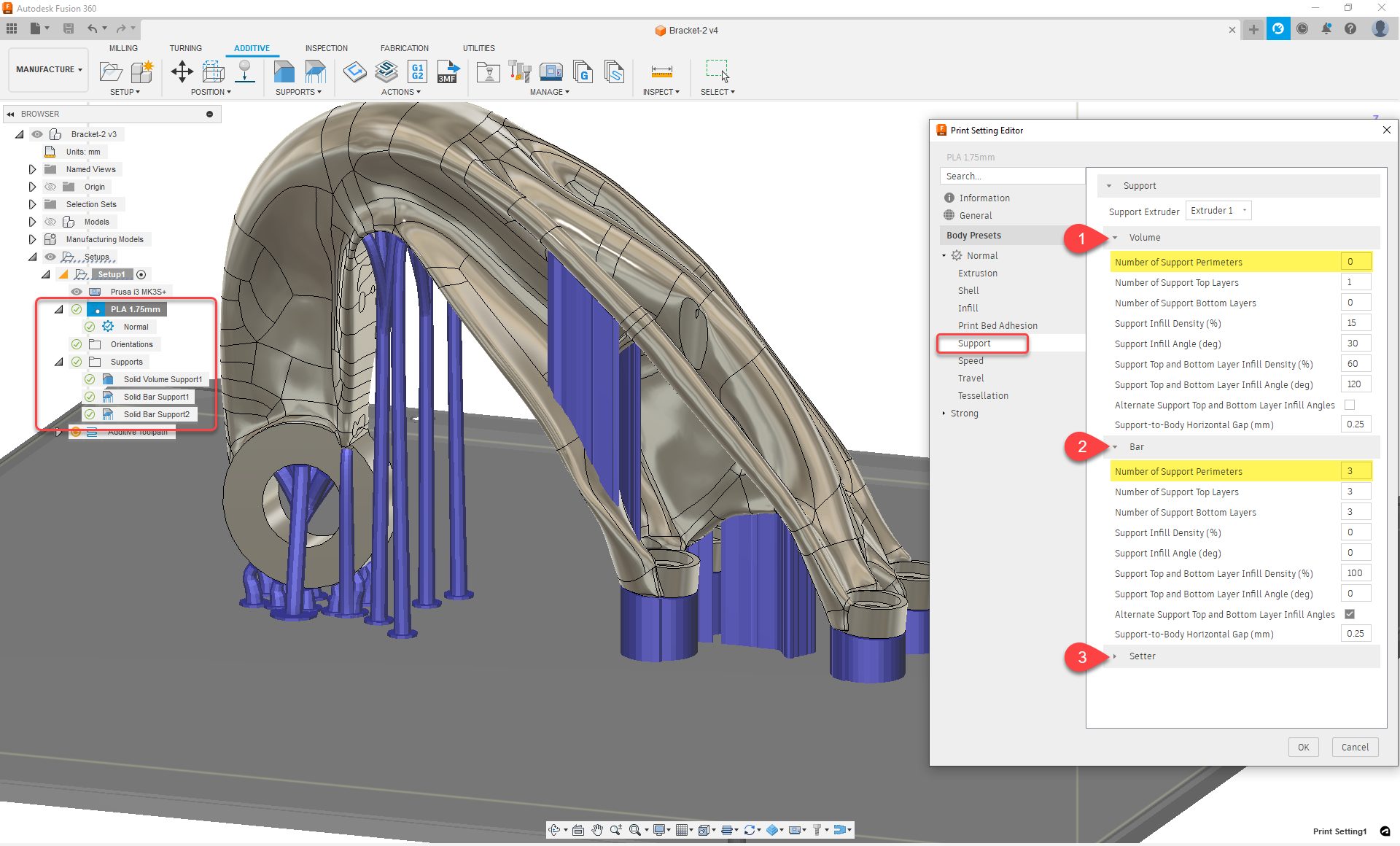
When working with Fused Filament Fabrication (FFF) printers you can use one of three support types: Volume supports, Bar supports, and Setter supports. In the past, the print setting assigned to a given body would dictate how the attached support structure would be sliced. This method worked fine if you only used a single support type per body (example: only volume supports), but if you wanted to mix and match support types on the same body, you would not have the control you needed for each support type.
With this release Bar, Volume, and Setter supports have their own respective parameter groups in the ‘Supports’ tab of the print settings. Using these settings, you can now slice supports in unique ways, and control how they are sliced (example: assign 3 perimeters to bar supports vs. 0 to volume supports). This will give you a lot of flexibility to combine different support types in a single build and grant you more control over support slicing.
Learn more about how to edit a print setting.
Component selection improvements to Additive Arrange
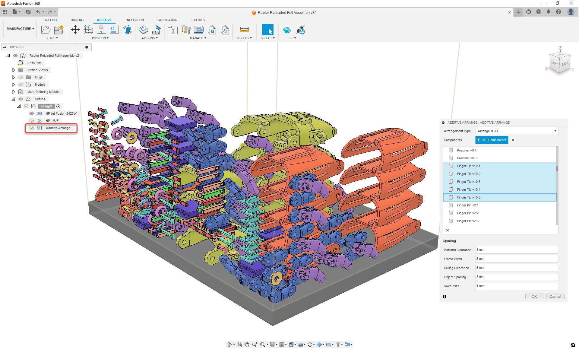
When preparing a 3D print involving multiple components, object placement within the build volume is an important part of the workflow. In Fusion 360, after creating an additive manufacturing setup, you can use the Additive Arrange feature to automatically pack parts using 2D or 3D arrangement methods.
With this release, you will now be able to see a list of all the components you are arranging within the Additive Arrange dialog. You will also be able to add/remove components from this list with ease.
Learn more about arranging components for additive manufacturing.
Additive Slicing performance boost for Volumetric lattices
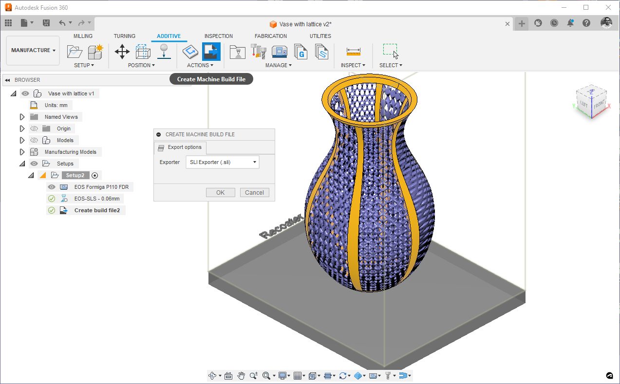
Slicing an Additive Setup that contains a model with a volumetric lattice is an important step for manufacturing such components. Through slicing, you convert your models with Volumetric data to slice data, and later can create an additive toolpath for 3D printing. As models with volumetric data tend to represent complex geometries, slicing such models is a time-consuming task.
With the latest release of Fusion 360, the slicing performance of bodies with Volumetric lattices has been significantly improved. Without compromising the resolution of the sliced outcome, bodies with volumetric lattice data can now be sliced up to 8 times faster.
Automated Arrange (Public Preview for Nesting & Fabrication Extension)
Automated Arrange provides a quick and improved way to create manufacturing setups for the arranged layouts. Moreover, creating an arrangement no longer moves the original components. Instead, it creates new instances for the arranged components. This prevents “breaking/disassembling” of the model and allows for side-by-side viewing without needing to manually create a copy of the model. Besides storing the Arrange results on the timeline, it will also create the corresponding Arrange and Envelope nodes in the browser tree (contained under an ‘Arrangements’ node).
For those of you that also have the Nesting & Fabrication Extension enabled, the Automated Arrange Preview unlocks additional functionality – Quantity, Priority, and Filler.
- Quantity – Specify the number of component instances to arrange.
- Priority – Specify the relative importance of a component to be included in an arrangement
- Filler – Specify what components can be added to further minimize the wasted material once the regular components have been arranged.
Notes: Arrangements can only be created in the Design Workspace, and then consumed in the Manufacturing Workspace. Arrange feature is no longer available in the Edit Mfg Model environment. To ensure that results do not overlap the model use the ‘Offsets’ option on the Envelope tab
Learn more about Automated Arrange.
API and Add-Ins
New API Support for Rendering Workspace
Many of you have asked for this and we’re happy to say that the API now supports most of the functionality available in the Render workspace. You can define all the settings and start local renders, however, there are two things not currently supported: in-canvas rendering and cloud rendering.
Support for in-canvas rendering is planned, but there are no current plans to support cloud rendering since it requires Flex Tokens and becomes much more complicated. There is also a difference in how the local rendering works. When you render locally through the user interface, it creates the rendering locally but then stores the result on the cloud. You can do the same when using the API or save the result to a local file.
New API support for creating and editing Canvases
The Fusion 360 API now also supports creating and editing canvases within a component.
Improvements to the Manufacturing API
For those of you who use Fusion 360 API for automating your manufacturing
workflows, you can now create scripts (Python/C++) to:
– Set “Fixture attachment” during a setup creation.
– Use CAD parameter for an operation input for geometry selection.
– Utilize Hole recognition.
– And if needed, delete operations and setup.
Please refer to the Fusion 360’s online API documentation to learn more about What’s New this release and for details about how to use these improvements and example scripts.
Our friends at Bommer are putting the finishing touches on their own conditional expressions for formulas inside a Bommer bill of materials. Their feature launches next week, but in the mean time here’s a video quick tip from their “spokesbird” Bill to show you how it works: https://links.getbommer.com/bills-tips-conditional-statements
Customer Reported Fixes
See What’s Coming Next
2023 Fusion 360 Roadmap
Get a sneak peek at what’s to come in the 2023 Fusion 360 Roadmap and an understanding of the “why” behind the features we’re investing in.
DISCLAIMER: Roadmaps are plans, not promises. We’re as excited as you to see new functionality make it into the products, but the development, releases, and timing of any features or functionality remain at our sole discretion. The projects mentioned in this roadmap are highlights and do not account for ongoing efforts like bug fixes, platform, and service maintenance. These roadmap updates should not be used to make purchasing decisions.
Become a Fusion 360 Insider

Want to engage more with the Autodesk community and test out the latest build one month before it’s released to the general public? Check out the Fusion 360 Insider program! The Autodesk Fusion 360 Insider Program enables you to access the next version of Fusion 360 and all the new features, improvements, and fixes, 3-4 weeks before the general public. As a member, you’ll gain inside knowledge of when we are deploying an update, what’s new, and what’s coming next . You will also have the opportunity to join exclusive events, try pre-release functionality, and give feedback straight to the product teams.