& Construction

Integrated BIM tools, including Revit, AutoCAD, and Civil 3D
& Manufacturing

Professional CAD/CAM tools built on Inventor and AutoCAD
24 min read
(v.2.0.16985 ) – August 24, 2023
We fixed an issue in the Manufacturing workspace where Feed per Rev would change incorrectly after a tool is moved to “Documents”.
(v.2.0.16976) – August 8, 2023
We fixed a variety of issues impacting Fractional expressions, these issues include:
We fixed a CAM issue where Subspindle grabs and returns were not regenerating when changing dwell, spindle stop, etc.
We fixed an issue where certain Fusion 360 Flex users were incorrectly receiving Fusion 360 expiring expiration dialog and notifications.
We fixed a variety of crash issues occurring in the Design and Manufacturing workspaces.
(v.2.0.16761) – July 31, 2023
We fixed an issue that prevented users without Rosetta 2 from installing Fusion 360. Rosetta 2 installation can now be triggered directly from within the streaming installer.
We fixed an issue where opening a project saved in a previous Fusion 360 version which has a toolpath with Tool Orientation ‘Select Z & X’, ‘Select Z & Y’ or ‘Select X & Y’ with no geometry selected for either axis and the ‘Flip X/Y/Z’ parameter on for at least one axis would override the Tool Orientation mode to ‘Model orientation’. This should now only display a warning that the Tool Orientation direction might be affected on recalculation.
We have addressed crashes in various workspaces within Fusion 360 including but not limited to the Design workspace, Electronics workspace, and Home tab.
(v.2.0.16753) – July 24, 2023
This July we have a lot of exciting new features and improvements we can’t wait to share with you. But before we get into all the details, here are a few of our favorite highlights from this release:
Streamlined productivity:
– New Duplicate with Joints command
– Properties and Parameters Anywhere for Drawings
– Improved experience accessing Electronic Workspace at startup
– New Swap (Replace) library for Electronics
Programming flexibility:
– New ability to allow Inside to Outside for Face Turning
– New ability to machine groove undercuts in Turning Profile Finishing
– Transition feedrates have now been added to tools and toolpaths
– New Geodesic and advanced swarf toolpaths (in extension preview)
Better performance:
– Fusion 360 now runs natively on Apple Silicon
– Native macOS trackpad engine for gesture processing
– High DPI Scaling support on Windows
– Numerous performance improvements surrounding Assemblies
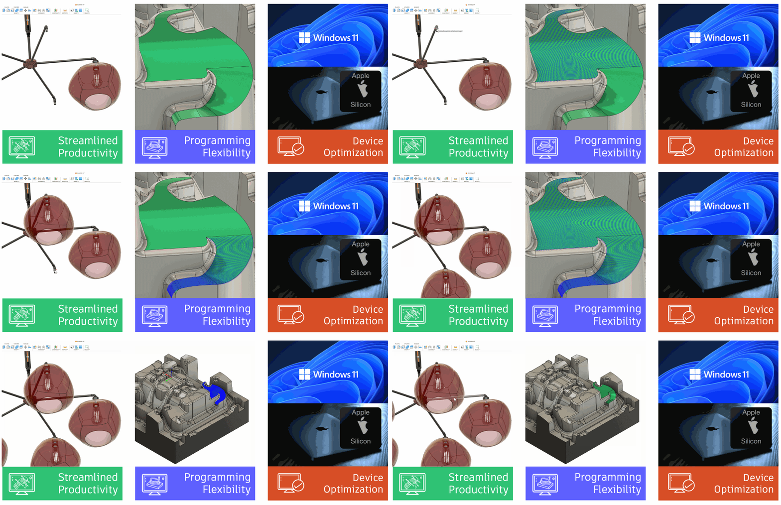
Want to learn more about all the updates coming to Fusion 360 this July? Join us on Thursday, August 3, 2023 for a LIVE webinar where we’ll dive into improvements around flexibility, control, and programming efficiency, show off some tips & tricks, and open up the floor for LIVE Q&A.
We have 2 sessions running for you to choose from, both identical in content, just at separate times. Click the links below to sign up. Looking forward to seeing you there! `
Register for 9am PDT | 12pm EST | 5pm BST
Register for 10:00am BST | 11:00am CEST | 2:30pm IST
Better Native Support for Apple Computers
Fusion 360 now runs natively on Apple Silicon
For all you Mac users out there we are excited to announce that Fusion 360 is now natively supported on Apple Silicon! When you launch Fusion 360 after this update, the software will automatically recognize whether your machine has an Intel chipset or an Apple Silicon chipset. If you are running Fusion 360 on a M1 or M2 processor, Fusion 360 will automatically run natively on that chipset without Rosetta 2.
Through our testing as well as feedback from our Insiders, we’ve seen noticeable improvements in stability, compute performance and battery life/usage. When it comes to compute speeds, modeling and assembly modeling tasks are generally 30% faster on Silicon compared to running on Intel /Rosetta 2. Local Rendering also saw a noticeable boost in speed, enabling you to achieve a finished render faster than ever before. The other major benefit here is battery life; Fusion 360 now consumes almost 50% less power running on Apple Silicon.
We anticipate that you may have more questions, so we encourage you to check out our FAQ article.
Native macOS trackpad engine for gesture processing
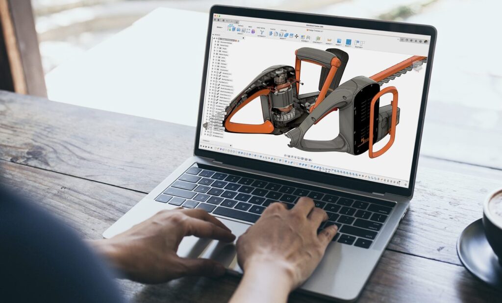
From its initial release, Fusion 360 used a custom trackpad engine to process canvas gestures on macOS. Since that time, the native trackpad driver available within macOS has matured tremendously and is more than capable of powering Fusion 360’s gesture-based navigation.
This release graduates our macOS Native Trackpad driver support out of preview, into full release. The result should be a more-stable canvas navigation experience that consistently registers pan, zoom, and orbit commands. A special thanks to user Pravdomil for your help and Native Trackpad add-in proof-of-concept!
Note: If you previously had the Native Trackpad Gestures add-in installed for Fusion 360, this will be disabled automatically after update to prevent a driver conflict.
High DPI Scaling support on Windows
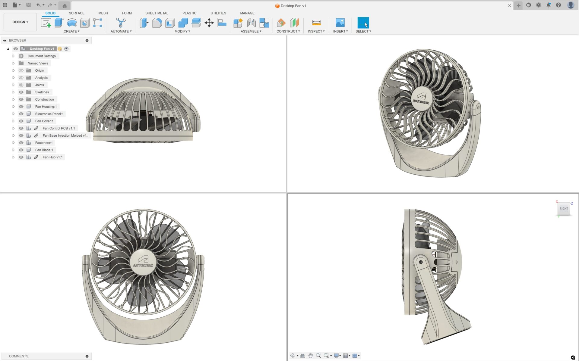
The Fusion 360 application now supports per-monitor DPI awareness on Windows out-of-the-box, bringing support up to par with our macOS client. Users running Fusion at greater _than 100% DPI will now be greeted with crisp fonts, icons, and canvas graphics – no more pixilation. Whether you’re scaling your monitor to 175, 250, or 325% or anywhere in between, Fusion 360’s will now look crisp and detailed instead of pixelated and blurry. This feature is enabled automatically when Windows is set to a display scale factor of 125% or greater. If needed, this option can be temporarily disabled under Preview Features within Fusion 360’s Preferences.
Note: High resolution canvas graphics may stress the performance capabilities of legacy graphics hardware at higher display resolutions. Users can disable high resolution graphics and related settings within Fusion 360’s Preferences under the Graphics and Display sections.
Online browser access now available to more subscribers
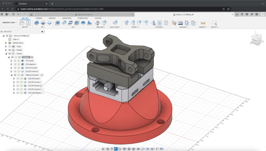
Fusion 360 commercial subscribers now have access to an online version of Fusion 360 which can be accessed through a web browser. This is another entry point into Fusion 360 that is provided free of charge to commercial subscribers to enable access from any device via a browser. The online version is provided in English-only and API’s are not enabled.
Browser access is available to:
Browser access enables flexible, “on-the-go” use of Fusion 360 which provides benefits such as easy collaboration, faster design iteration, and reduced system requirements as no local install is required.
For more information and to access instructions click here.
Improved File Access and Search
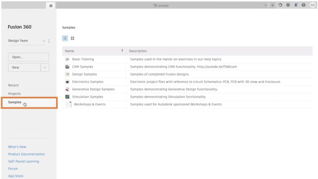
Sample files in Home Tab
Accessing samples is a breeze through the newly added Sample tab in Home. Easily navigate to the desired files and open them directly in the Fusion 360 canvas. Experience seamless sample file exploration and unleash your creativity in Fusion 360 like never before!
More characters visible in local file export path
The File dialog used for commands like Save and Export no longer prematurely truncates directory paths with ellipsis and will make use of the full available dialog width.
Performance is a key area of focus for us, evident of some of the improvements we’ve made over the past few product updates. This update continues to improve on the usability and modeling performance of Fusion 360, specifically around large assembly and drawing workflows. Here are the highlights:
Usability:
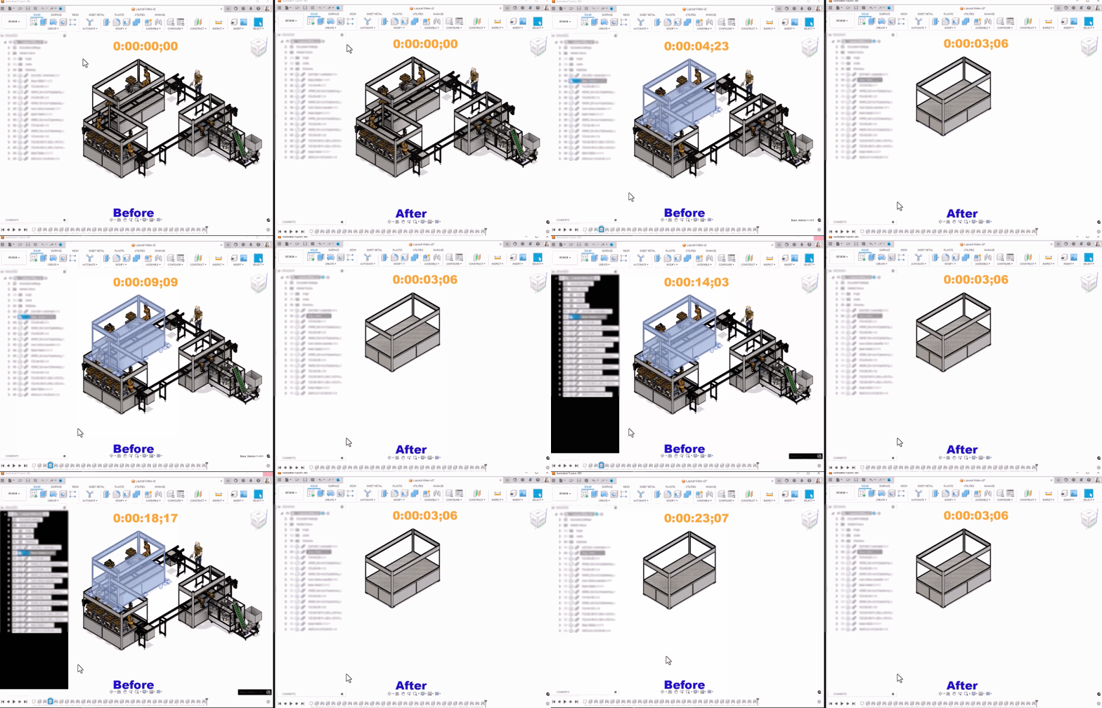
Assembly:
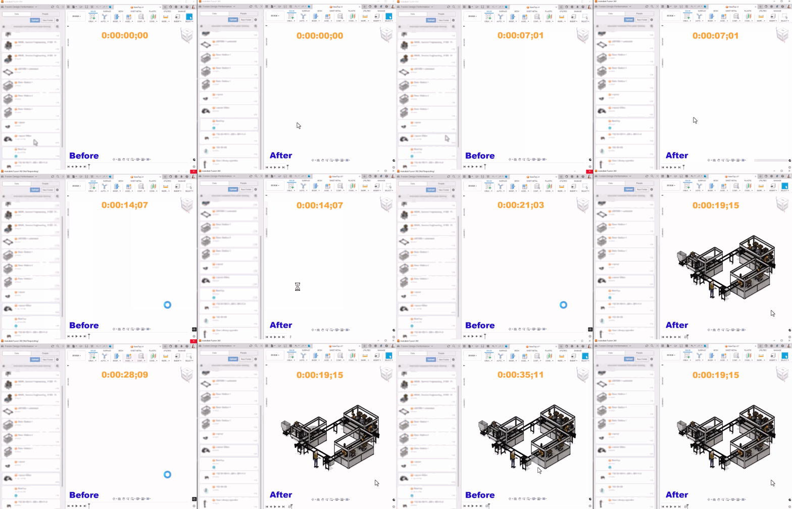
Drawing:
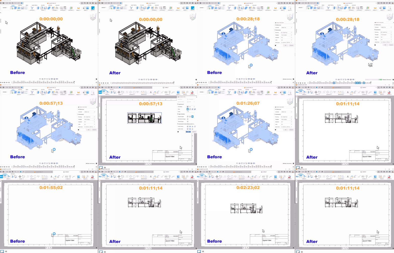
Modeling:
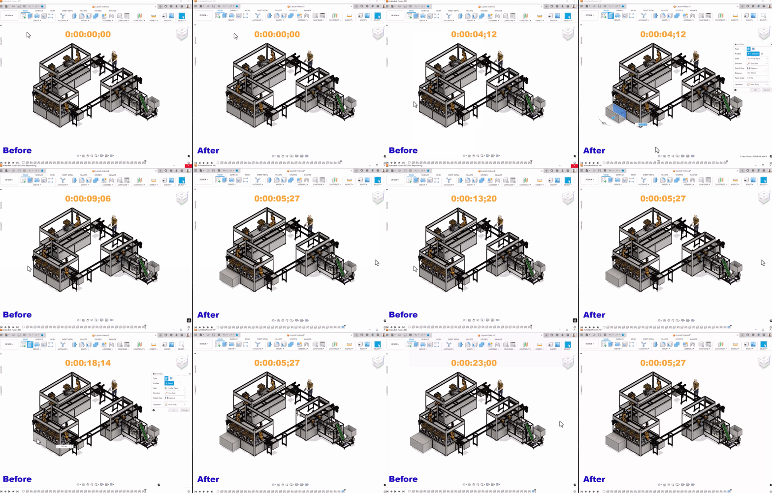
New Duplicate With Joints
Design>Assemble>Duplicate with Joints
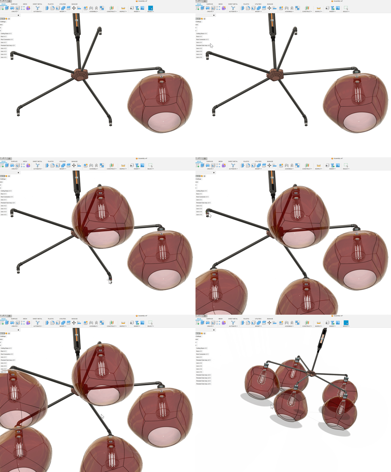
Many of you have asked for this, and we’re glad to say that it’s finally here. The new ‘Duplicate with Joints’ command, located under the ‘Assemble’ section, now allows you to duplicate a component or subassembly that has joints associated with it and quickly joint it in one or many additional locations. This is a massive workflow efficiency improvement and should help you speed up the task of copying and jointing of components.
Note: Standard copy command does not copy joints, and Captured Positions will not be duplicated.
Complex Surface Emboss

It is now possible to create embossed features on non-developable faces, such as spheres, toroids, and doubly-curved faces.
Better Mesh Creation for Volumetric lattice bodies (Product Design Extension)
Previously, a mesh would be made of one face and was not very workable for downstream manufacturing. Now after you create a mesh body from a volumetric lattice body, the newly created mesh bodies are made up of multiple face groups based on the faces that made up the original solid body. You can now select those individual faces as inputs for adding support structures in additive manufacturing setups. This simple improvement will be very useful for adding support material in 3D printing.
New Default Documents Preference
Preference > Default document preference > Electronics Design
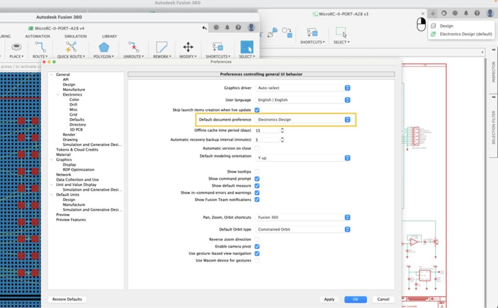
In this update, you will now have the option to customize your Default Document Preference to either Design or Electronic Design. Once set, Fusion 360 will automatically load the Preferred Document upon launching. By selecting Electronic Design as your preference, Fusion 360 will launch directly in the Electronics Workspace, eliminating the need for multiple steps typically required to access it from the Design Workspace.
Furthermore, when creating a new document, the Fusion 360 will open to your Document Preference, providing a streamlined experience. During document creation, you can access the context menu and select between Mechanical Design and Electronic Design options. The hotkey Ctrl/CMD+N has also been modified to align with the newly chosen document preference.
Display Component Origin As Cross for dxf.ulp
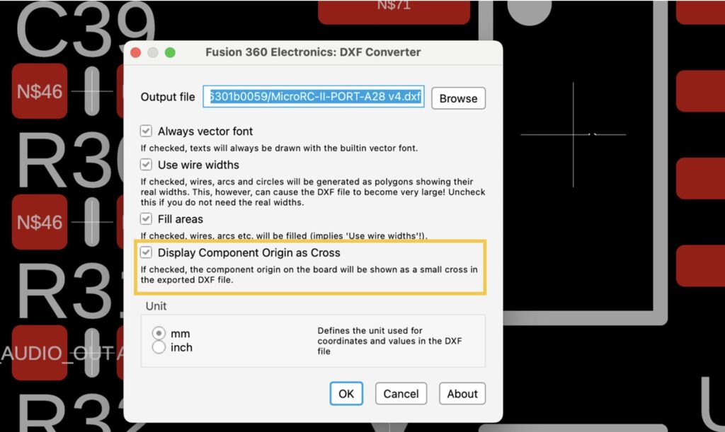
You now have the option of including the origin of the components to the DXF output, represented by a small crosshair. This will give you a more accurate representation of the design when importing the resulting DXF file into other applications.
Support for parts without 3D Models
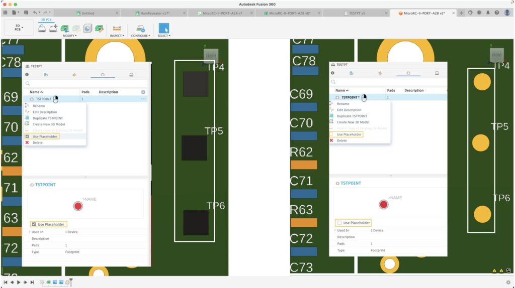
Sometimes you want to make footprints that don’t require having a 3d model (for example, test points). In this update, you can specify if the footprint should use a placeholder shape, such as a 3D model or the default box. If “Use Placeholder” is deselected in the Fusion 360 library footprint editor generating the 3D model of the part will not have 3D model representation. Previously, achieving this level of control necessitated a series of intricate steps in the library package editor. Introducing this new feature in the library editor streamlines the process of creating parts, particularly those that do not require a 3D model or may undergo future mapping without needing the default box to be displayed. This enhancement significantly enhances the overall design experience.
New Swap (Replace) library
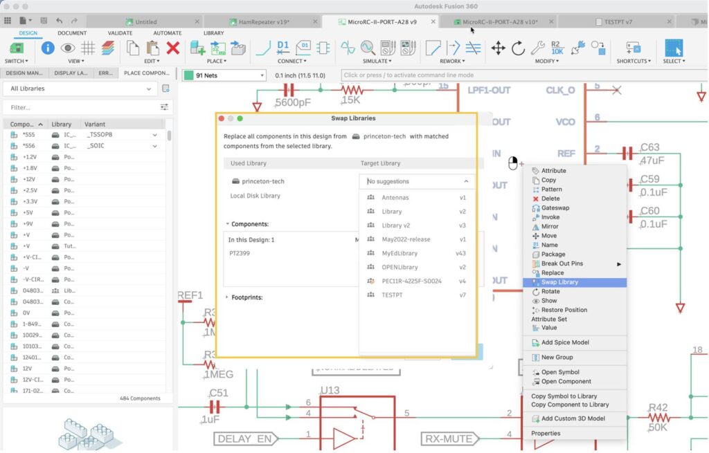
The process of importing EAGLE design and library files into Fusion 360 has previously presented challenges, potentially leading to losing the link between the design and the library. Similarly, the link can be severed when design files are shared with you through exported designs. Addressing this concern, we are introducing a new workflow option called “Swap library”. This valuable feature empowers you to associate your designs and libraries with minimal effort swiftly. By simply selecting the option within the design file or library, the system will search among the currently active libraries and propose the most suitable matches for the swap. This streamlined functionality significantly expedites updating imported designs, ultimately enhancing efficiency in working with your designs.
Create new windows with Multi-Window/Multi-Monitor Setups
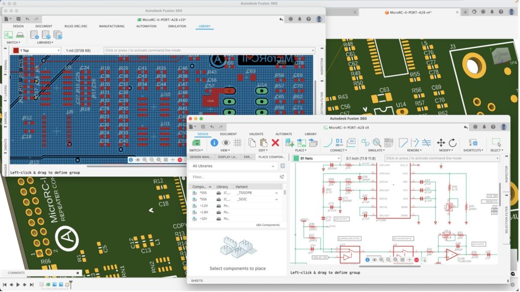
Previously when you create a new window by pulling off the document tab, and if you did this on a secondary monitor, then the new window would constantly appear on the primary monitor, even though the application was on the secondary. This was quite frustrating, which is why this enhancement ensures that the new window is created on the same monitor where the application was and where it was dragged off from.
Streamlined DRC Panel
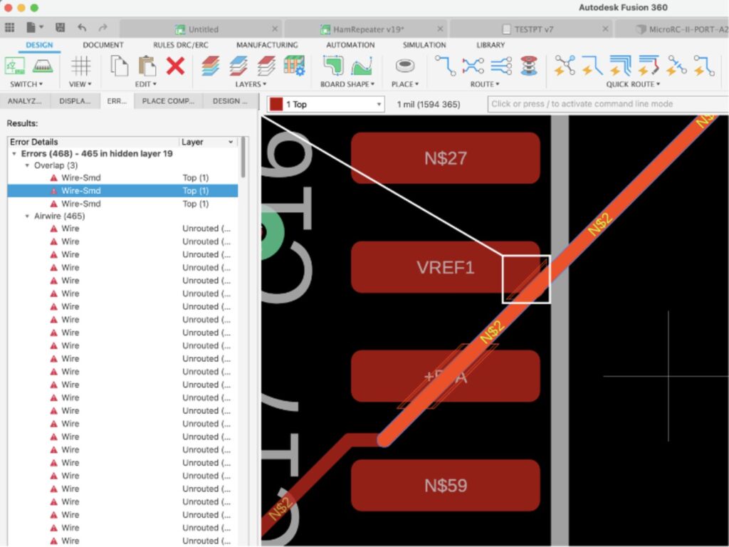
When working on the schematic, it is common practice to run your Electrical Rule Checks (ERC) to make sure that synchronicity between your PCB and schematic remains consistent; it also helps to detect possible undesired connections errors on your design, such as mixing digital and power connection to a single node. The new ERC panel will list warnings indicating if connections such as power and non-power labeled nets are connecting.
The DRC panel is convenient because you can see and address errors not meeting your DRC requirements in real time. Highlighting any of the items on the list will provide the location of the offense. Streamlining DRC into a panel makes it easier to have it always assessable that way, you can address these errors and warning early in the design cycle.
Support Net Name Autocomplete for Polygon
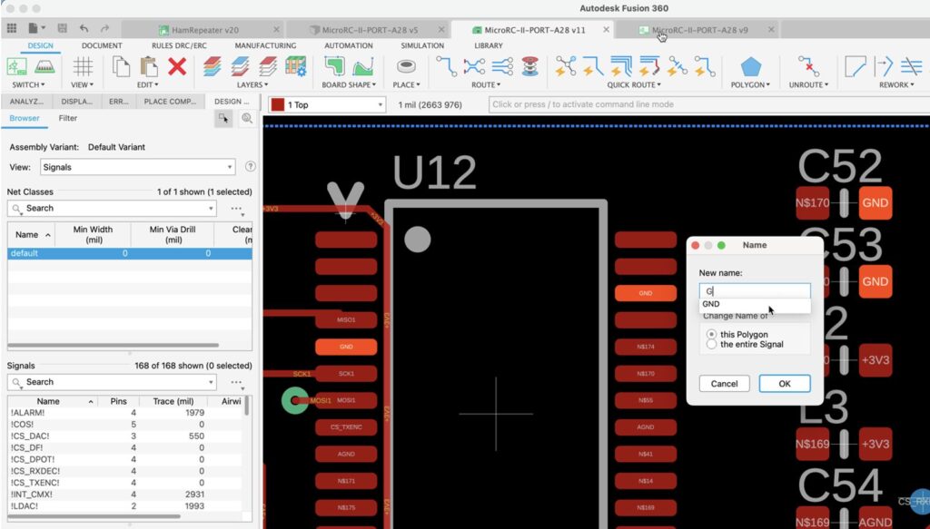
Polygon pours are crucial on a PCB as they help efficiently distribute power and ground planes, minimizing voltage drops and noise. Additionally, they aid in thermal management by providing a larger copper area for heat dissipation, enhancing the overall performance and reliability of the electronic circuitry. In this update, we have made it much easier to name your polygons since it will now support Auto Complete.
Enhanced Inertia Relief in Remove Rigid Body Modes (Public Preview)

Inertial relief can now be used alongside a much wider range of manufacturing methods, such as Unrestricted, Additive, 2 axis cutting, 2.5 axis milling, 3 axis milling and 5 axis milling. To try this, make sure that you have the “Experimental Generative Solvers and Features” public preview turned on.
Note: Die casting manufacturing method is not supported together with Inertia relief.
Improved Right-Click Behavior
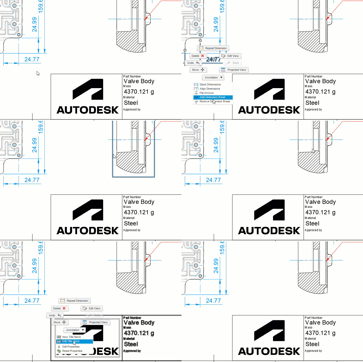
This is one of those day-to-day features that you may not notice but is guaranteed to reduce clicks and improve your productivity. Previously, you had to first select an object on a drawing, before you could right-click on it. We didn’t like this either, so we’ve fixed it. With this release, you can just right-click on views, dimensions, title blocks etc. and edit them as expected. Top Tip, we added the ability to open the model directly from a drawing view last September, this should be even easier now.
Flip Dimension Arrows
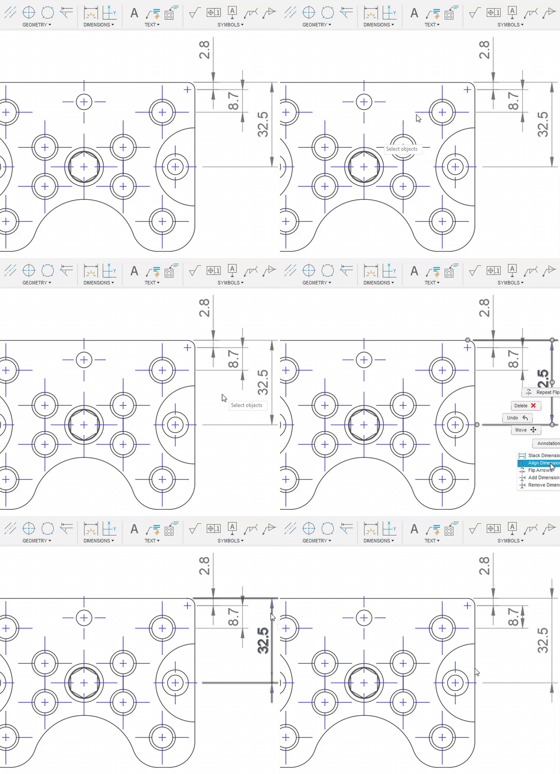
This one has been on the roadmap for a while! If you’ve ever wanted to flip an arrow position on an awkward dimension, this is the feature for you. Simply right-click on a dimension and choose “Flip Arrows” then pick the arrows to flip. You can also find this feature under the Dimension dropdown on the toolbar.
Learn how to Flip Dimension Arrows.
Properties and Parameters Anywhere
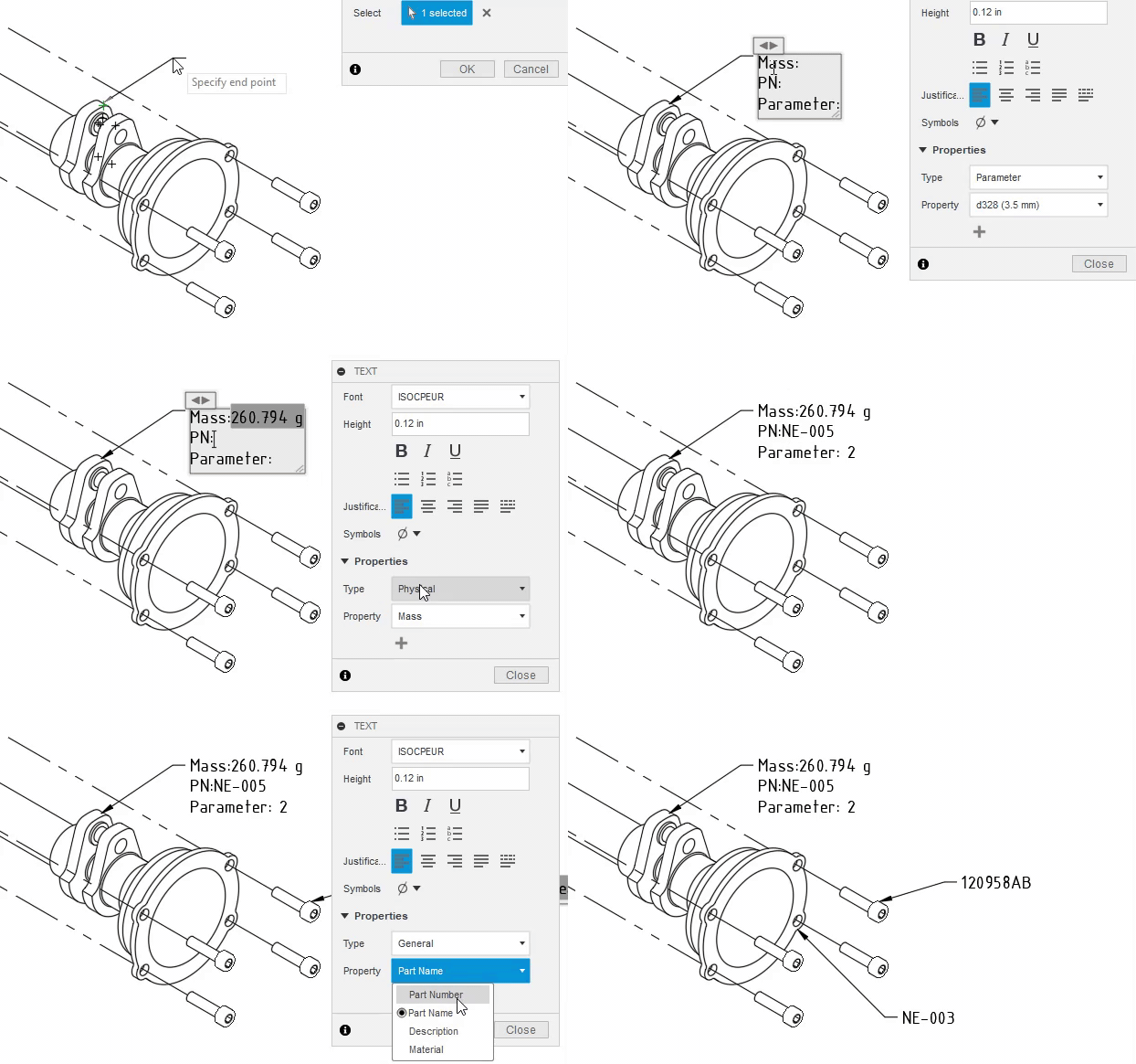
You can now place Model Properties and Model Parameters into ANY text field on your drawing. When creating or editing Leaders, Text, Custom Tables or Dimensions, it’s now easy to add model properties and parameter information to your text elements on a drawing. Simply choose the category, select the property, hit the + icon, and you’re all set.
Learn more about Properties and Parameters Anywhere.
Improve View Quality for Shaded Views
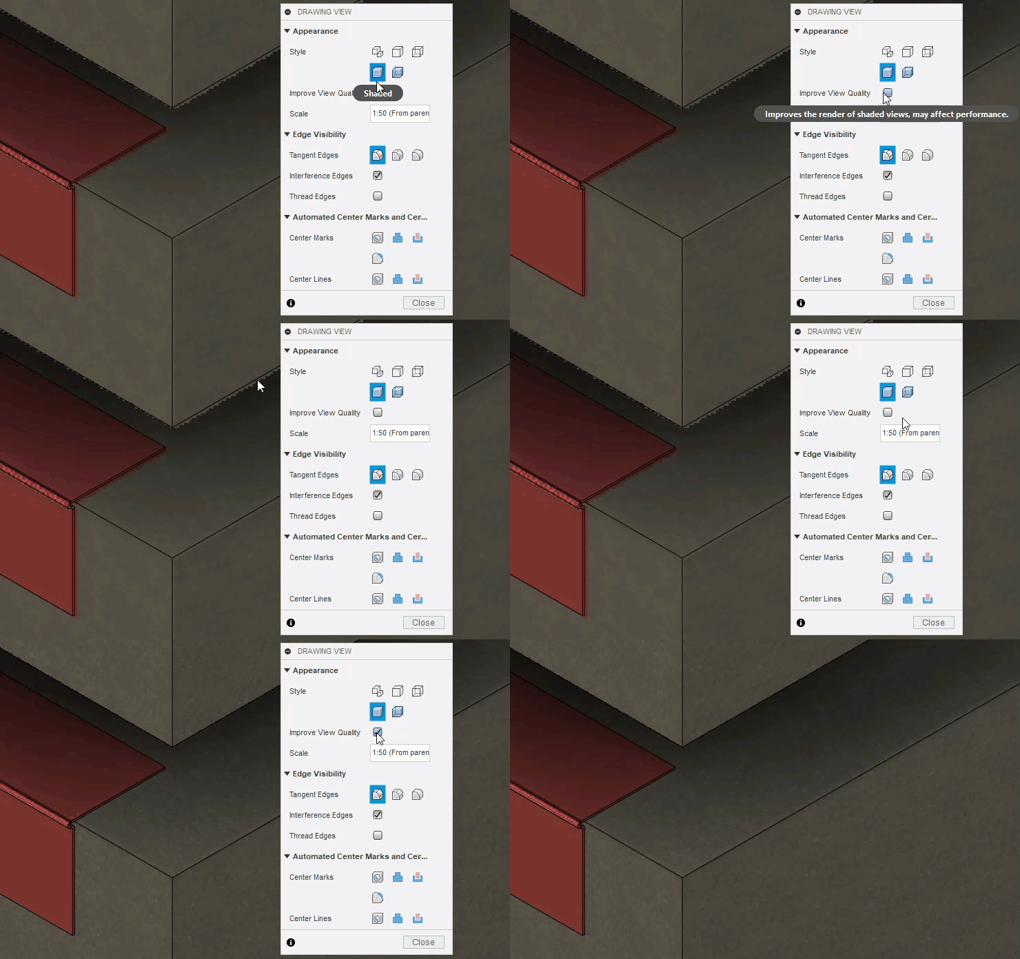
Models with a mix of long thin and thick parts can have shaded views that are a bit tessellated when zooming in. An example could be a thin sheet metal component bolted to a thick concrete slab. This new feature improves the appearance of these shaded. The shaded view is sharper, but the file size increases, and may result in a slightly slower performance.
Learn more about Improved View Quality for Shaded Views.
Displaced Center of Mass for Deformed bodies
Simulation> Results> Inspect> Center of Mass
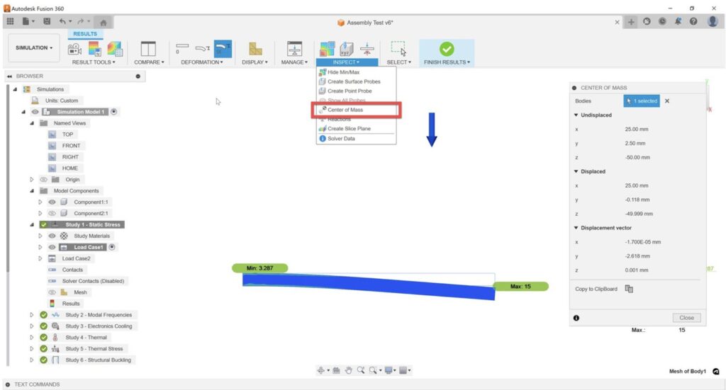
You can now get the information on the Center of Mass of a deflected body from their simulation results. The feature will give you information on the un-displaced Center of Mass, displaced Center of Mass and the Displacement vector of the Center of Mass of the selected body. Additionally, you can select multiple bodies in which case, the combined Center of Mass values will be provided. This feature is now available in the Linear Static Stress, Thermal Stress, Non-linear Static Stress, Quasi-static Event Simulation and Dynamic Event Simulation study types.
Align Extensions for Geometry Features
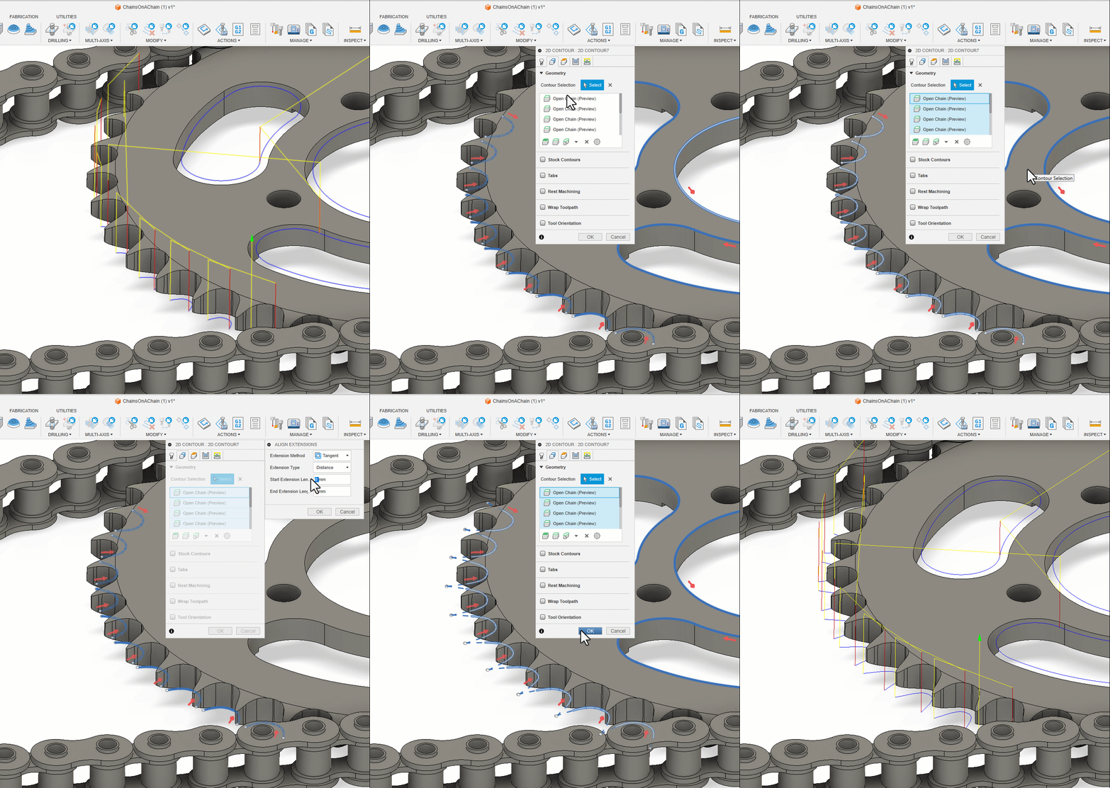
Earlier this year, Toolpath extensions were moved from the individual toolpaths to the Geometry Selections – this gave the advantage that the toolpath preview could be more accurate because it included the toolpath extension as a preview. The downside of this was that you had to edit or define the extension values on a per selection basis. This has caused a significant problem for small percentage of you. Based on lots of feedback, we’ve improved this experience so that you can change multiple extension values at the same time. The GIF above shows how you can highlight all open contours with a simple click and then globally modify them to have a user defined start and/or extension.
Allow Inside to Outside for Face Turning
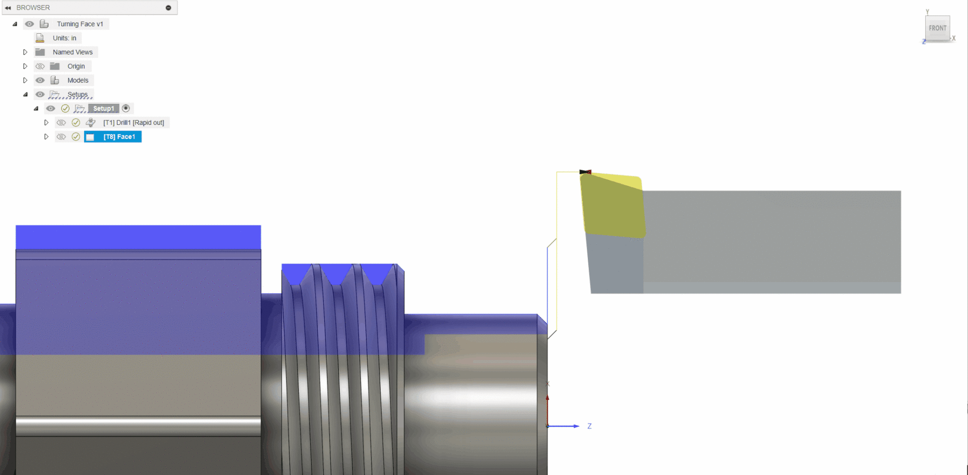
A feature that has been requested by many of you for a while is the ability to face a part starting from the smallest diameter, working its way out to the biggest. We’re glad to say that now, this is a simple option you can access from the passes tab. This type of toolpath is commonly required when you are machining tubes internally with a boring bar and additionally also required to face off the part with the same tool in an upward direction which helps to control the size of the burr. A more consistent burr results in better quality surface finish and an improved tool life.
Machine Groove Undercuts for Profile Finishing
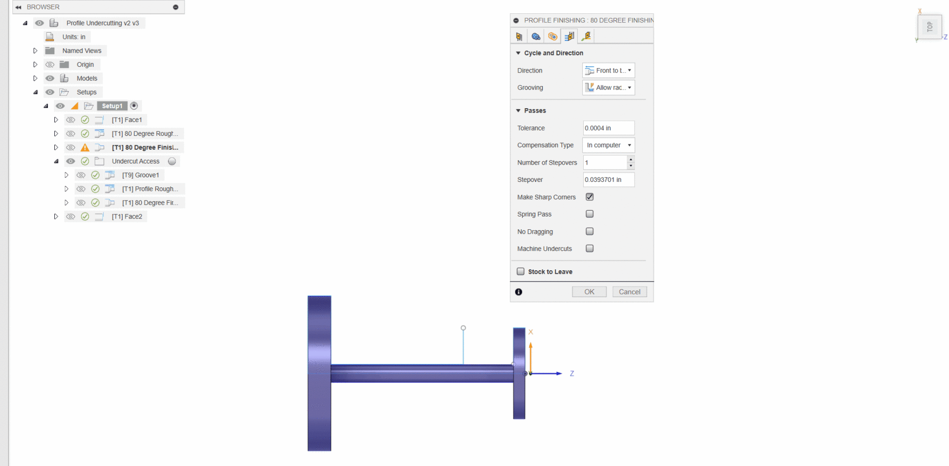
The moment many of you have been waiting for is here, as of this update you can now machine groove undercuts in Turning Profile Finishing! With machine undercuts turned on, now the tool will move vertically into the undercut region to allow the finish machining of the undercut diameter. This allows a general tool to be used to finish an undercut and in doing so will produce a more efficient material removal, less requirement on subsequent finishing operations to explicitly finish undercut areas.
Back Wall Collision Checking for Undercuts for Groove Finishing
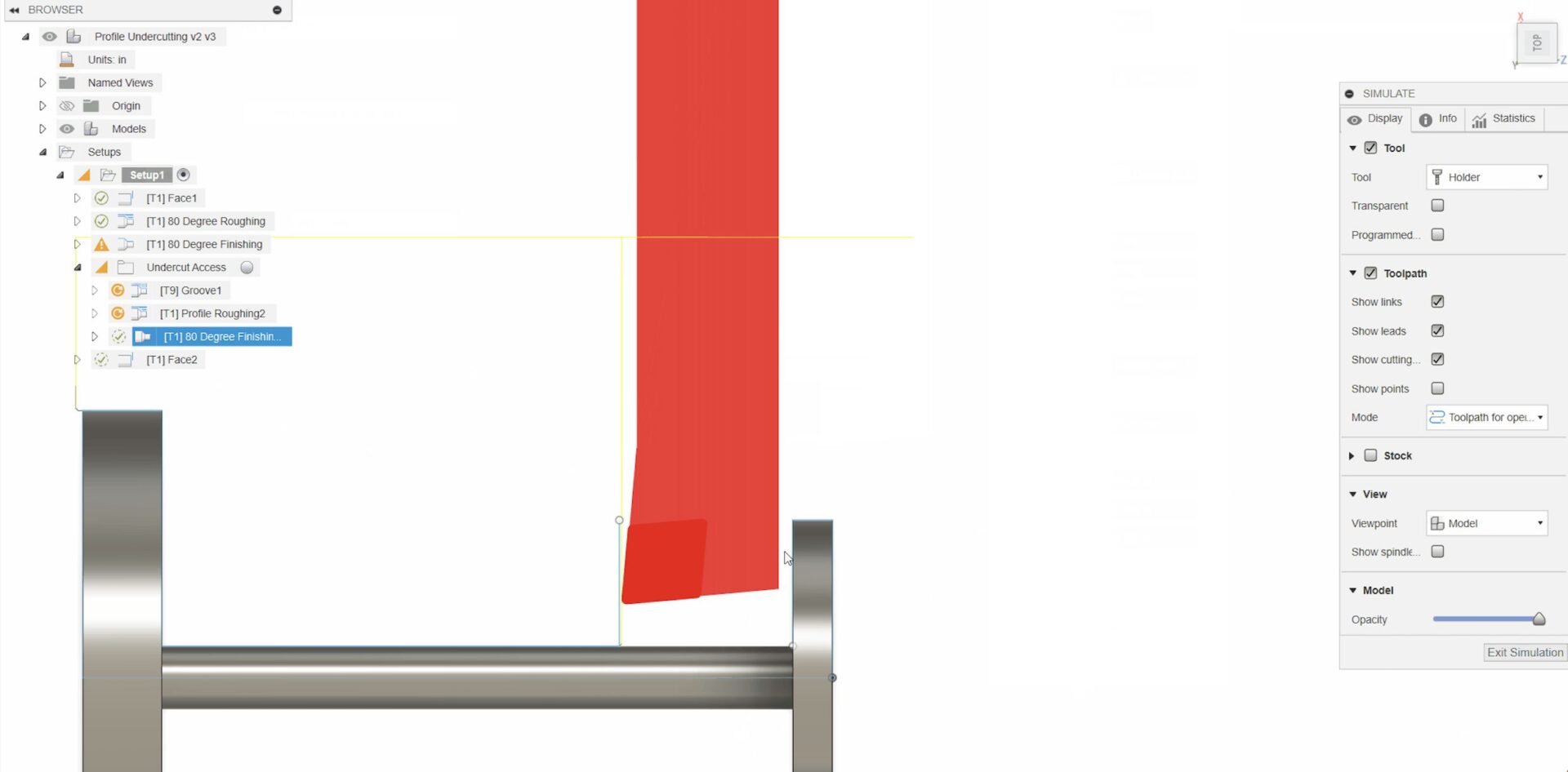
Notice how there is a slight gap between the back of the tool and the wall of the part. That’s because we have also added the ability to set a clearance value for either the back of the holder or back of the insert. You may select the one you prefer depending on the tool being used and this will result in the holder or insert maintaining that set distance from the vertical walls for external work or bosses for internal work so that we minimize potential collisions and maximize the area of undercut being machined.
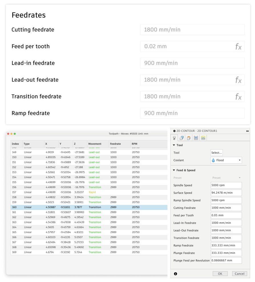
Transition feedrates have now been added to milling tools, to allow for enhanced optimization of toolpaths. You can set this new feedrate option for transition moves in the tool library, per tool and preset, and/or in the toolpath itself on the tool tab.
The default will be associatively linked to the cutting feedrate, but this of course can be customized by using a simple numeric value or formula.
For verification, you can visualize this new feedrate in both the toolpath simulation, as well as in the ‘Show Toopath Data’ dialog.

Blend is a finishing strategy for machining the shallower regions of a part between selected contours with a constant cutting direction. It’s a very versatile strategy . It supports undercut machining in 3axis only with applicable tools such as lollipop, disc, barrel tools and dovetail cutters.
A new way to define Blend toolpaths is now available. The new method produces toolpaths that avoid fragmentation on complex geometries, enabling them to be machined to a higher surface finish more easily.
To select the new method choose the ‘From tip of tool’ option for Stepover Calculation on the Passes page. The pre-existing method can be selected by choosing ‘On surface’.
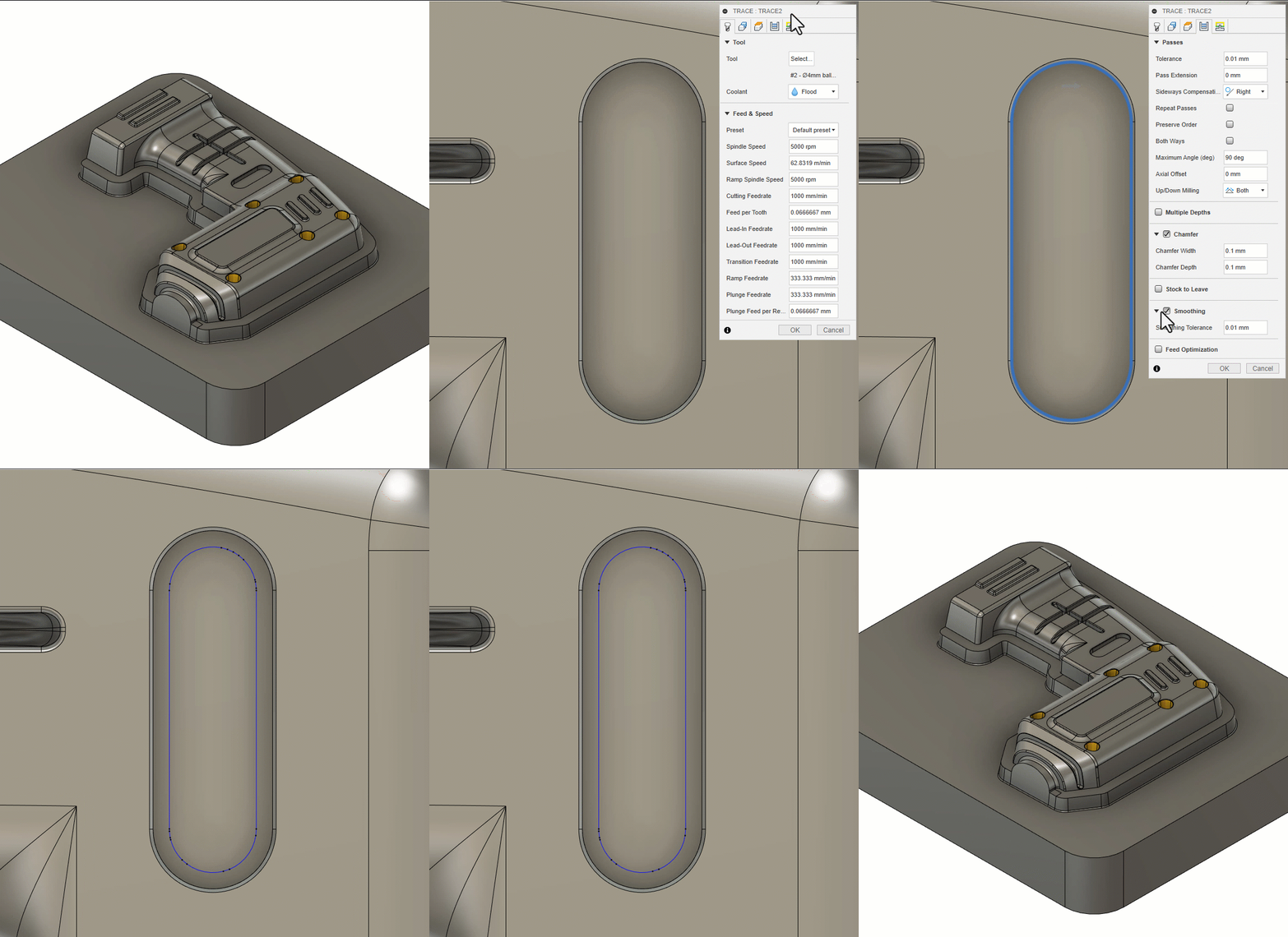
The smoothing option in strategies like Trace, Flow and Flow Preview can now apply arc fitting. This is particularly suited to older generation controllers whom prefer arcs over linearized points. We continue to see jittery motion in controllers that don’t like a lot of points so enabling smoothing will effectively remove some of those points in favor of arcs but only where it can still maintain toolpath tolerance.
Trace and Flow are already fully released however if you want to use the Flow Preview toolpath, then you’ll need to turn on the “Enhanced Flow Strategy” public preview.
Extended 5 axis (to/from point and curve) options
Blend, Flow and Flow Preview all had the option to use Lead/Lean primary tool axis options with all milling tool types. What we have done is preserve this original capability, but in addition to preserving this lead/lean capability, we have added the usual Extended 5 axis (to/from point and curve) options, however these options are restricted to spherical tools only.
WCS Z-axis support
Blend/Flow and Flow Preview previously only supported Min/Max tilt options but those limits were always defined relative to the toolpath orientation Z-axis. Now, they can also be expressed relative to the WCS Z-axis, and where applicable, spherical and non-spherical tools are supported here.
Automatic Collision Avoidance for Multi-axis Contour
Multi-axis Contour can now use Automatic Collision Avoidance (When the tool axis is set to vertical) as the Primary Tool axis. While Collision Avoidance options (TO/FROM Point/Curve) are also available to the toolpath, the limitation is that it can only be used with spherical tools. Where Lead and Lean is concerned, spherical and non-spherical tools are supported. You can also output a 3-axis specific toolpath for Multi-axis Contour. This essentially limits the multi-axis toolpath to 3-axis only.

Geodesic Strategy is now in Extension Preview! The number one benefit of this toolpath is the ability to machine undercuts. Geodesic it’s no secret comes from the fruits of our relationship with ModuleWorks. Geodesic basically creates its toolpaths in either a Scallop or Blend style strategy, but unlike regular Scallop or Blend, the Geodesic Scallop can offset from a variety of user defined open or closed curves. Native Fusion Scallop always offsets from the closed containment curves. The Geodesic Blend can blend between user defined curves (not restricted to face edges).
The Geodesic toolpath can automatically add additional offset/overlaps to the user defined curves, so when machining a fillet, instead of starting exactly on the edge of the fillet, you may want to start a few mm’s before the edge, and blend the toolpath into the fillets edge.
Note: Geodesic can also machine in 3 axis in Core Fusion), 4 and 5 axis for those who have the Machining Extension.
Learn more about how to set up a Geodesic toolpath.
We already have swarf today, so why are we introducing another Swarf toolpath called Advanced Swarf? The answer is simple: it has several advantages over the original Swarf.
To start, Advanced Swarf has greater flexibility for input geometry whether that’s contours or surfaces. Secondly, it can degouge the surface. Thirdly, it can auto synchronise between the top and bottom rails and gives a relatively large degree of flexibility about how you go about applying that synchronisation and therefor how it controls the tool axis. Lastly, Advanced Swarf toolpath is not restricted to only 5axis like the original swarf; it can do 3, 4 and 5 axis machining. 3 axis is very useful for vertical walls, 4 axis for wrapped features around things like cylinders (which you have been asking for a long time) and 5 axis for things like undercuts.
Learn more about how to set up an Advance Swarf Toolpath.
Looking for the latest post processors and machines updates? This July we released a ton of new updates and improvements to many of the open-source Post Processors and Machines we offer for free. Within this release you will find the addition of post processors for both Fagor Waterjet and LightBurn Laser Software, as well as improvements to generic post processors, milling post processors, and mill-turn post processors. Additionally, we added the Techman Robot User Guide, updated and improved our Workholding library, and improved functionality around the Autodesk CAM Post Processor engine.
To learn more check out the forum post here.
FFF Filament Diameter Input Now Included in Machine Definition
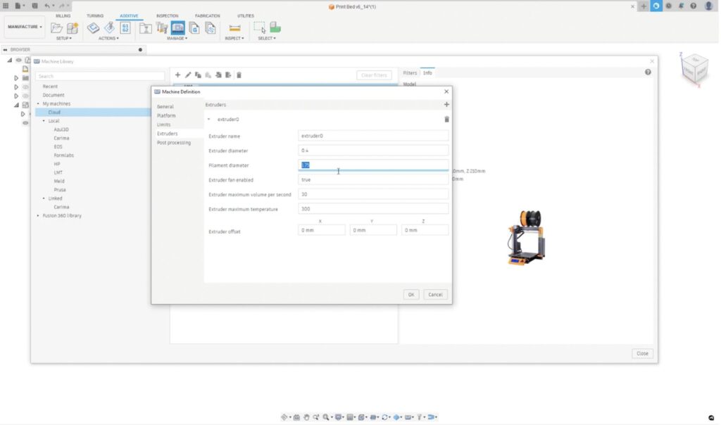
The ‘Filament Diameter’ setting from the FFF print settings, has been moved appropriately into the machine configuration. This was done as part of a clean-up on the print settings and improve the user-experience. Instead of having different print settings per filament diameter, we now simplify it to extruder drive type.
This change comes with the added benefit of allowing users to be able to specify a filament diameter per extruder if needed.
Unfortunately, this means that users might find that all previous FFF setups and non-Fusion 360 Library FFF machines, show an error when the toolpath is generated. There is a simple fix where users will need to manually update their ‘filament diameter’ setting in the machine configuration. To help you do this, we have created a helpful video here:
Note, this will only need to be done once per setup or FFF machine
Another improvement is around the machine visibility after the toolpath has been generated. We can now control the visibility of the platform from within the toolpath Simulation dialog.
FFF Energy Consumption Prediction Now Available For All Users
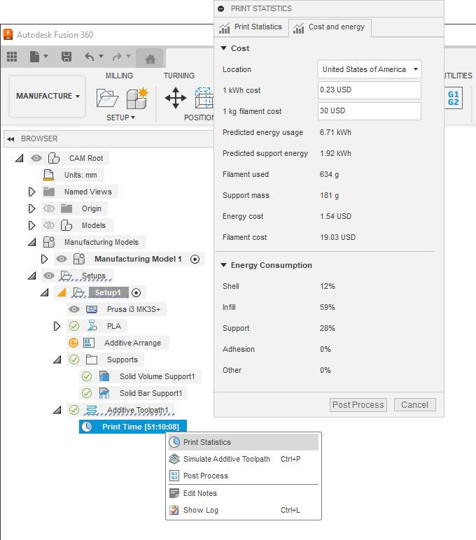
After creating an additive setup with an FFF 3D printer, and calculating your additive toolpaths, you can now see the energy and filament cost associated with that print within the Print statistic dialog, before pressing Print on your 3D printer.
Learn more about how to display print statistics.
Markforged Digital metal PX100 Binderjet 3d printer support
Fusion 360 + Additive build extension will be able to 2D and 3D arrange models within the PX100 build platform and slice the models and export them as a CLI file.
Mesh Bodies are now compatible
Additive Process Simulation users can now use mesh bodies in their simulation studies. This allows for the direct use of STL, 3MF, OBJ, and other mesh filetypes without having to convert into a solid body first.
Learn more about Process Simulation.
Create compensated native mesh bodies
Additive Process Simulation users can now generate a compensated native mesh body from their completed studies. The resulting parametric mesh body will be inserted back into the manufacturing model, with the corrective mesh morphing applied. This mesh body can then be used for a subsequent simulation, which can be used to make sure the compensation did not incur additional recoater hits or result in localized overheating.
Learn how to create a compensated mesh body.
Displacement Results can now be exported in a Color 3MF
After a successful Additive Process Simulation study, users can now export a color 3mf file. This records the predicted displacements to the mesh itself. Users can then import this back into the Mesh area of Fusion, or into any 3mf reader, to view the displacements on the mesh itself. Users can use their color 3mf compatible slicing software to print color 3mf files to have a physical, color coded polymer representation of the prediction distortion of their metal additive geometries.
Learn how to export a warped 3MF file.
Using the CAM API you can now generate an Automatic Orientation operation within an Additive Setup for a given component and apply a given orientation result outcome to the Component.
CAM Attributes can now be applied to operations and reused during the same session.
CAM API can now control the visibility of operations and folders
Additional geometry selection classes (sketch profile & pocket recognition) have been added to the CAM API to be used in operations which use parameters of the CADContours2DParameterValue type.
Get a sneak peek at what’s to come in the 2023 Fusion 360 Roadmap and an understanding of the “why” behind the features we’re investing in.
DISCLAIMER: Roadmaps are plans, not promises. We’re as excited as you to see new functionality make it into the products, but the development, releases, and timing of any features or functionality remain at our sole discretion. The projects mentioned in this roadmap are highlights and do not account for ongoing efforts like bug fixes, platform, and service maintenance. These roadmap updates should not be used to make purchasing decisions.
By clicking subscribe, I agree to receive the Fusion newsletter and acknowledge the Autodesk Privacy Statement.
Success!
May we collect and use your data?
Learn more about the Third Party Services we use and our Privacy Statement.May we collect and use your data to tailor your experience?
Explore the benefits of a customized experience by managing your privacy settings for this site or visit our Privacy Statement to learn more about your options.