Elevate your design and manufacturing processes with Autodesk Fusion
November 2023 Minor Update
(v.2.0.17954) – November 30, 2023
General:
- We fixed an issue where Projects in the Home Tab were not being displayed for New Accounts within a new hub.
- We fixed an issue where feedback on selected profiles in the graphics window was not operating as expected.
Design:
- We fixed an issue where the upload of Configured Designs would fail for Personal entitlement users.
- We fixed an issue within the Sketch environment where the green tick used to indicate the end of a line would no longer dynamically update and would appear in strange places.
- We fixed an issue causing the Sketch origin to appear in an unexpected location.
Drawings:
- We fixed an issue where upon the creation of a new drawing, or opening of a drawing, the drawing workspace viewport would flip upside down.
- We fixed an issue in Manage Extension where the punch out button within managed drawings led to incorrect corresponding pages.
Electronics:
- We fixed an issue within Fusion Electronics causing scrolling on a Mac touchpad to not work as expected.
- We updated Autodesk-supplied libraries so that they use new layer names and don’t use deleted layers.
- We fixed an issue causing an unexpected Min Width DRC error to appear.
Manufacturing:
- We fixed an issue causing the Tool library to crash when changing type to circle segment tool.
- We fixed an issue where 3D Adaptive “Rest Machining > Ignore Stock” produces the incorrect toolpath.
- We fixed an issue where reduced feed for turning threads with a grooving tool was not respecting depth settings.
- We fixed an issue where 2D Pocket fails to create toolpath
- We fixed an issue where Packaging was all renamed to the same name after loading a Nesting Preset.
- We fixed an issue where the Optional Features checkbox within the Manufacturing Preference page was not functioning as expected.
- We fixed an issue within the custom tool holder library where .hsmlib or .csv file types were unable to be properly exported.
(v.2.0.17721) – November 7, 2023
- When trying to use Fasteners in a Single user storage hub, the option is greyed out. This caused some confusion. There will now be a tooltip to notify you to transfer/switch to teams.
- We fixed an issue preventing users from inserting a DXF file after selecting a plane and a file while on Mac.
- We fixed an issue that occurred when trying to open a DXF file while on Mac.
- We fixed an issue where the Sketch Palette would disappear when switching between documents while editing a sketch.
- We fixed an issue where the “insert DWG browser” option was missing while editing the title block in Fusion 360 drawing.
- We fixed an issue where Machine Simulation would show too much compensation when using the Compensation Type: “Wear”.
- We fixed a crash issue that occurred when deleting hole recognition in the CAM workspace.
(v.2.0.17710) – October 30, 2023
Table of Contents
- November 2023 Minor Update
- October 2023 What’s New Highlights
- 10 Years of Designing Differently
- Usability
- Design
- Generative Design
- Drawings
- Electronics
- Manufacturing
- Simulation
- Data Management
- API and Add-Ins
- Customer Reported Fixes
- What’s Coming Next
NOTICE: Important OS support information after March 2024
After the March 2024 product update, Fusion 360 will no longer fully support macOS 11 Big sur.
In order for us to continue developing Fusion for the latest and greatest, we must stay current and end support for older OS versions. We recognize that this change may take you some time to adjust to. That’s why we are letting you know now, so you have plenty of time to update your OS to the latest version. We will continue to remind you here as well as in-product as we get closer to the March 2024 product update.
October 2023 What’s New Highlights
Design and Drawings:
- New Fastener Library
- New Ability to Copy a Historical Design Version with its Related Drawings
- New Internal Components Properties Configuration
- New Drawings Surface and Mesh Model Support
- New Drawings Custom Text Height Controls
- New Drawings Line Type Scale
Manufacturing:
- New Geodesic Toolpath Strategy (Machining Extension)
- Order optimization for 2D Pocket and 2D Adaptive contours
Electronics:
- New Mechanical Construction Geometry within 3D and 2D PCB
- Layer Naming Alignment
Additional Goodies:
- New Korean Community Fusion Forums
- New API Support
Live with the Experts: What’s New in the October 2023 Release
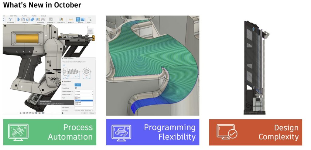
Want to learn more about all the updates coming to Fusion 360 this October? Join us on Thursday, November 9, 2023 for a LIVE webinar where we’ll dive into improvements around flexibility, control, and programming efficiency, show off some tips & tricks, and open up the floor for LIVE Q&A.
We have 2 sessions running for you to choose from, both identical in content, just at separate times. Looking forward to seeing you there! `
Register for 9am PST | 12pm EST | 5pm BST
Register for 10:00am BST | 11:00am CEST | 2:30pm IST
10 Years of Designing Differently
This year, 2023, Autodesk Fusion 360 is turning 10 years old. That’s 10 years of designing differently, 10 years of community-driven development, and 10 years of amazing products and content made possible by you. To celebrate, we have compiled a special 10-year anniversary video highlighting our content creator community, as well as a number of folks from the Fusion 360 team. Thank you for being with us for the past 10 years. You’re not done designing and making a better future, and neither are we. So, let’s keep doing this together—now and for the next 10 years.
Usability
New Autodesk Korean Community Forums

Exciting news for all members of the Fusion Korean Community, on October 4th the Fusion Korean Autodesk Forums went live! From now on we will be posting the Fusion 360 What’s New in the Korean language on our Fusion Korean Community Forum! Like with other language groups, you will be able to access these forums by following the forum link in the Community tab of Fusion 360 or by going directly to the forum page from within your browser. We can’t wait to see you there!
Note: you will only see the Korean What’s New link and Korean forum link if your language setting is set to Korean
Curious about what other international forums are available? Check out our international communities today:
– Deutsch
– Español
– Français
– Türkçe
– 中文 (Chinese)
– 日本語 (Japanese)
– 한국어 (Korean)
October Performance Improvements
Performance remains a primary focus for us, evident from the continuous improvements we’ve made over the past few product updates. This update further enhances the usability and assembly performance of Fusion 360.
Usability
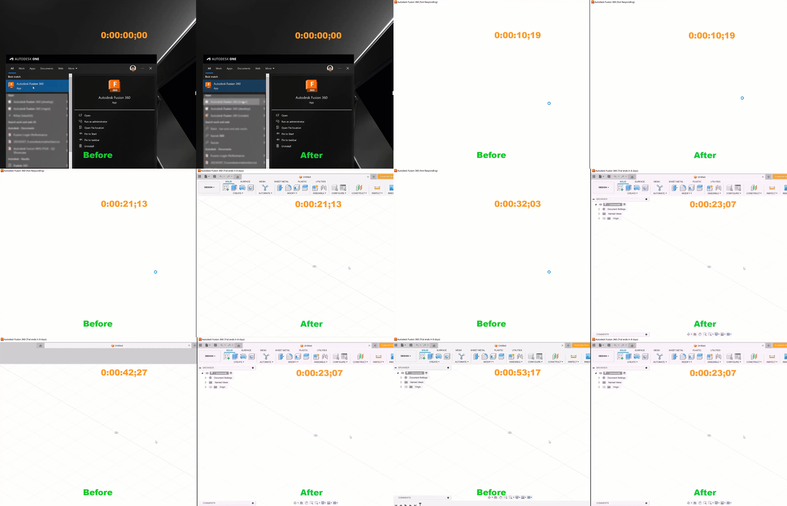
- The startup of Fusion demonstrates a remarkable time reduction up to 70-80%. The benefits are not just limited to start up, but for sign out / sign in workflows as well.
- The frame rate has been improved by up to 1.5x when orbiting with components in selection.
- Expanding the browser node of external component has been improved.
- Navigating a large number of files in Data Panel scrolls faster than before.
- Reduced lag when opening, navigating between, and closing multiple document tabs.
- Upload performance has been improved up to 20x.
- The performance of a nested external component visibility change has improved up to 2.4x.
Assembly
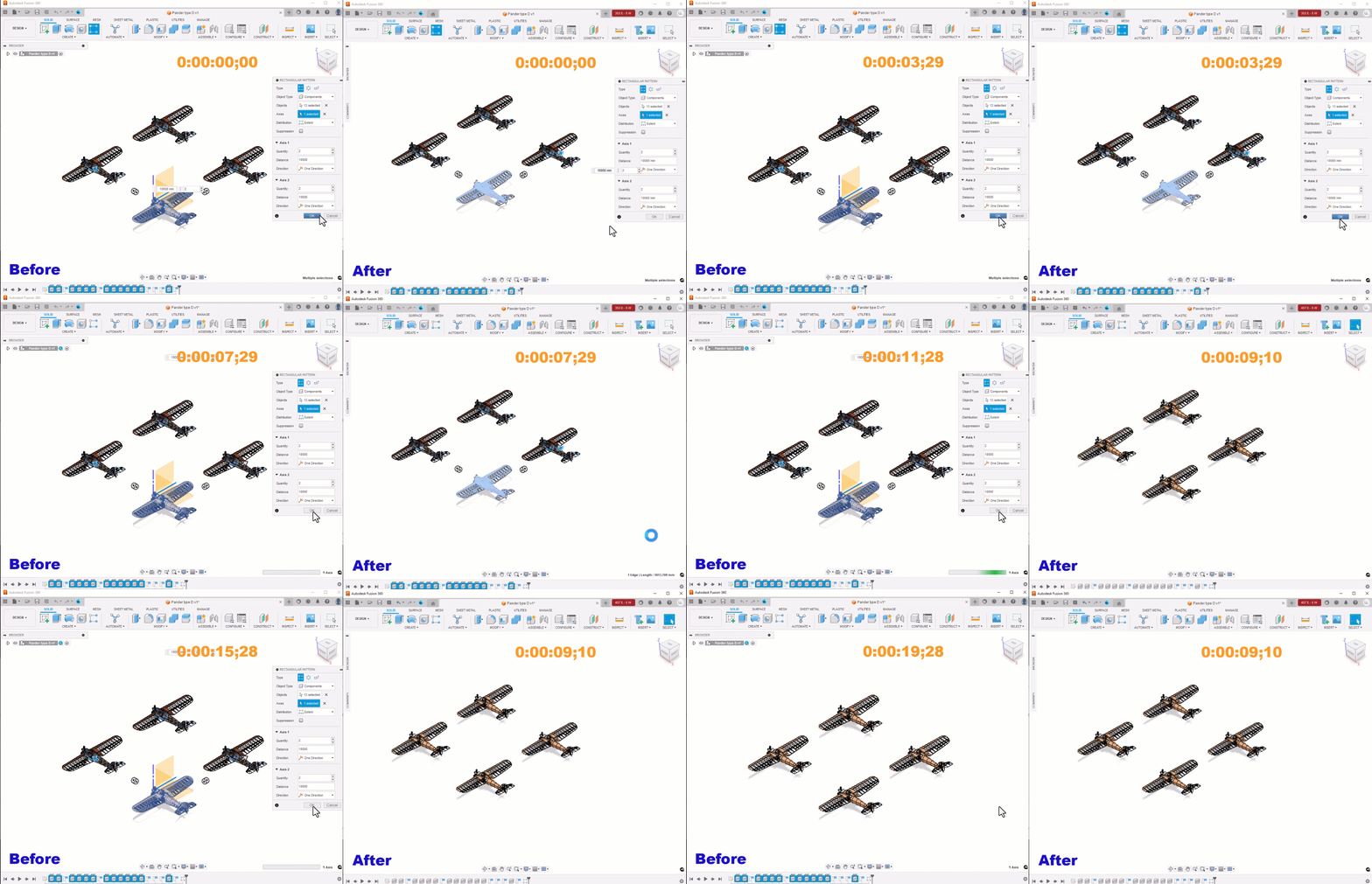
- Opening certain design files is now up to 193% faster than before.
- Consuming visibility, appearance, and isolating changes from external components in large assemblies has significantly improved.
- The performance of finish Edit in place for large assemblies has been enhanced to within 3 seconds.
- Fusion is now more responsive when editing Joint by selecting specific Mesh component in complex assemblies.
- The performance of Copy & Paste / Pattern / Break Link external components in large assemblies has dramatically improved.
Design
New Fasteners Library
There’s now a new Fasteners icon in the Insert dropdown menu that will launch our new cloud library. There’s no need to install anything— just select the Fastener icon to access a vast library of nuts, bolts and washers. Start by typing in your key search criteria, enabling filters and choosing industry standards to find what you are looking for.
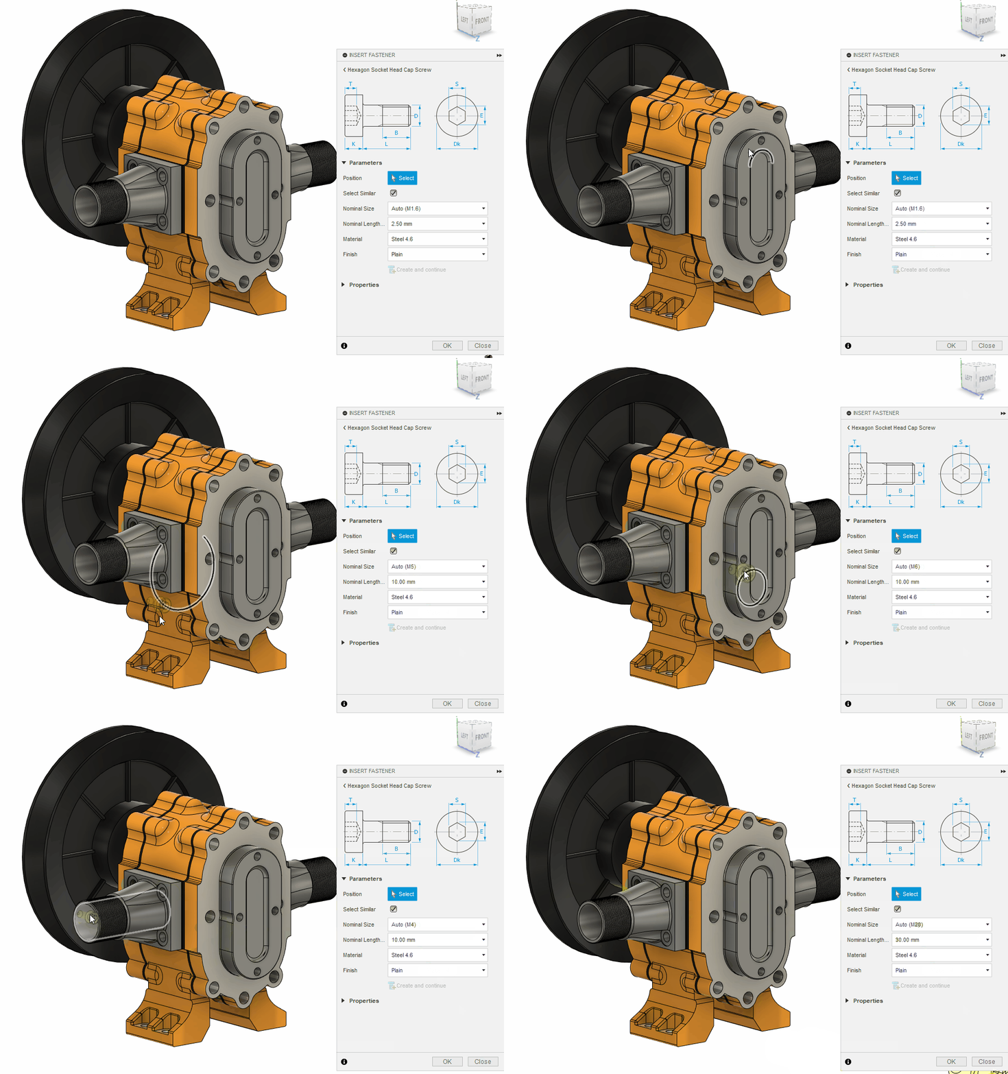
Once you zero in on the fastener you want to insert into your design, you can select multiple holes or let the tool automatically fill similar size holes on your part.
Should you ever need to change the size of a fastener, you can edit one or more fasteners as needed. When creating drawings, you will see the Bill of Material (BOM) populated with the description, part number, and quantities represented correctly. This enables you to easily get an idea of the type and quantity of fasteners in your design.
Learn more about the Fasteners Library.
Copy a Historical Design Version with its Related Drawings

We recently released the ability to copy a design and its related drawings. Since then, many of you have requested the ability to copy a specific historical version of a design and its related drawings. We listened and are happy to announce that ability is now here! As of this release designers will be able to select a previous version of a design in the data panel and copy the design with the option to include drawings.
Learn how to copy designs.
Reference Driven Dimension Outside the Current Sketch
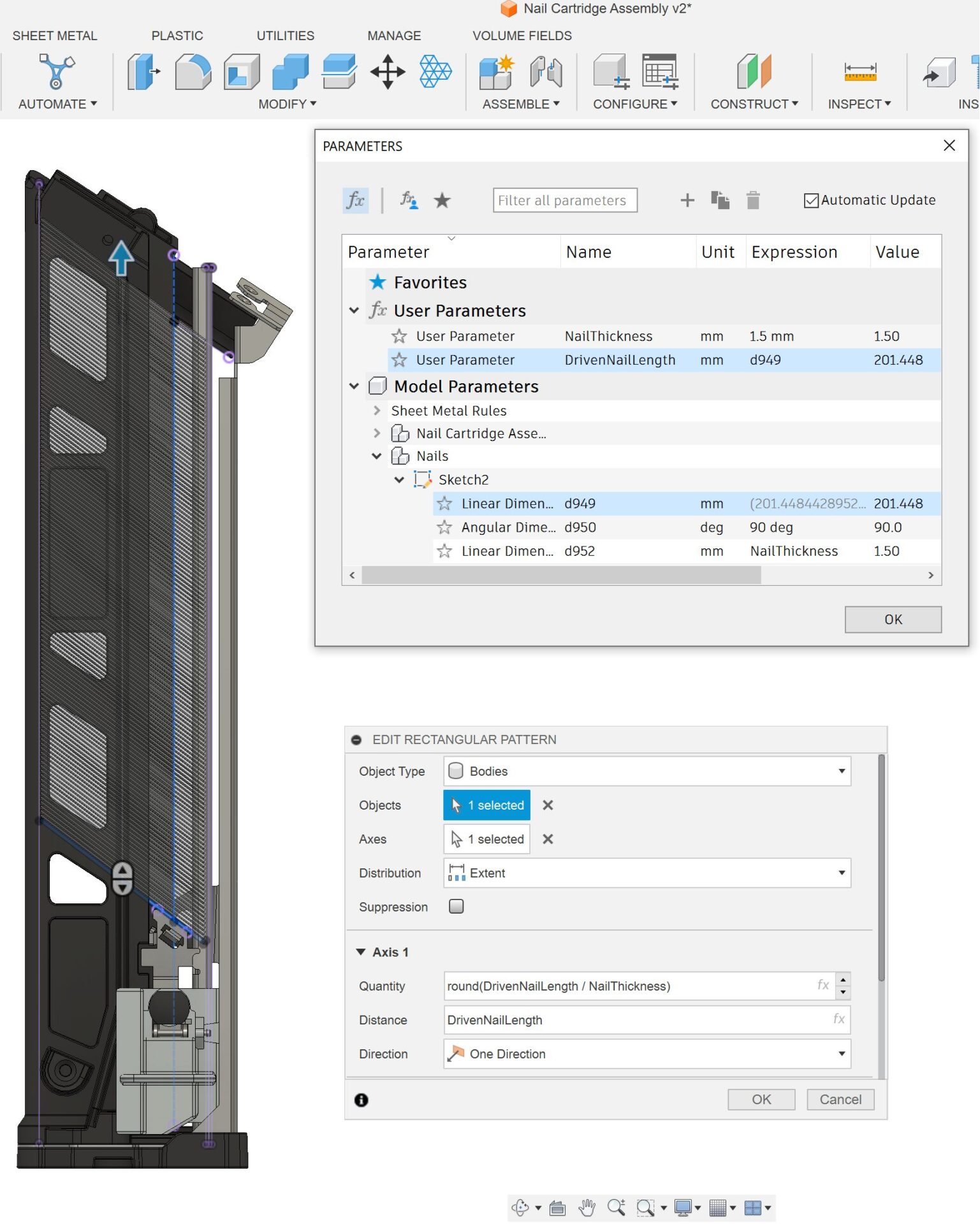
With this new enhancement to Refer Driven Dimension, you will be able to reference a driven dimension outside the Sketch in which it is defined. This means you will now be able use the value of a Driven Dimension to drive any equation or feature you like, replacing the need for complicated equations. Additionally, Driven Dimensions can be referred to anywhere in Fusion just like normal parameters.
New Internal Components Properties Configuration
As many of you know, in September we released Configurations. Configurations are a game changing feature that allows you to reuse parametric logic to create variations of a design in Fusion 360. With this release, Configurations just got better. As of the October release you can now add and configure properties for internal components within your configured designs.
To add an internal component’s properties to the Configuration Table, select a component in the browser:
- In Configuration Mode, click the component and check Properties.
- Outside Configuration Mode, right-click the component and select Configure. Then check Properties to add it to the table.
Configuring properties allows you to have greater control over your part data while improving your management of components in downstream workflows.
More Surface Options Available When Using Edit in Place
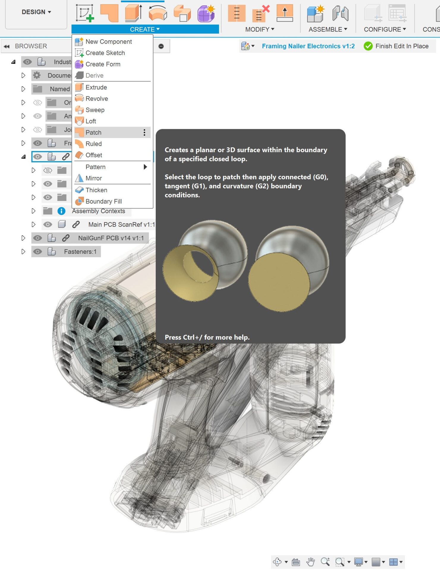
The surface offset and patch creation commands are now available when using the edit in place functionality, making it easier than ever to perfect your designs.
Improved Discoverability of Self-intersections During T-Spline-to-BRep Conversion
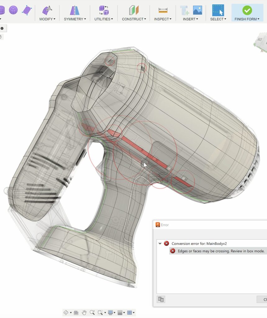
Previously, when a T-Spline-to-BRep conversion failed, it was hard to find self-intersection areas. Now, red circles will display around self-intersection areas making it easier than ever to identify problematic geometry.
Generative Design
Major Updates to Die Casting Manufacturing Constraint (Insider Preview + Generative Design Extension)

In this update, we updated our Die Casting manufacturing method to our commercial solver stack. This means the Die Casting manufacturing method will support all loads and constraints, symmetry, displacement limits and all the features in the Experimental Generative Solvers and Features Insider preview.
In addition to adding support for more functionality, we also made major changes to our algorithms to improve shape quality and manufacturability. You will now see better handling of undercuts and smoother geometry overall. Note, as this is still in preview, you may see some localized undercuts at the transition from generated geometry to preserve geometry. This is something we are actively working on and will be improving in future updates.
Be sure to join the Insider Program, give this update a spin and let us know what you think.
Drawings
New Surface Model Support
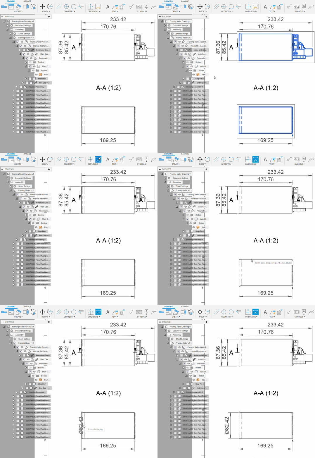
Seamlessly create drawings from surface models. If you have a surface model concept that you’d like to document, no problem. Been sent a 3rd party model, with surface bodies that are not quite water-tight? We got you. Drawings fully support dimensions, annotations and model updates to surface bodies, in fact, we treat them just like solids.
New Mesh Model Support
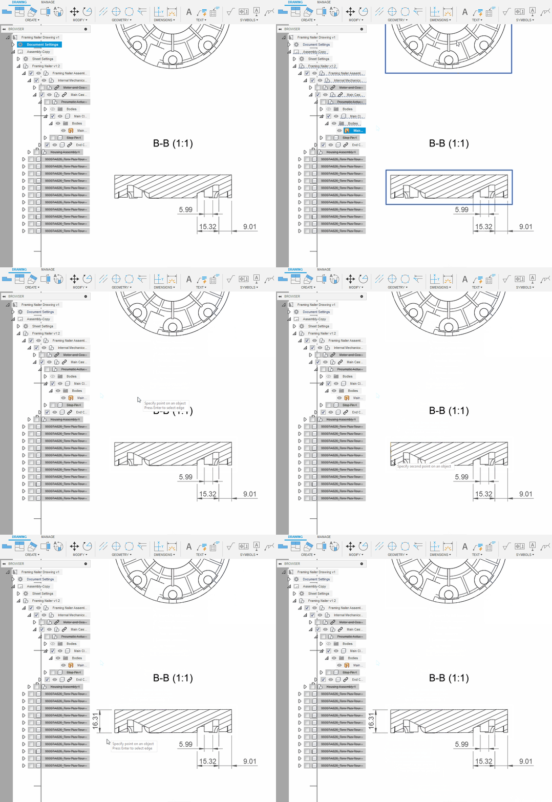
You can now create drawings of Mesh models. If you have an STL file (or similar) and are looking to document it, or have a mesh component in an assembly, we now have support for Mesh in drawings. Dimensions can be placed using linear point-to-point dimensions, we even support section views & annotations.
New Line Type Scale
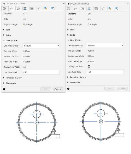
We’ve added a setting for line type scale to document settings. If you’ve ever had a small view, where the hidden or center lines seem a bit too big, or a large view where they seemed too small, this new setting will let you control the scale and appearance of dashed lines in your drawing. It is a global scale that applies to all views in a drawing.
Learn more about line type scales.
Custom Text Height Controls
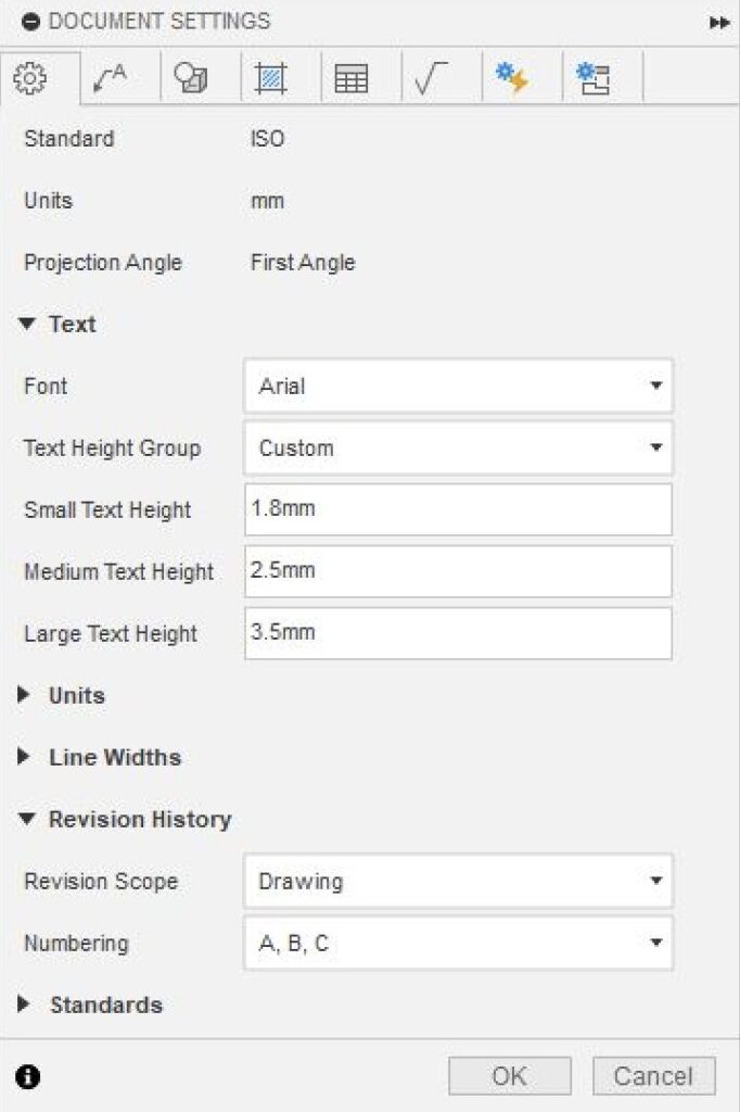
You’ve been asking for more flexibility when it comes to text heights. So, we’ve changed how custom text heights work in document settings. For custom text heights, you can now specify any text height (as long as it’s a positive value).
Learn more about custom text height controls.
Electronics
Utilize Mechanical Construction Geometry within 3D and 2D PCB
Considering your mechanical enclosure when designating the placement of your electronic components is an important part of the electromechanical workflow. Examples of this include connectors, switches or encoders aligned to a key mechanical element within the mechanical enclosure.
Previously in Fusion, as all PCB routing must be designed in 2D PCB (and therefore out of context to important 3D elements of the mechanical enclosure), it was difficult to keep track of optimal component locations. This guesswork led to frequent cumbersome iterations between 2D & 3D until your component placement is ‘just right’.
Today, we introduce the ability to create mechanical driven-construction geometry from 3D PCB (or a mechanical assembly context) into 2D PCB. Construction geometry does not affect any manufacturing data and is merely a visual geometry reference during layout design. It is now possible to define important areas of a mechanical enclosure within 3D PCB (or 3D PCB Edit in Place Assembly Context) and consider that geometry live alongside your layout design process.
Learn how to create a sketch on a 3D PCB.
Improved Layer Naming Alignment
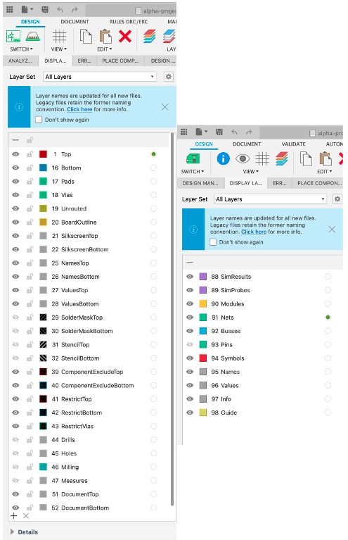
Previously, Layer names in Fusion 360 Electronics were confusing and not aligned with industry standards. E.g. ‘tCream/bCream’ has now been renamed to ‘StencilTop/StencilBottom’. In this update, we have revamped the names of all of our layers to help you better understand and navigate your design. For a full list of layer name changes and their legacy equivalent, please refer to Layers and their usage.
Important: Layer names have been updated to map more closely with industry terms. This change does not affect legacy files. You may see new names, legacy names, or a combination of the two as you work with the product. Additionally legacy layer names have been aliased meaning your existing ULPs / Scripts will not be affected.
Library Experience Improvements
Previously, you could open a library from a different Fusion team, even though you were unable save to it. With this update, only the current team library will be available. This will help prevent you from trying to add new parts into a different team’s design, which will result in missing data.
Also with this update, when a Fusion library is opened, it will check to ensure that the most recent version of each package is being used. If an update is available a prompt will be provided to you. This helps to prevent data issues where package versions exist across multiple libraries.
New Signal Integrity Access for EDU
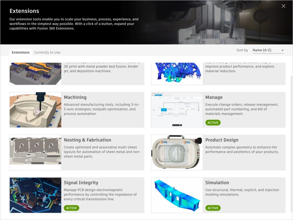
The Fusion 360 Signal Integrity Extension, powered by Ansys, is a cost option that unlocks additional PCB/electronics signal integrity tools and capabilities inside Fusion 360, allowing you to run electromagnetic analysis on critical signals within your PCB.
The Signal Integrity Extension enables product designers and engineers to inspect and resolve issues with PCB signals early in the design phase to improve product EMC and EMI (Electromagnetic Compatibility and Interference) testing compliance, reduce costly physical PCB testing and prototyping, and accelerate development.
As of this October educators and students alike now have free access to the Signal Integrity extension.
Electronics Performance Improvements
We recognize how important performance and productivity is to your Electronics design workflow. Thanks to rigorous internal testing & your feedback, we were able to identify and resolve multiple performance bottlenecks. In this update, you will notice performance improvements across Fusion Electronics including:
– Multi-window-multi-monitor
– Document Switching
– General user-interface interaction
This is an active investment from our teams, and we will continue to bring improvements to performance & productivity in future releases of Fusion 360. We really appreciate the time taken to give feedback – this helps us identify and prioritize bottlenecks like these.
Manufacturing
New Geodesic Toolpath Strategy
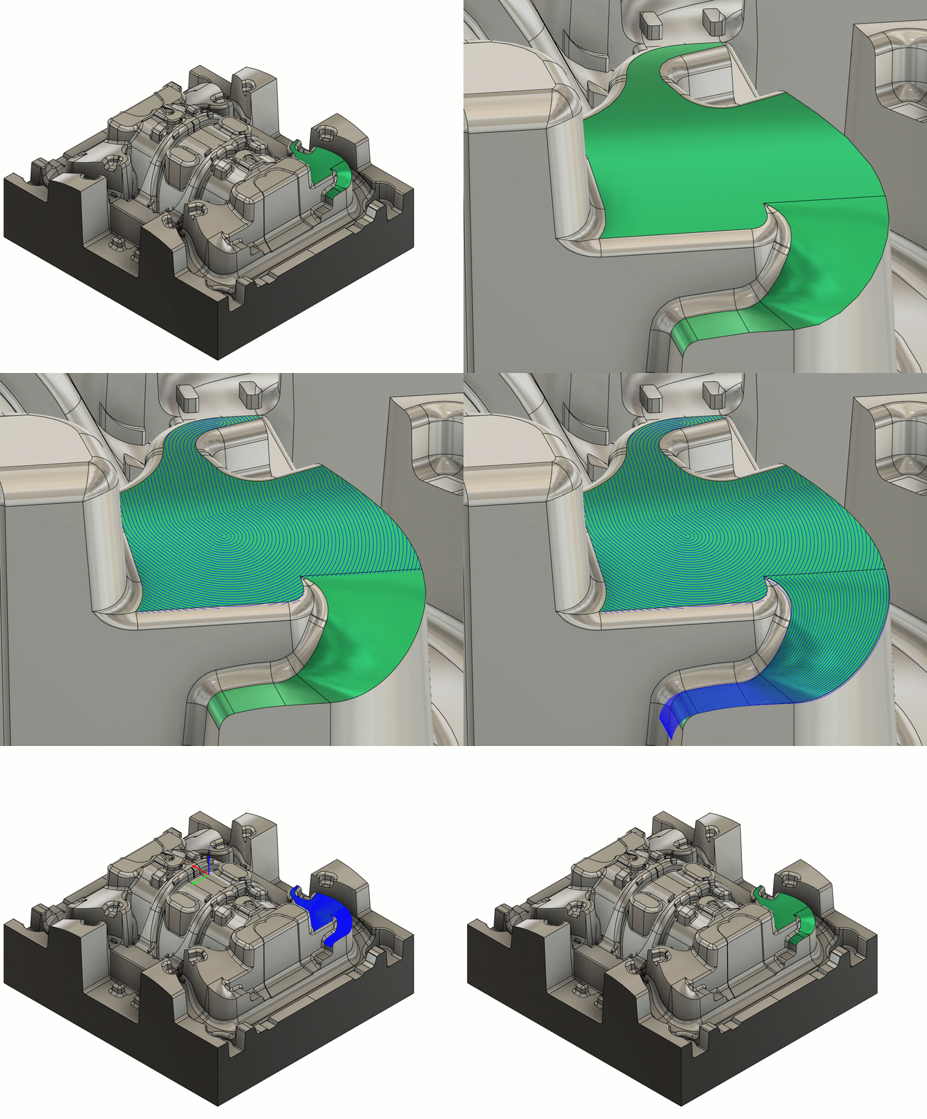
Geodesic toolpaths allow freeform surfaces to be machined using either a Blend or Scallop type. Blend is useful for machining between two similar curves and creates passes that smoothly vary between those curves. Scallop is useful for machining most freeform surfaces as it creates a constant offset from a machining boundary of specified guide curves.
Geodesic can create 3-, 4- and 5-axis toolpaths, will machine undercuts, and has the option for collision avoidance by automatically tilting the tool.
Note: The 3-axis version of Geodesic will remain as core functionality. The Machining Extension will not be required to access the 3-axis technology. The 4-axis and 5-axis technology will require the user to have access to the Machining Extension in order to consume the multi-axis technology.
Learn more about the Geodesic strategy.
Information about Fusion Design “threads” passed into manufacturing
Now when you create a tapped hole or thread feature in Design space, the information about that thread (e.g., M10x1, 60 degree, right-handed, etc) will be available to be used in the Manufacture workspace. To access this ability, you can now simply use “parameters” within the toolpath that begin with auto_xxxxx. For instance, auto_threadPitch can be used as an expression when entering the “pitch” for a milling or turning thread operation. This is completely associative, so when you update the model in the Design space, the changes will flow through into your toolpaths!
Fusion will ship with an additional template with all the Auto_expressions all pre-specified so all that you will need to do is select the thread and it auto calculates all the correct thread parameters going forwards.
Learn more about expressions in the Manufacture workspace.
New Open pockets in Wrapped Toolpaths for 2D Adaptive
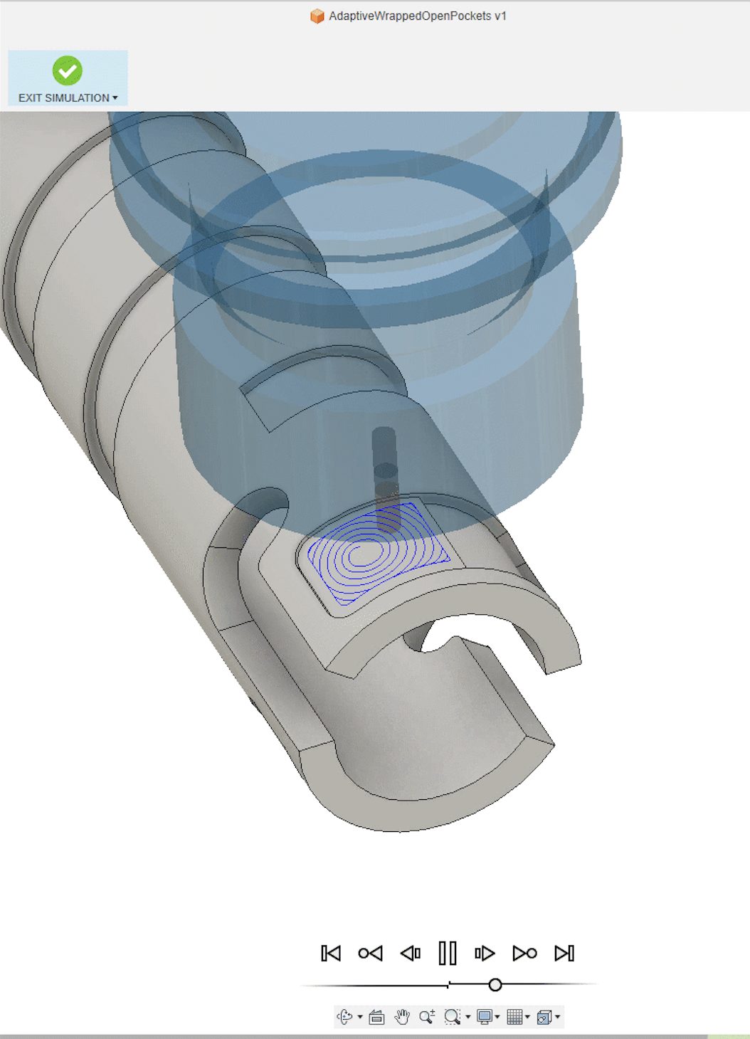
We now offer support for machining open pockets in wrapped adaptive and pocket toolpaths. This feature is well suited for 4-axis milling and is suitable for Turn/Mill machines without a Y-axis. Wrapped open pockets act as a great way to improve entry moves into stock.
Order optimization for 2D Pocket and 2D Adaptive contours
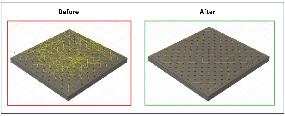
Previously, when you selected multiple contours at different heights, each contour was treated as a different operation, making it so the order appeared random and you could not optimize the order effectively.
We have made improvements to the ordering to handle contours at different heights. The order behaves predictable and you can now optimize the order as expected.
New Ability to Export Slices as TIFF files
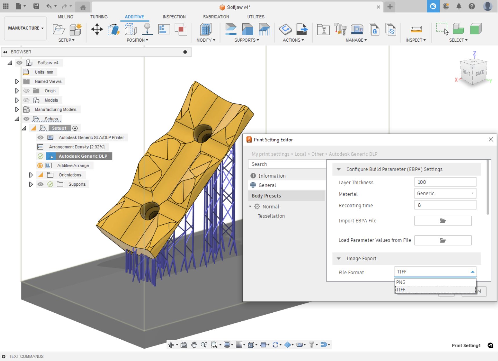
You can now choose whether to export your slices as PNG or TIFF files when selecting a DLP printer / print setting.
Learn how to edit print settings.
New Option to Recognize Partial Holes in Hole Recognition (Machining Extension)
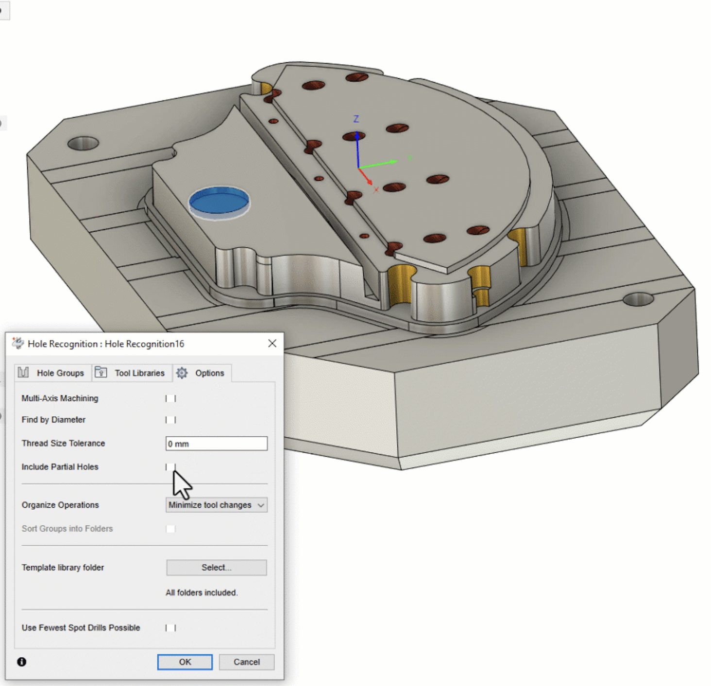
Previously, one of the limitations we had for what was considered a ‘hole’ was that it had to be a complete cylinder. This was done on purpose to eliminate finding things like corner radii of pockets and recognize them as a ‘hole’. As of this update you now have the ability to include partial holes or non-cylindrically complete shapes during automated hole recognition.
This feature is especially useful if your part has many holes that aren’t diametrically complete. To use partial hole recognition a yes/no option to include partial holes in hole recognition dialog will now be available in the options tab for you to check. You will still be able to use multi-axis capabilities to detect those partial holes on faces which require 3+2 tool orientations on holes which are not aligned to tool orientation or Setup Z to begin with.
Post Processor and Machine Simulation Update

Looking for the latest post processors and machines updates? This October we released a ton of new updates and improvements to many of the open-source Post Processors and Machines we offer for free. Within this release you will find the addition of milling post processors for Kern Micro, as well as improvements to many milling post processors, mill-turn post processors, and setup sheet post processors. Additionally, we added new machines to our Machine Library, updated and improved our Workholding library, and improved functionality around the Autodesk CAM Post Processor engine.
Learn what’s new for Post Processors and Machine Simulation this October.
Learn what’s new for Post Processors and Machine Simulation this November.
Additive Manufacturing
New Build Time Calculation for an Additive Setup with a Metal Powder Bed Fusion Printer (Additive Extension)
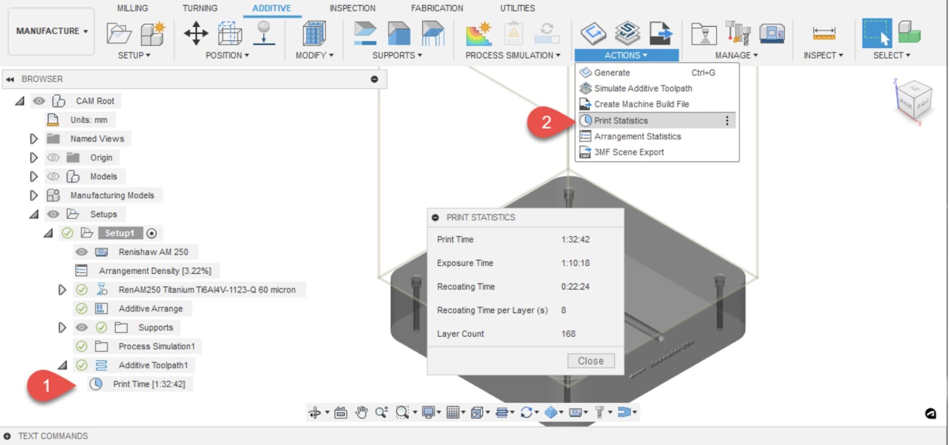
We now show the build time calculation for an additive setup with a Metal powder bed fusion printer.
Learn more about how to display print statistics.
Automatic Orientation Performance Improvements
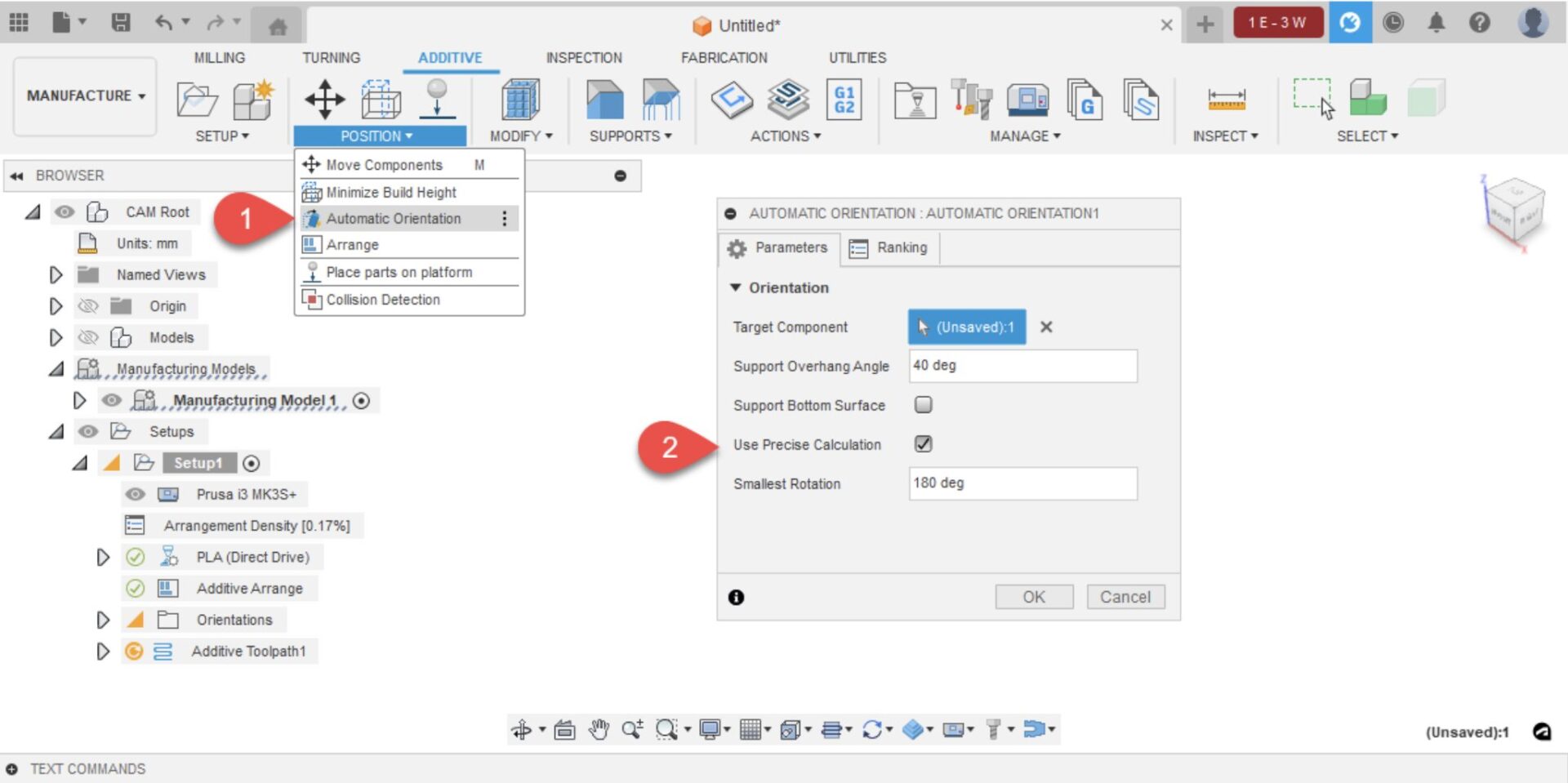
The automatic orientation dialog now has a checkbox to enable/disable the use of a more precise calculation method when calculating the necessary support structures. Using the precise method accounts for supports terminating at an up-skin region of the selected part, and results in a more accurate calculation of potential support volume for each orientation when ranking outcomes. Disabling the precise method ignores the up-skin regions and calculates support volumes purely based on the down-skin regions of the selected component. This results in a less accurate support volume calculation, but users can achieve automatic orientation results much faster.
Disabling the precise method is useful when we are searching for orientations for Additive MFG technologies that can print without the need for support (example: SLS, Binder jetting etc). In such cases uses don’t need accurate support volume calculation while searching for an orientation.
Learn how to create an Automatic Orientation study.
Simulation
Synchronize Legends now available in Compare for Injection Molding Simulation (Simulation Extension)
Injection Molding Simulation > Results > Compare > Sync Legends
When comparing results for Injection Molding Simulation studies, you can now synchronize result legends where the legend values (Min and Max) displayed in the compare windows will be synchronized with the Minimum and Maximum legend values for that result. Note that in order to sync legends the same result should be active on all of the Compare windows. Along with synchronizing the legend Min and Max, we also synchronize the Range of interest where the range for all windows will be modified in synchronization when the user modifies the range for the result in the active window.
Synchronize Results now available in Compare for Injection Molding Simulation
Injection Molding Simulation > Results > Compare > Sync Results
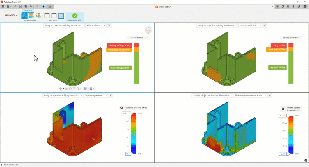
When comparing results for Injection Molding Simulation studies, you can synchronize results where the results displayed in all of the compare windows will be synchronized with the result displayed in the active window. Switching results from the active window will switch the results in all compare windows. If a particular study does not have that result available, then an icon indicating the same will be displayed in the window for that study.
Injection Molding Simulation Material Database Updated
The Injection Molding Simulation material database has been updated to give a more comprehensive database of both materials and manufacturers:
- Total number of New Materials added: 1304
- Total number of Materials updated: 632
- Total number of Materials deleted: 87
- Manufacturers deleted: 4
- New Manufacturers added 36
- New Total number of Materials: 12848
- New Total number of Manufacturers: 595
Performance Improvements in Simulation
We have made improvements in various parts of Simulation:
- Manage contacts dialog display speed has been improved by 20x to 30x.
- Closing a document would take too long when lots of result blobs were present. This has now been improved by 18-20%.
- Suppressing large quantities of bolt connectors would take a long time (~40 minutes) in a large dataset. This has been improved where suppression would now take only a few seconds.
Data Management
Improved Manage Extension Experience (Manage Extension)
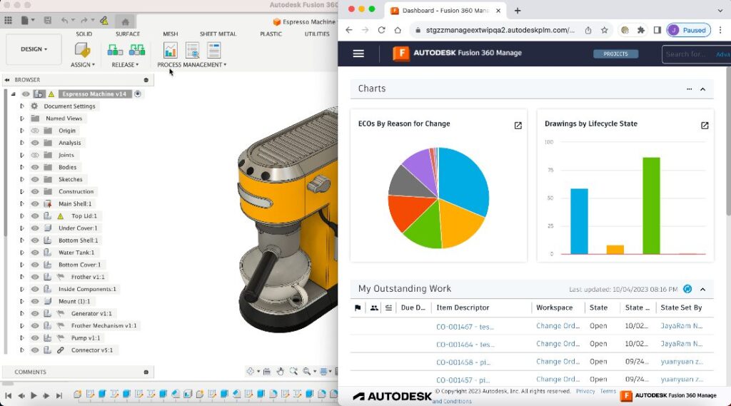
We’ve streamlined the experience with the Manage Extension. To start, we’ve improved the navigation experience to recents and project data with the updated Home Tab. We’ve also moved the access to the Manage Extension dashboard, item details, and change orders from the Home Tab directly to the Manage toolbar. Selecting these new commands will open the corresponding data within the web experience, providing better performance.
API and Add-Ins
Sample Add-Ins can Now Load on Startup
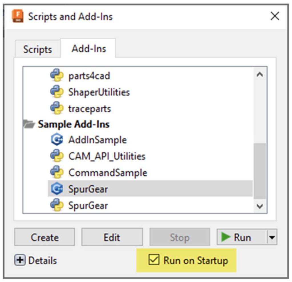
It’s now possible to change the “Load on Startup” setting for the sample add-ins that are delivered with Fusion. Previously, this option was disabled for the sample add-ins. This is especially useful for those of you who frequently use the SpurGear or CAM_API_Utilities samples. By setting the add-in to run on startup, the Spur Gear command will always be available in the “CREATE” panel without using the “Scripts and Add-Ins” command to load it in each session.
API Access to Scripts and Add-Ins
There is now API support for the equivalent capabilities of the “Scripts and Add-Ins” command. Here are some things you can do:
- Create a new script or add-in.
- Iterate through all of the known scripts and add-ins.
- Determine if an add-in is currently running.
- Start and stop add-ins.
- Run scripts.
- Set or unset add-ins from running on startup.
- Get the path where the script or add-in exists.
This will allow some additional utilities to be written to allow better use and management of scripts and add-ins.
Full API Support for the Pipe Feature
The API now has full support for the Pipe feature. You can now create and edit pipe features in your scripts and add-ins.
Customer Reported Fixes
What’s Coming Next
Get a sneak peek at what’s to come in the 2023 Fusion 360 Roadmap and an understanding of the “why” behind the features we’re investing in.
DISCLAIMER: Roadmaps are plans, not promises. We’re as excited as you to see new functionality make it into the products, but the development, releases, and timing of any features or functionality remain at our sole discretion. The projects mentioned in this roadmap are highlights and do not account for ongoing efforts like bug fixes, platform, and service maintenance. These roadmap updates should not be used to make purchasing decisions.
Join the Insider Program

Want to engage more with the Autodesk community, use previews, and test out the latest build one month before it’s released to the general public? Check out the Fusion Insider program! The Autodesk Fusion Insider Program enables you to access the next version of Fusion and all the new features, improvements, and fixes, 3-4 weeks before the general public. As a member, you’ll gain inside knowledge of when we are deploying an update, what’s new, and what’s coming next . You will also have the opportunity to join exclusive events, try pre-release functionality, and give feedback straight to the product teams.