See how this F1-inspired steering wheel designed and manufactured using Autodesk Fusion showcases the software’s breadth of capabilities.
The secret to successfully developing world-class consumer products lies, in part, in having access to professional-grade design & manufacturing software that supports the entire product development lifecycle. From initial concept design to mechanical and electrical engineering, to product simulation and validation, all the way through to production and beyond; it is essential that modern software provides the collaborative tools needed to bring those products to market. In this article, we chart the story of a team of passionate designers and engineers who decided to put Autodesk Fusion through its paces.
It started with a conversation between two friends one evening over a cold beer. “How cool would it be to test Fusion out by designing and making our very own steering wheel?”. This innocent question, from Autodesk technical sales specialist – and project lead – Christopher Derdak, started a project that would see an international team of specialist designers and engineers work with a global network of OEMs to design and make a complete F1-inspired SIM racing steering wheel.
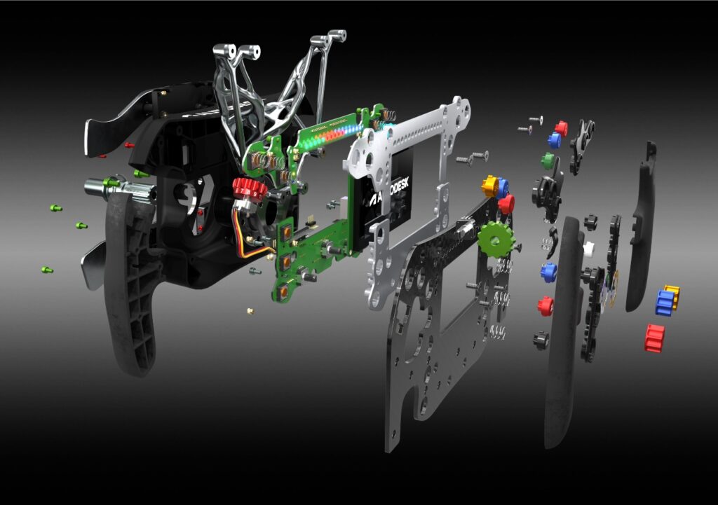
Every race begins with the first step
The project began with a simple concept sketch of the shape of the product. Derdak took inspiration from his own experiences in the SIM driving community and was inspired by many of the modern F1 steering wheels. Using Fusion’s intuitive interface, Derdak quickly converted the concept into 2D wireframe profiles to represent the size and shape he had in mind.
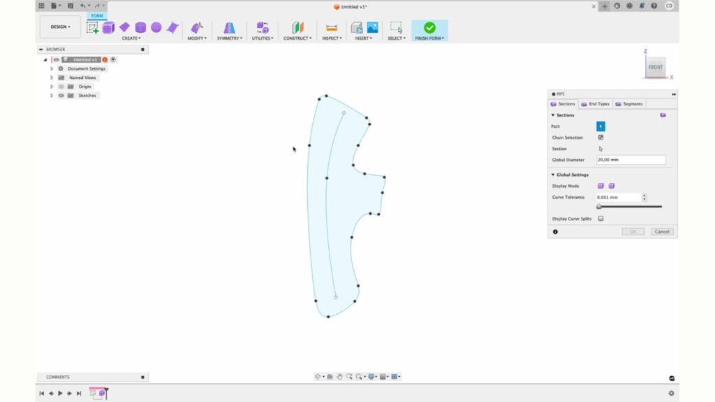
Having created the initial 2D sketches, Derdak focused on producing the main component parts using the full suite of solid and surface modeling tools contained within Fusion’s Design workspace. Using intuitive free-form modeling, Derdak was able to combine prismatic shapes with organic forms, until the desired 3D aesthetic had been achieved.
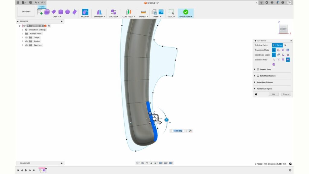
Once the outer aesthetic components were complete, Derdak focused on the inner mechanical parts, including switch gear, shifter paddles, quick release mechanism, as well as all of the fixings that would be required to assemble the finished wheel.
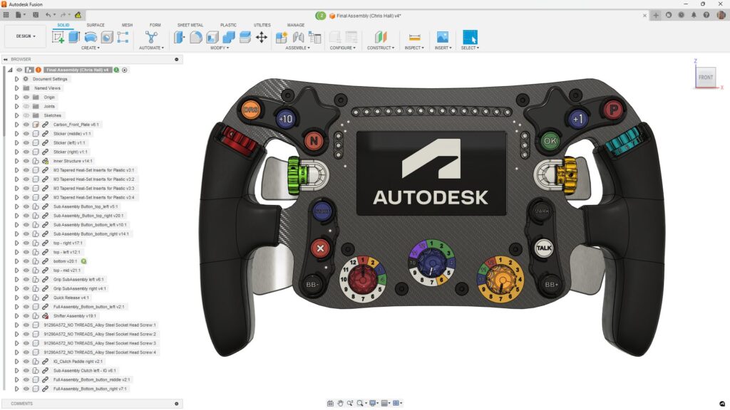
As you might expect, these individual component parts weren’t designed in isolation. Instead, Derdak used Fusion’s cloud-based data model to securely share his project with his extended team of designers and engineers.
This collaborative approach was maintained throughout the life of the project and ensured the team was always working on a single, unified design – not separate, disconnected models stored in individual folders on local computers. From the very beginning, the team knew that, if the industrial designer made a change – which happened quite often in the early development stages – the changes would be instantly available for everyone else to review and consume. This allowed the team to adapt and pivot quickly and easily.
“During the final design stages, we had to do a lot of fine tuning and change positions of internal parts to make sure they fit. With Fusion we could easily share these updates within our cloud shared project with the rest of the team.”
—Christopher Derdak, Technical Specialist, Autodesk
Mechanical meets electrical engineering
Having designed the main component parts, Derdak engaged the services of Autodesk electronics expert, Richard Hammerl to begin the process of designing the printed circuit boards (PCB), switches, and other components that would allow the steering wheel to function.
Unlike legacy software solutions, where data is often exported from one CAD design software tool to another, Derdak simply invited Hammerl to participate in his Fusion project. This removed the need to export files and meant no loss of data due to translation issues. Instead, Hammerl simply used his unique invitation to securely access Derdak’s project; at which point the PCB design could begin.
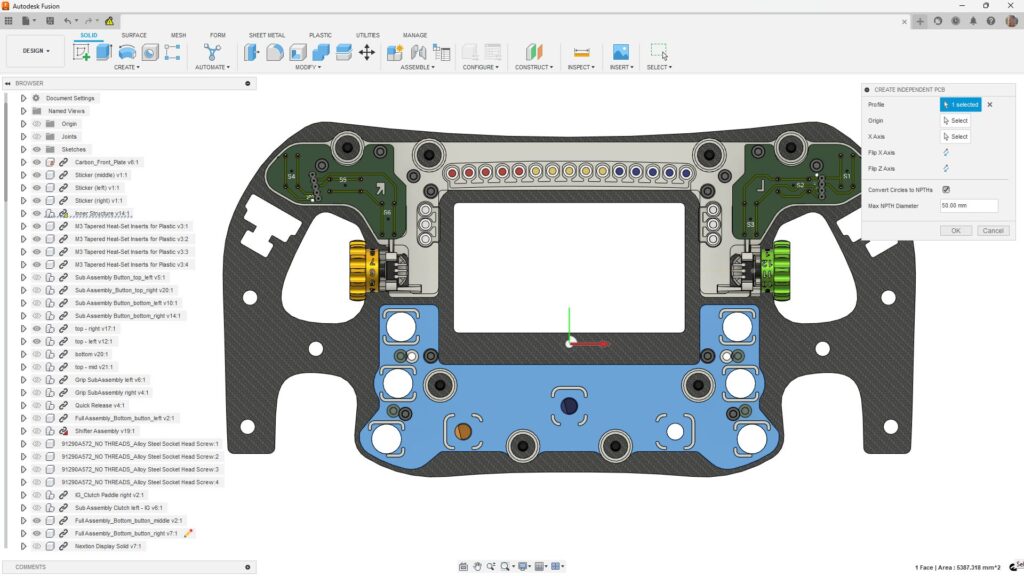
Due to the limited space in the steering wheel, Hammerl opted to design four individual circuit boards. Each of the PCBs has an individual, unusual contour. The PCB design process really begins with the selection of a 3D component from the main steering wheel assembly. In just 3 mouse clicks, Fusion derives a blank PCB board from the selected component, updates the profile to include any drill holes or cut-outs, and then transfers the shape to the 2D workspace. This task was completed in just a few minutes, something that would have taken at least two days in other, less capable systems. At this point, Hammerl turned his attention to building the circuit. This was achieved using Fusion’s cloud-based library of standard electrical parts to select and position key components on the board to form the desired circuit.
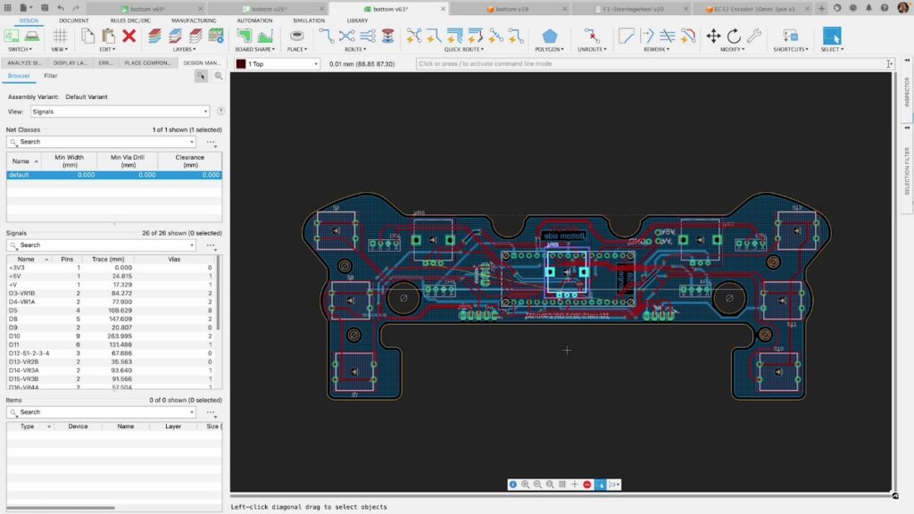
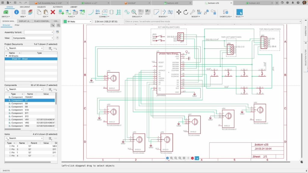
In addition to creating a 2D view of the PCB – useful for showing the actual size, shape, and position of the individual element on the PCB – Fusion also provides a 2D schematic layout of the circuit. This is especially useful as it allows the engineer to focus on the connections with a circuit without being distracted by the shape of the individual parts.
As well as creating simple 2D views, Fusion can also create a 3D model of the PCB with a single mouse click. Crucially, as the library of component parts is both 2D and 3D, each time an encoder, switch, or LED was assembled into the schematic – or moved to a different position – all views, whether 2D or 3D PCB, will automatically update. Making a change in one view will be reflected in the others. This speeds up the development process and allows the designer to check for potential collisions or interference with other mechanical components; something that can be potentially disastrous (and expensive) if left until final part assembly.
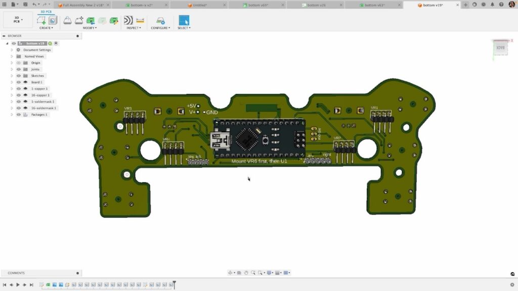
The associativity within Fusion isn’t limited to the connection between 2D and 3D views of the PCB. In fact, the associativity stretches across the entire design of the full product. This proved especially useful in the early stages of the design where Derdak was experimenting with the position of fixing holes to accommodate a larger grab handle – and Hammerl had to ensure the PCB design kept in sync.
As both industrial and electronics designers are working on the same dataset, the modified grab handle design was instantly made available for the electronics engineer to carry out additional checks with the PCB board. If interference occurs, individual components (or indeed the entire PCB profile) can be updated with minimum effort – with all 2D and 3D views being updated in minutes.
“Due to the limited space in the steering wheel, we opted for four individual circuit boards. Each of the PCBs has an individual, unusual contour. Thanks to the option of creating a PCB in 3D from a mechanical sketch or a housing, including the drill holes and cut-outs, with three mouse clicks and then transferring it to my 2D workspace, this task was completed in just a few minutes. If I think back to my old layout tool, this would have taken at least two days.”
—Richard Hammerl, Technical Specialist, Autodesk
Once the design of the PCBs was finalized, the datasets and associated 2D drawings were shared with German-based electronics manufacturer, Eurocircuits, who were responsible for a small production run.
Generative design assists chassis design
To reduce the overall product development time, it is commonplace for multiple designers and engineers to work concurrently; this was certainly the case on this project. As Hammerl was busy working on the PCB designs, another team worked on other mechanical elements.
Rene Schricker, Autodesk Technical Solutions Engineer, was tasked with creating the main structural chassis of the wheel. This critical component forms the backbone of the steering wheel and must resist the forces applied to it during use. It also needs to be designed such that it fits around the other internal component parts.
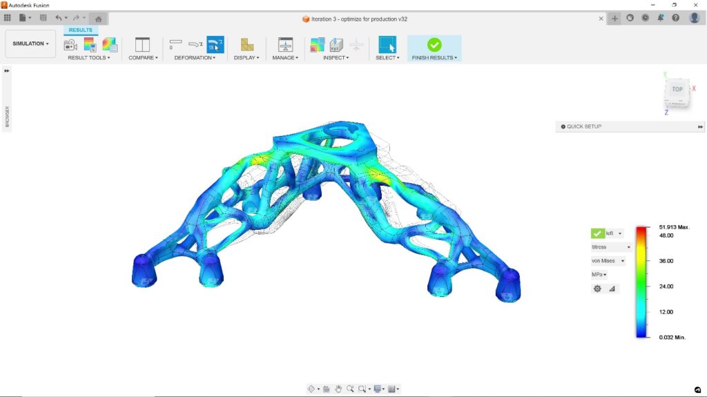
Here, Schricker decided to employ generative design inside the Autodesk Fusion Simulation Extension to explore different design solutions. He started by defining geometry that must be preserved; fixing points where the chassis needs to attach to other components. In addition, geometry was selected that should be avoided, such as the overall 3D volume of the inside of the wheel and other internal parts. The avoidance geometry consisted of static components like the PCB and moving parts such as the internal switchgear.
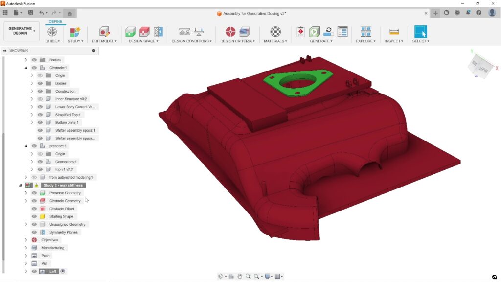
Next, Schricker defined the expected loads that would be experienced in service and focused on different manufacturing processes that could be employed. From the growing list of supported methods (3D printing, plus 3- and 5-axis CNC machining, and casting), Schricker chose additive manufacturing combined with stainless steel AISI 304. Once all variables were defined, Schricker used Fusion’s cloud-based computing to create multiple different designs while he continued working on other tasks.
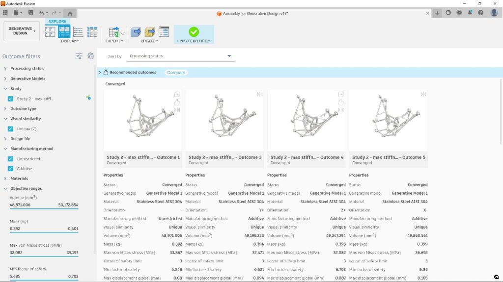
In less than an hour, Fusion had produced more than a dozen viable designs. Fusion can display the designs in different ways, including views that rank the different designs in terms of weight, volume, strength, and other criteria.
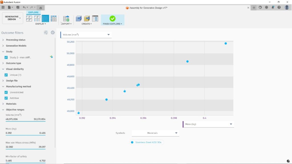
On this occasion, the initial list of designs was quickly reduced to a small number of preferred designs. At this point, Schricker simply chose the model that had the nicest aesthetic appearance; a few seconds later a complete 3D model was available inside Fusion. It’s worth noting that the 3D model is fully editable B-rep solid – not a triangle mesh – meaning further edits can be made (if needed) prior to assembling with the rest of the steering wheel.
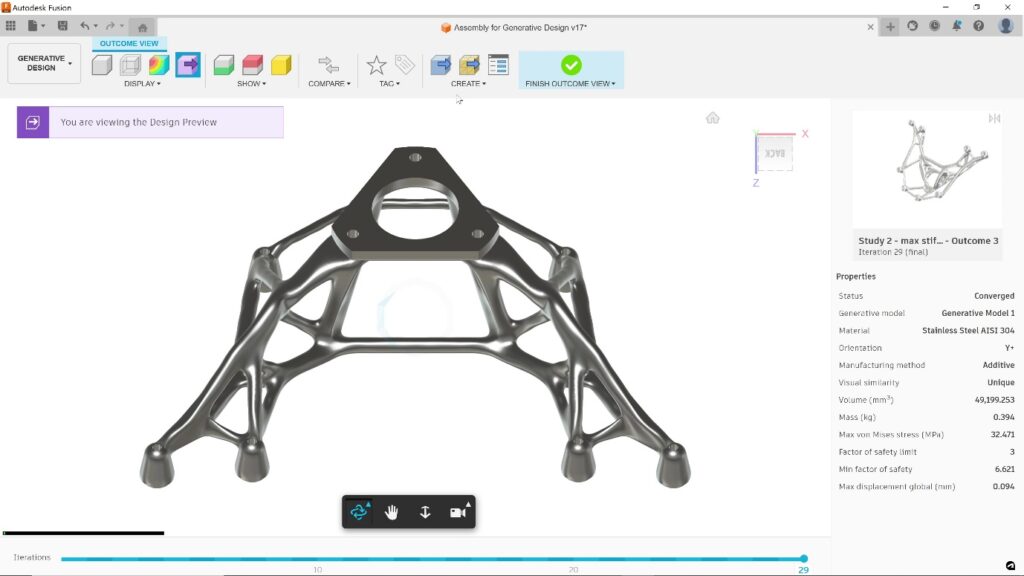
Before manufacturing could commence, Schricker was keen to check the performance of the part. He did this using the range of finite element analysis (FEA) tools contained in the Autodesk Fusion Simulation Extension. As before, these checks could be carried out inside Fusion, avoiding the need to export any data to third-party software tools. Reassuringly, the finished design passed every structural test – meaning it was approved and ready for production.
“Generative Design has proven to be the perfect tool for the Additive Manufacturing aspects of this project. With very little effort it created geometries that are perfectly optimized for 3D printing.”
—Rene Schricker, Technical Solutions Engineer, Autodesk
Wrapping up the design
As the team continued to work on the internal mechanisms, Autodesk Technical Specialist, Ignacio Madina, was given the task of completing the design of the outer molding that would encase the rear of the steering wheel. Madina activated the Autodesk Fusion Design Extension to unlock some of the more advanced modeling tools in Fusion. He began by taking the initial 3D design from Derdak – which was missing this critical back molding. He then created a 3D form using a mix of prismatic and organic surfaces. Once done, various ribs, bosses, and fixings were added to enable the assembly of the molding to the rest of the wheel.
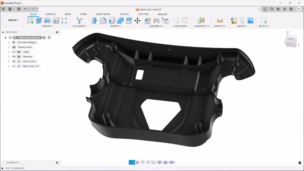
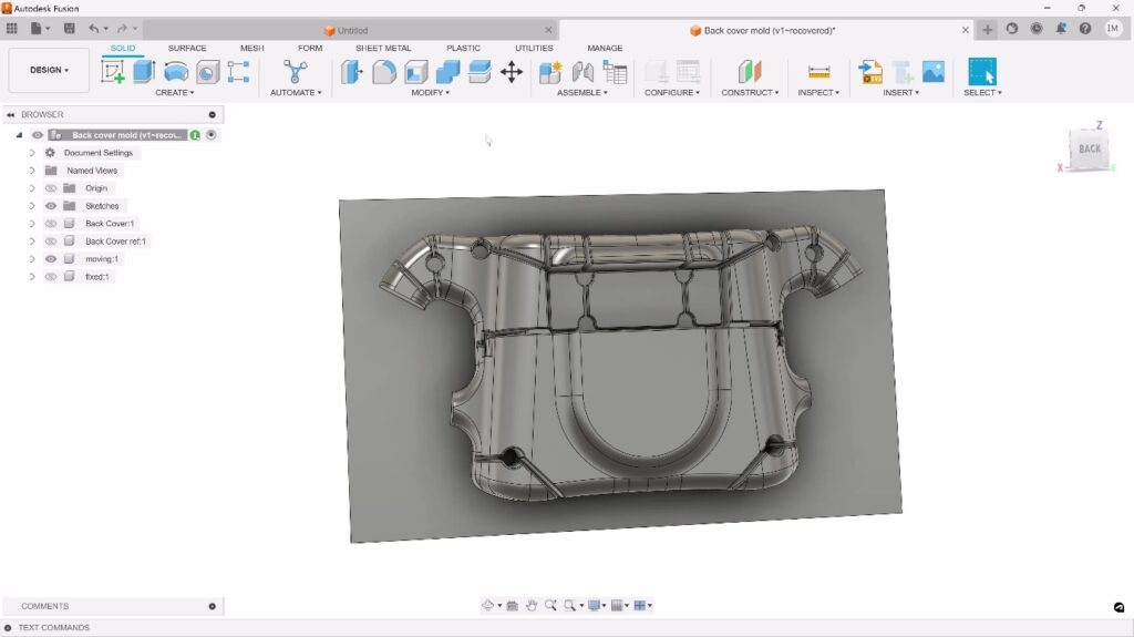
Having finished the design of the molding, Madina’s attention turned to converting it into the core and cavity blocks that would be used for a low-production run via injection molding.
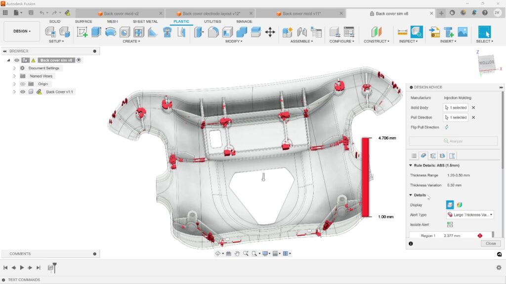
As before, the Autodesk Fusion Simulation Extension was used to check the plastic part to identify issues that can complicate the molding process, such as:
- Areas where wall thickness is thicker/thinner than optimum values. Why? This can cause parts to distort during molding which may compromise subsequent assembly or performance.
- Small, internal corners with radii smaller than a pre-defined value. Why? These can cause stress raisers in local regions of the part which, in time, can cause parts to fail while in service.
- The likely size and position of sink marks and weld lines. Why? These can result in visual imperfections appearing in the plastic molding which compromise the look, feel, and value of the molded part
- Near vertical faces with insufficient draft angle. Why? This can result in moldings failing to release during the ejection phase of the molding process.
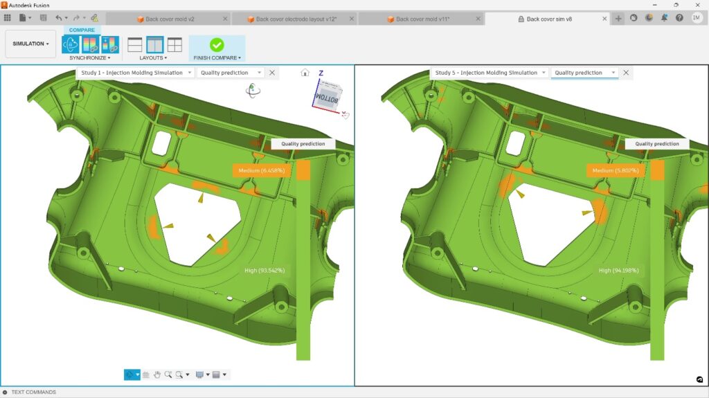
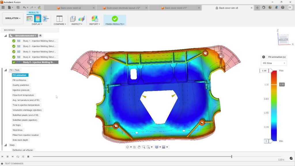
In addition to these static checks, Madina carried out dynamic simulations to visualize and validate the mold-filling process. A study was carried out to determine the potential impact on mold fill-time and molding success rate and compare the results if using a 2-point or 3-point injection solution.
Within seconds, Fusion provided the visual and numerical information needed to decide which solution to use. In this case, it was determined that the 2-point and 3-point solutions were similar in terms of fill time, but the 2-point option produced more desirable weld-line predictions.
“The simulation tools inside Fusion have been a life saver on this project. The manufacturing team had a single time slot when they could machine the molds and I needed to be able to check the moldability of the part and design the core and cavity blocks in just a few days. Thankfully, the simulation proved the design was good and the molds were finished in time for production to begin.”
—Ignacio Madina, Technical Specialist, Autodesk
Shifting gears into manufacturing
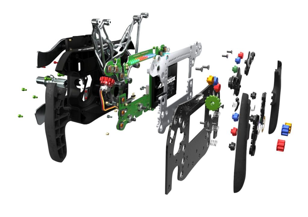
The remaining component parts were designed using a combination of approaches. In some cases, standard libraries of parts were imported from cloud-based libraries (for example screws, fixings, etc). Whilst other, non-standard parts were modeled inside Fusion. In total, the finished design consisted of 66 individual component parts (the PCBs were considered as single pieces). It was now time for production to begin.
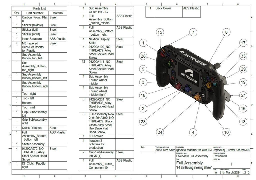
For production to happen, the team used Fusion to generate the usual collection of 2D drawings, renderings, and animations and used them to support internal and external communications. This included general assembly drawings, annotated sub-assemblies, detailed component drawings, and bills of materials. These were all stored centrally in Fusion and securely shared with colleagues, partners, and suppliers using Fusion’s “share link” option. The recipients of these links could instantly access the data they needed to begin planning production.
Additive manufacturing makes the impossible possible
Remember that crazy generative designed chassis that we covered earlier? Let’s talk about how it was made using additive manufacturing. This task was given to Thomas Stock, a Manufacturing Research Engineer based in the Autodesk Technology Center in Birmingham, UK.
Stock decided to use an MPRINT+ SLM machine as supplied by One Click Metal, but this presented an immediate challenge. The component itself was so large that it was unclear if it would fit inside the build volume of the machine. To find out, Stock activated the Autodesk Fusion Manufacturing Extension and used the specialist tools that it contains to orient and prepare the model for production before exporting manufacturing data to allow production to start.
Stock started by using the automatic part orientation capabilities in Fusion to calculate how to best fit the 3D part into the machine. Once the orientation was calculated, Stock noticed that there was less than 1mm of clearance around the 3D part – that is one tight fit!
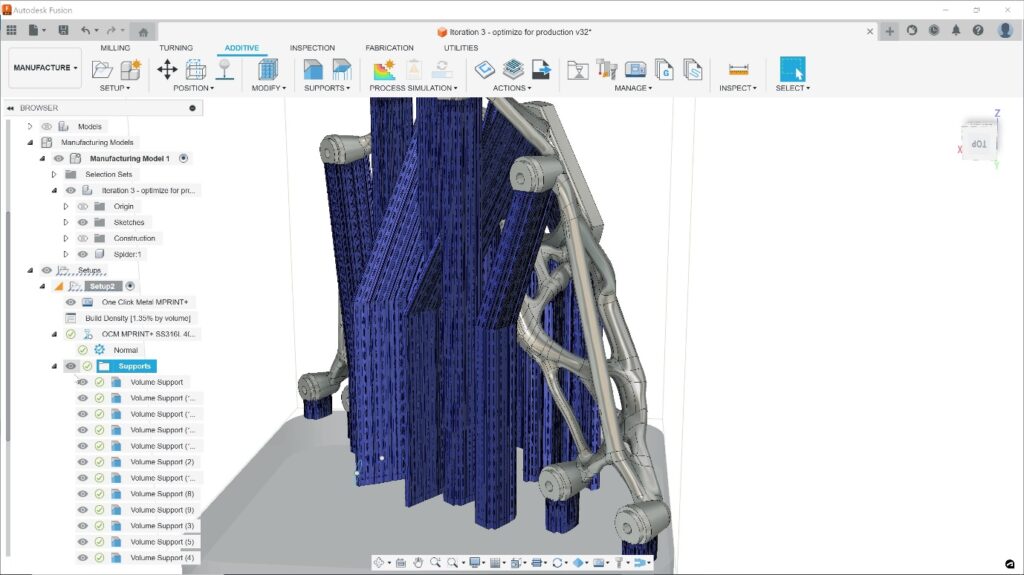
Stock then used Fusion to add associative support structures to the part to ensure it maintained its shape during the printing process (this is essential when printing parts with overhanging geometry). In minutes, Stock finished preparing the part for 3D printing and exported the necessary slicing data to the One Click Metal machine. The print itself was left to run over the next couple of days – completing 20 hours later.
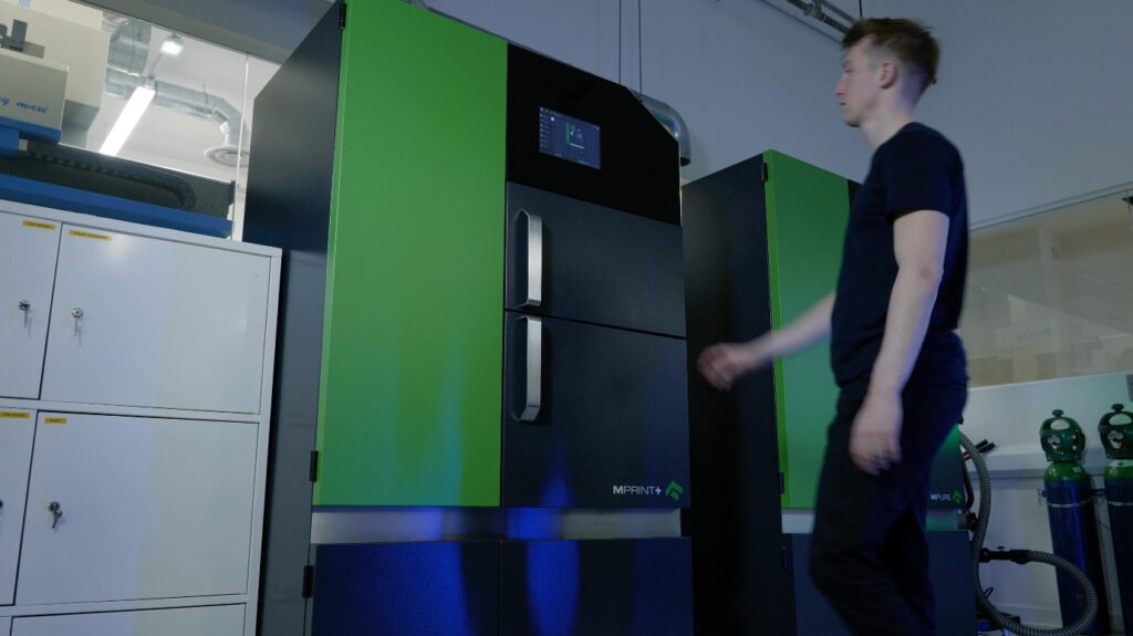
Once finished, Stock used One Click Metal’s MPUREpro unpacking station to sieve and recycle the surplus powder before removing the finished part from the machine. To complete the process, the part was cut from the build plate, support structures removed, and the part’s surface bead blasted.
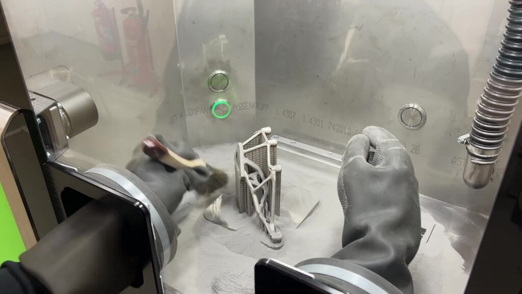
“This is definitely the most challenging part I have ever printed, and I was certain that it wouldn’t fit inside our machine. However, the orientation tools in Fusion did a fantastic job in fitting the part into the build volume – just. I am really happy with the end result.”
—Thomas Stock, Manufacturing Research Engineer, Autodesk

Subtractive machining brings precision where it’s needed
Most of the other component parts were manufactured either at Autodesk’s Technology Center in the UK or outsourced to a small network of suppliers. Let’s consider some of the parts made “in-house,” starting with the quick-release mechanism seen on the back of the wheel.

The production of this part was assigned to Manufacturing Engineer, and Turn-Mill expert, Christopher Cooper. Starting with the 3D dataset produced by Derdak, Cooper spent time considering the best way to manufacture the individual components that make up the quick-release mechanism. He knew that CAM programming would be challenging, so he activated the Autodesk Fusion Manufacturing Extension to unlock advanced CAM tools inside Fusion.
As with most CAM programming projects, Cooper had a good idea of how we wanted to machine the parts. Having picked the first component, he defined the machining setup inside Fusion and selected the appropriate tools from his cloud-based tooling library. Cutting speeds and feeds were automatically loaded from the library based on the stock material being machined.
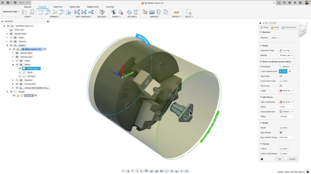
Over half a day, Cooper then created a suite of high-quality toolpaths that would be used to produce multiple, identical components from a cylindrical bar of stock. These included:
- Adaptive clearing toolpaths for initial part roughing
- Milling of non-turned forms with live tooling
- Hole drilling (aligned axially and radially with the part)
- Deburring (both 3- and 4-axis machine motion)
- Groove machining
Before actual machining took place, Cooper decided to use the simulation capabilities in Fusion to validate his toolpaths using a virtual representation of the stock material. This allowed him to check the quality of the toolpaths and identify any problems or mistakes in a virtual world, long before any actual cutting takes place – helping to avoid costly mistakes or machine collisions happening in the real world.
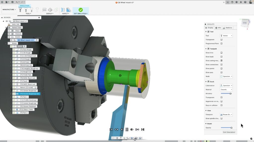
Once the toolpaths were checked, Cooper exported NC machining code to run on a DN Solutions (formerly Doosan), Lynx 2100LSY turning center, fitted with twin spindles, a single turret, and a Fanuc NC controller.

“The quick release mechanism contains some simple parts in terms of geometry, but there’s still a lot of CAM programming needed to get the desired accuracy and surface finish. Strategies like the automatic deburr mean the parts come off the machine looking great and not needing any extra hand finishing which saves me a lot of time and effort.”
—Christopher Cooper, Manufacturing Engineer, Autodesk
Mold production with CNC machining
Turning our attention to the manufacturing of the plastic molding discussed previously. Once the core and cavity blocks had been designed, the job of producing them was passed to Josh Reader, a Manufacturing Engineer who, like Christopher Cooper, is based in the Autodesk Technology Center in Birmingham, UK.
Reader began by interrogating the core and cavity blocks to identify issues that could complicate manufacturing. Challenging features such as deep ribs or small internal fillet radii were identified as these could be difficult/impossible to produce with CNC milling. In addition, Reader also used undercut shading to identify features or surfaces that would need (or benefit) from using 5-axis machining.
Like Cooper before him, Reader recognized the need for more advanced CAM programming tools and so quickly activated the Autodesk Fusion Manufacturing Extension. Once done he defined his machine setup (including defining the stock material, selecting cutting tools, and defining the workpiece coordinate system). Reader also identified the suitable CNC machine to use, on this occasion a DMG-Mori DMU 60 Evo 5-axis milling center.
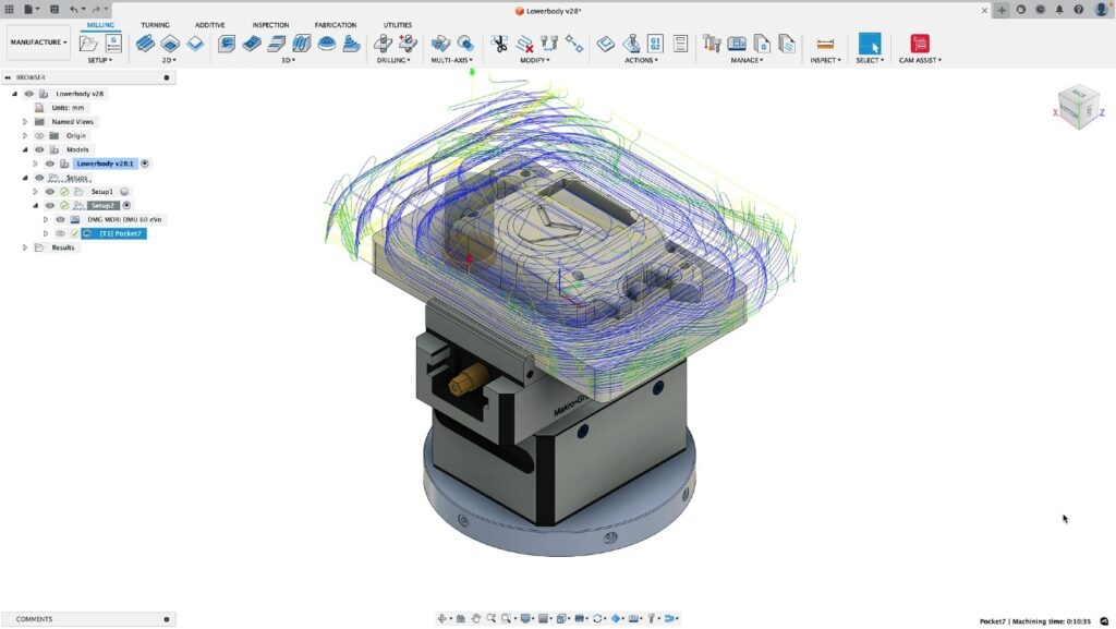
CAM programming the core block utilized many of the 3- and 5-axis toolpaths that Fusion offers, with roughing and finishing strategies being used, including:
- Adaptive clearing
- Pocket machining
- Steep & shallow finishing
- Geodesic machining
- Swarf finishing
- Flat finishing
- Hole drilling
- Deburring
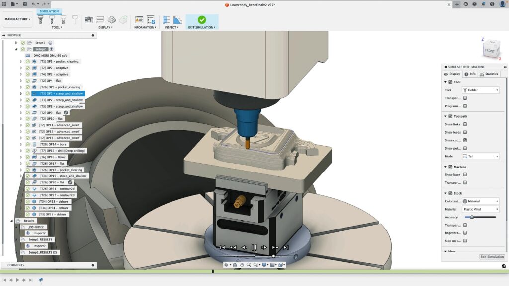
Once these toolpaths were created, Reader used Machine Simulation to check for problems such as collisions or near-misses involving the cutting tool, workpiece, stock, and machine. Fusion was also used to check the programs to ensure they remained within the axis stroke of the machine, avoiding the risk of axis over-travel. After all simulations and analysis were complete, Reader was confident all toolpaths were safe and ready for production.
Whereas Christopher Cooper did the CAM programming and machine operation, Reader worked in partnership with a dedicated machine operator; in this case Fernanda Medina Aguirre, a fellow Manufacturing Specialist at Autodesk. To help communicate exactly how the parts were to be machined, Reader produced detailed setup sheets containing information about the cutting tools that would be used, the exact position of machining datums, as well as the various strategies being used, and the feeds and speeds that were employed.
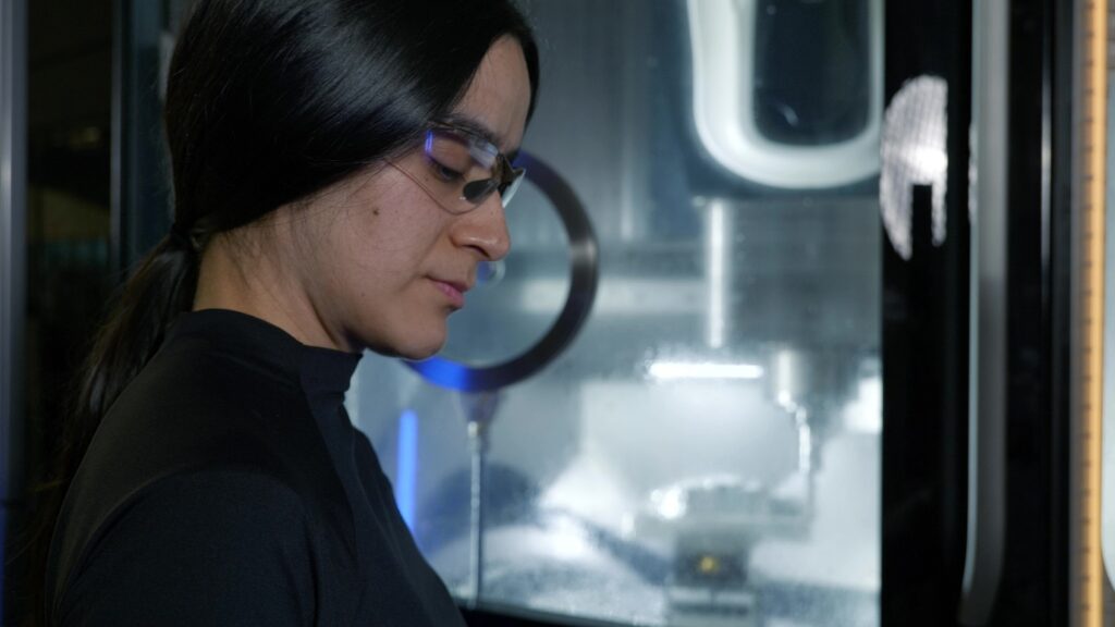
2D documents were combined with “shared views” that showed images and details about the 3D models and toolpaths; these were shared securely with Aguirre who worked with Reader to set up fixtures on the machine, load the stock, and define the G54 and G55 machining datums.
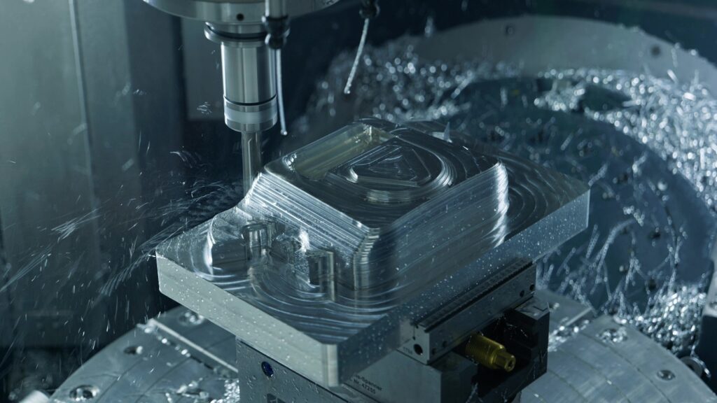
“Machining the core and cavity mold blocks was surprisingly easy. It involved a combination of 3- and 5-axis machining, with some of the new Geodesic and Swarf Finishing toolpaths that have been added recently. The results are impressive. The machine motion was buttery smooth which gave a great surface finish.”
—Josh Reader, Manufacturing Engineer, Autodesk
Reader and Aguirre worked together to program both the core and cavity mold blocks. The cavity mold did not contain any slots or challenging features and so could be produced with CNC machining alone – no need for EDM.
Adding the finishing touches with EDM
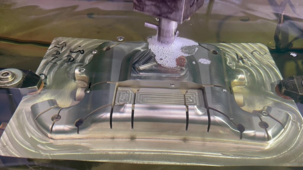
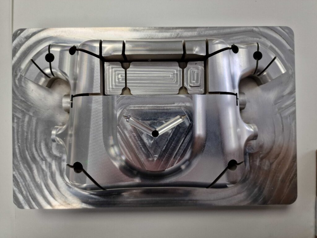
At a very early stage, Reader realized that the core mold block would need additional processing. It contained features, like deep slots and sharp internal corners, that were going to be impossible or impractical to produce via CNC milling. The decision was made to leave these features un-machined and produce them using electrical discharge machining (EDM).
Fusion’s solid modeling tools were used to create 3D models that represent the forms that were to be “burned” into the tool via EDM.
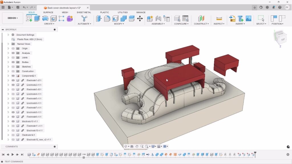
The electrode models (shown above in red) were securely shared with a local supplier who was tasked with manufacturing the electrodes and using them to “burn” the features into the previously CNC-machined core mold block.

The supplier produced a family of electrodes in graphite and copper, with each one consisting of key elements:
- The 3D shape of the slot/rib to be “burned”.
- Extension geometry to provide clearance during EDM.
- A rectangular base to load the electrode into the EDM machine.
- Datum information to accurately position the electrode relative to the core mold block
The die sinking process was then used to “burn” the electrodes into the core block, forming the required features.
Leaning on the supply chain
While many of the component parts were produced by the Autodesk team “in-house”, capacity issues meant some of these parts were outsourced to approved suppliers. We would like to thank the following organizations for their support.
- Nerc Precision Engineering Ltd – producing shifter paddles components
- One Click Metal – producing additional 3D printed chassis
- Xometry – producing multiple internal components and switchgear
- A&M EDM – producing the electrodes and subsequent EDM die sinking
- Eurocircuits – producing the printed circuit boards
Bringing it all together
The breadth of Fusion tools that the team leveraged, from design to manufacturing to data management, culminated in a successful project. “At the start of this project, the team wanted to test Fusion to see just how well it supported the end-to-end development of a real-world consumer product,” says Christoper Derdak, Autodesk Technical Specialist and project lead. “I was pleasantly surprised at just how well Fusion was able to meet the design and manufacturing needs but what impressed me the most was how the collaborative tools in Fusion allowed the team to work together. I cannot wait for us to showcase the finished steering wheel at the Hannover Messe show in April 2024 and look forward to seeing how our current and future customers react.”
Check out these resources to learn more:
Learn how you can make amazing consumer products with Autodesk Fusion
Connect your team with cloud-enabled collaboration in Fusion