& Construction

Integrated BIM tools, including Revit, AutoCAD, and Civil 3D
& Manufacturing

Professional CAD/CAM tools built on Inventor and AutoCAD
17 min read
v.2.0.3481
We took care of some hot-ticket items and wanted to get these fixes out to you as soon as possible. This update includes:
v2.0.3470
[toc]
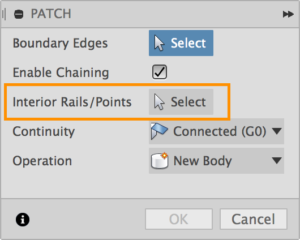
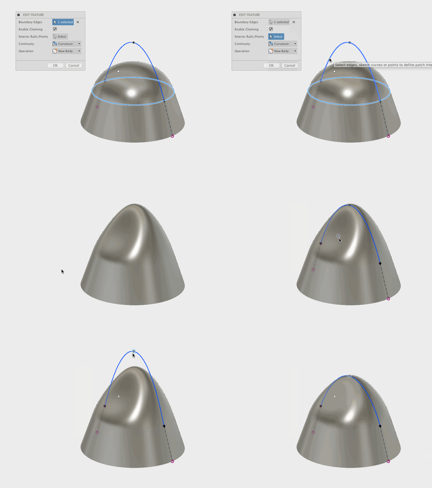
Previously when you tried to create a patch surface in the Patch workspace, there was no way to control the inside/interior of a patch and make it follow a curve or point. Now when you create a patch, there is an option to select interior internal rails/points for the patch surface to pass through.
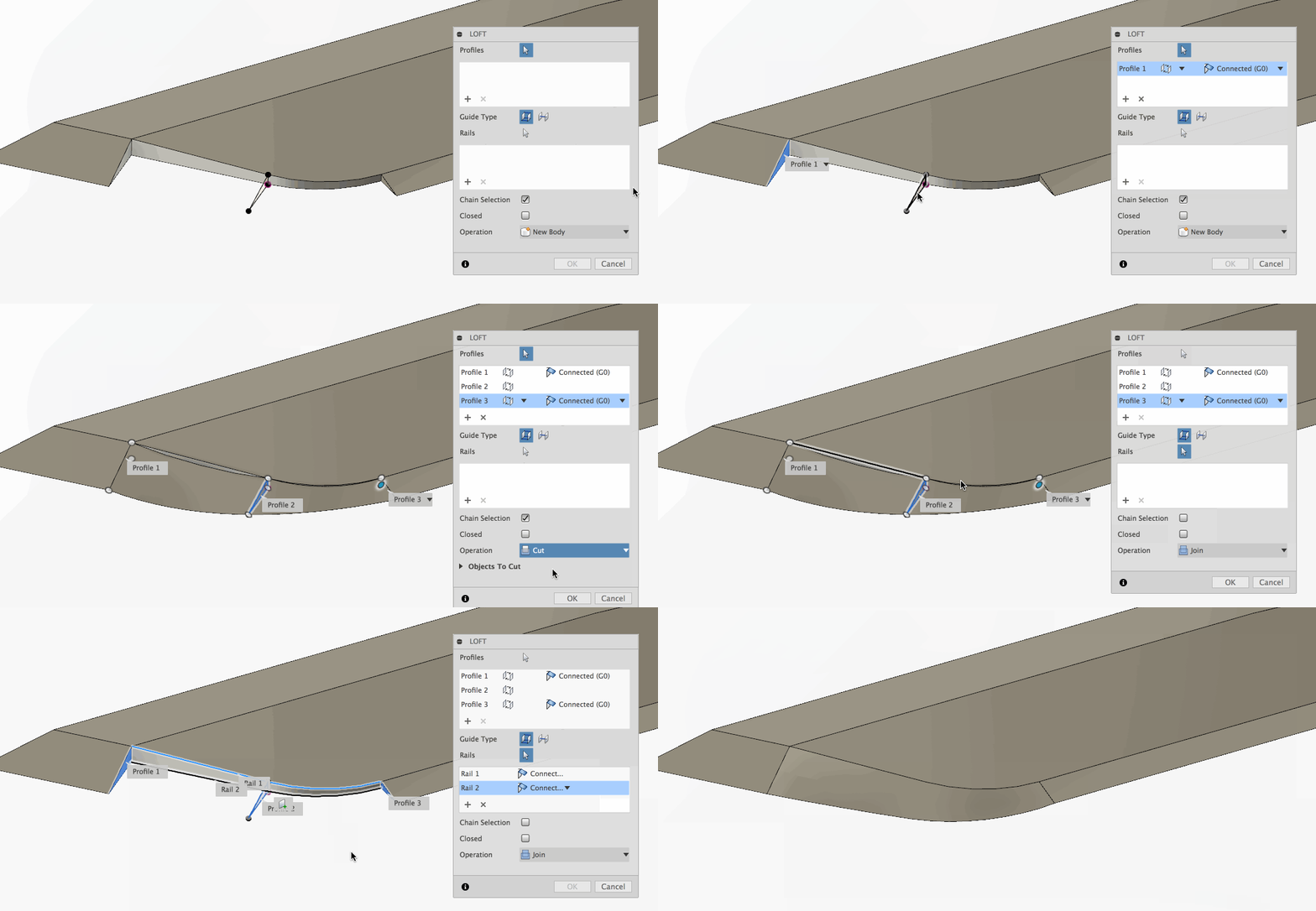
Here’s another great improvement to how Fusion 360 handles lofts. We all felt the frustration when you tried to loft a profile and got stuck because Fusion 360 didn’t allow you to pick edges of solid geometry as rails. Well guess what? Now you can! Check out this example above 
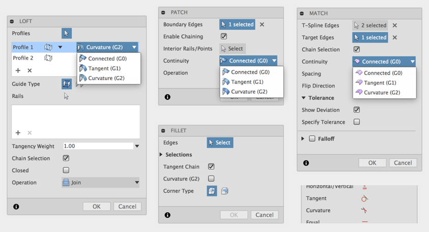
Yeah, this was our bad. Apparently G0, G1 and G2 continuity settings had different names in different commands. Sometimes we called G2 “smooth”, sometimes we just called it G2. Now we made it consistent across the software, so whether you’re in Loft, Patch, Fillet, or a T-Splines tool, you’ll see the same naming convention for curvature continuity: Connected (G0), Tangent (G1), and Curvature (G2).
We were able to fix a number of sticky crash issues related design workflows.


In the last update, we added the the Simplify workspace in Simulation and it has enabled you to modify, simplify and refine your models for Simulation. Now when you make a significant design changes to improve the performance of your design, you can capture these changes and export it as a new Fusion 360 design. Simply right-click on the assembly node and select “Export”. You’ll get the option to save it as a copy in a different project or export it locally as a back-up.
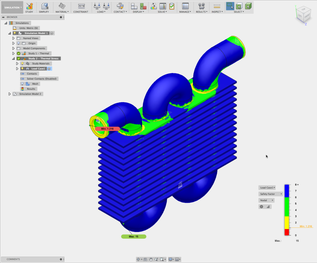
Previously, Fusion 360 was doing some funky math and wasn’t calculating the Safety Factor results correctly when temperature-dependent materials were used, as it was not looking up the Yield Strength for the material properly correctly and the results were coming back as zero. We fixed the error and now Safety Factor results are calculated correctly based on the Yield Strength of the material at the resulting temperature.
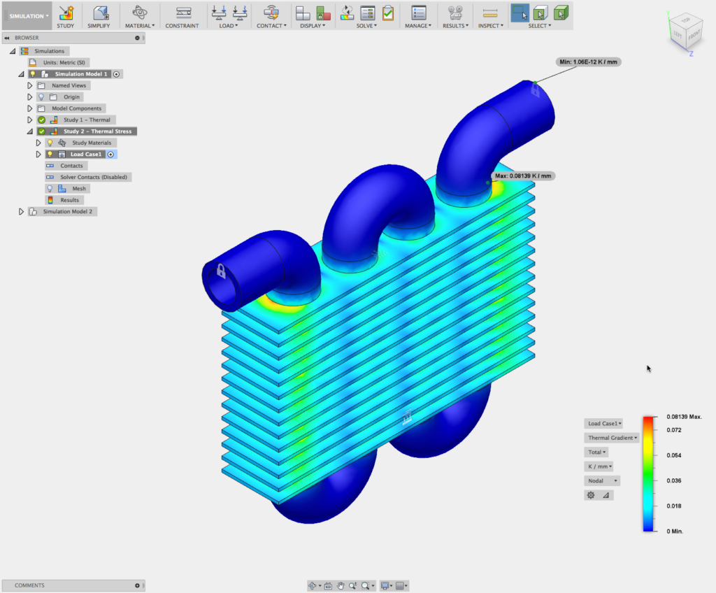
If you’ve been using the Thermal stress and Thermal studies back-to-back, you’ve probably noticed that the Thermal Gradient result type wasn’t showing Thermal Stress study, whereas it was showing in the Thermal study. Not sure why there was this inconsistency, so we got it sorted out and now the gradient is available in both studies.
The beauty of working in Fusion 360 means that when you make a change to your CAD design, you can easily update your CAM toolpaths, Simulation studies, and 2D Drawings associated with that design. Apparently, component name changes weren’t been tracked and thus were not being updated when you hop over from Model to the Simulation workspace. Now it’s correctly hooked up.
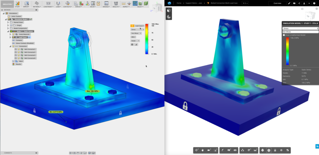
Now when you’re viewing a simulation study via the Fusion Team web viewer, bolted connections and rigid links now show up as they should, so you no longer have to go around asking yourself (or your team) whether there was a bolt there or not.
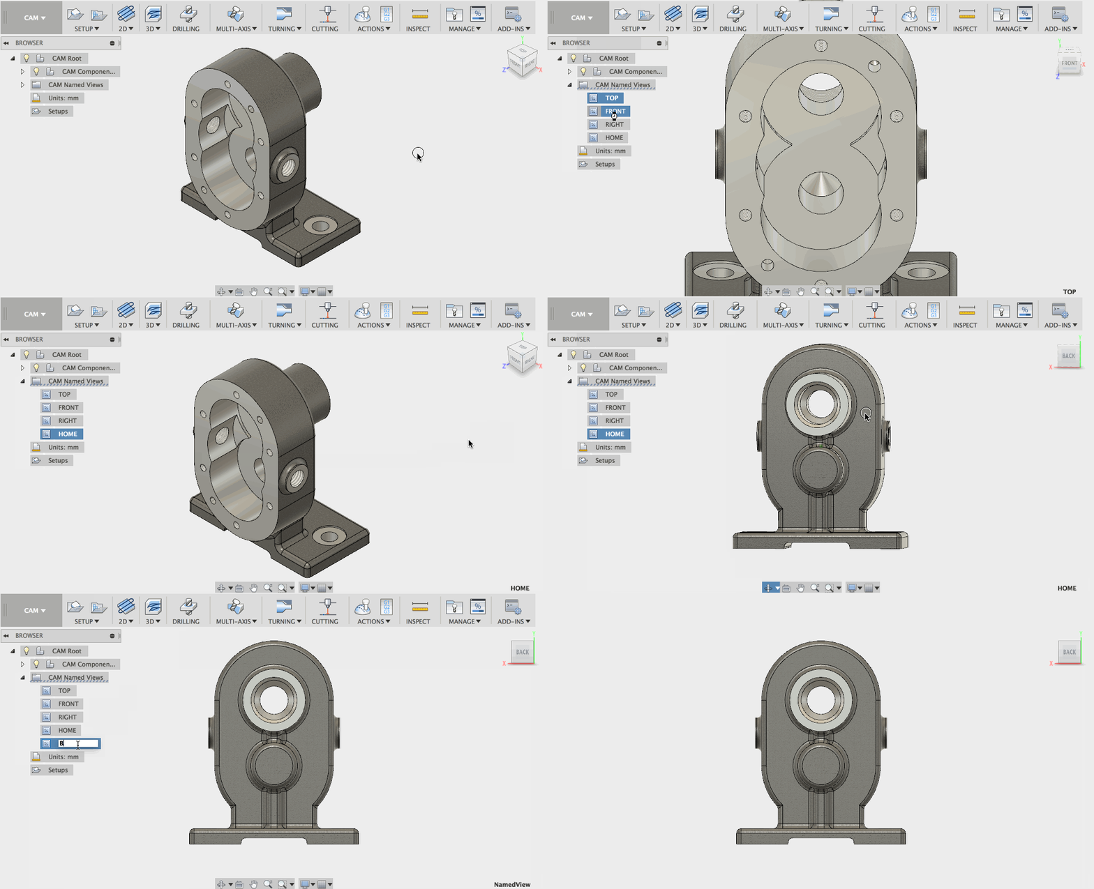
From Chuck now available in secondary spindle operations
We’ve added “From Chuck” to secondary spindle operations for turning.
Parametric confinement for turning face and part
We’ve updated what used to front/back offsets confinement for face and part turning with a new parametric confinement setting, so that changes don’t have to be manually updated.

Why? Two words: time saver. The templates you create for your 2D drawings can now include base view, projected views, parts list for assemblies/single component, and bend table placeholders for folded part/flat patterns as part of the template, and will auto-populate an entire sheet-set based off of the information in your design.
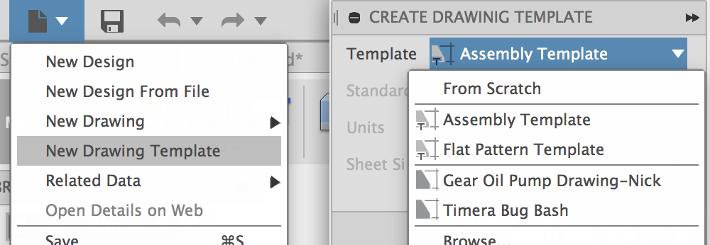
Create a new template by selecting the “New Drawing Template”. You can create a template from scratch, or build off of any other existing templates you have saved in your project.
Once you’re in the newly created template, place a base view to get started. Make sure you select the correct representation for your template. The representation will be the “smarts” that pulls in the right design asset to auto-create all those views on any given sheet.
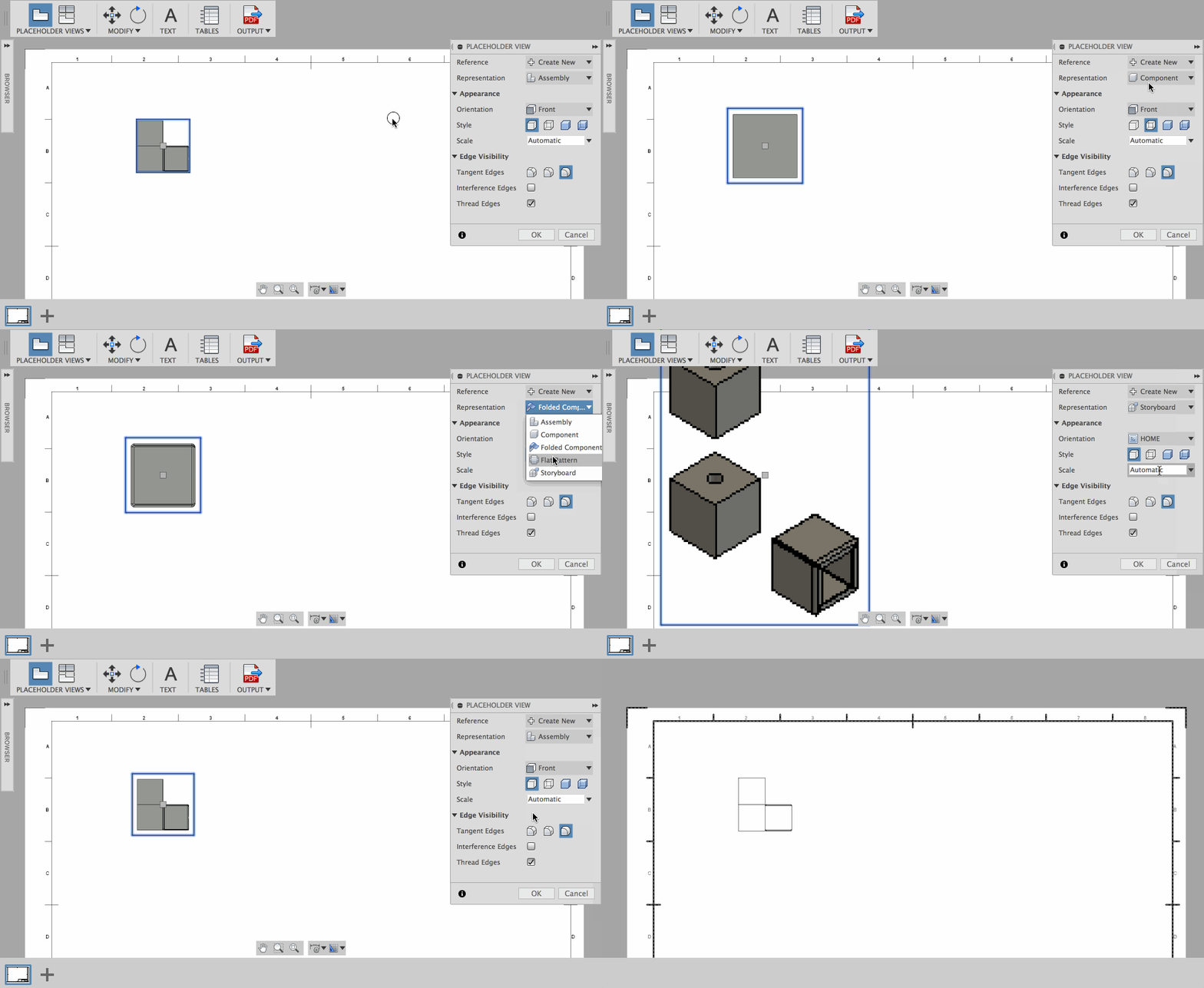
For example, if you’re creating an assembly sheet drawing, select the Assembly representation. If you’re creating a sheet metal sheet drawing, select the folded component or flat pattern representation. If the base view of a template doesn’t exist in the design , the template will simply skip that sheet and auto-populate all sheets that do have assets.. So, if you have a sheet metal sheet as a part of your multi-page template, and you use that template on a design that doesn’t have any sheet metal parts, you’ll get everything except the sheet metal sheets.
Once you’ve got your template set up, save it to your project. Now when you want to create a new drawing of a design, you can select the respective template as a starting point and watch the base view and related info auto-populate as a sheet set.
Here’s an example of using a multi-page template that contains Assembly, Component and Sheet Metal sheets. Check out how the new template works its way down the browser of the Design and automatically generates the appropriate sheet with the appropriate representations in a jiffy. With the click of a mouse you can now have the basics of your entire drawing package created instantly!
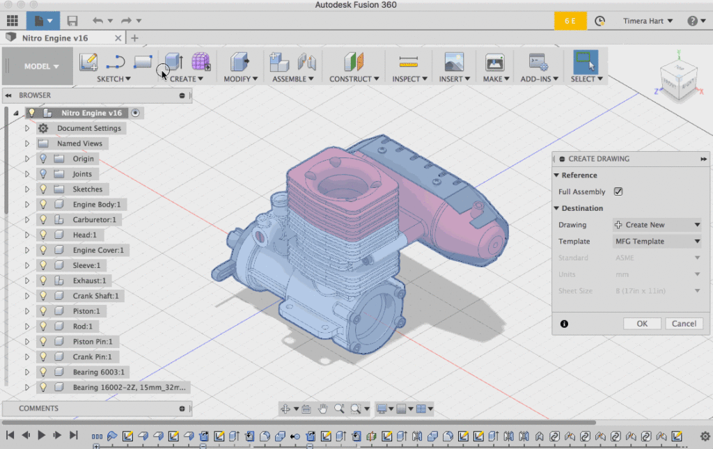
Also, it’s good to know that you can also save any existing drawing as a template and tweak it from there. This way you don’t have to create templates from scratch if you don’t want to.
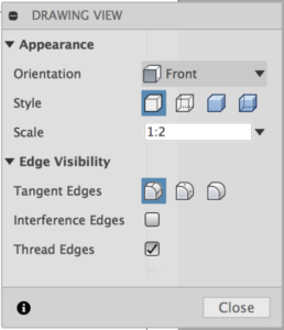
Bonus! Previously, after you placed your Base View, you were locked in to that orientation, which was really inconvenient. As a part of this new template work, we’ve included the ability to change the orientation of any base view after it’s been placed (both in Templates and in any Drawing). Just double-click on a base view to launch the Drawing View dialog and you can switch it right there – also any projected views created from that base view will appropriately update their orientation. Pretty cool stuff.
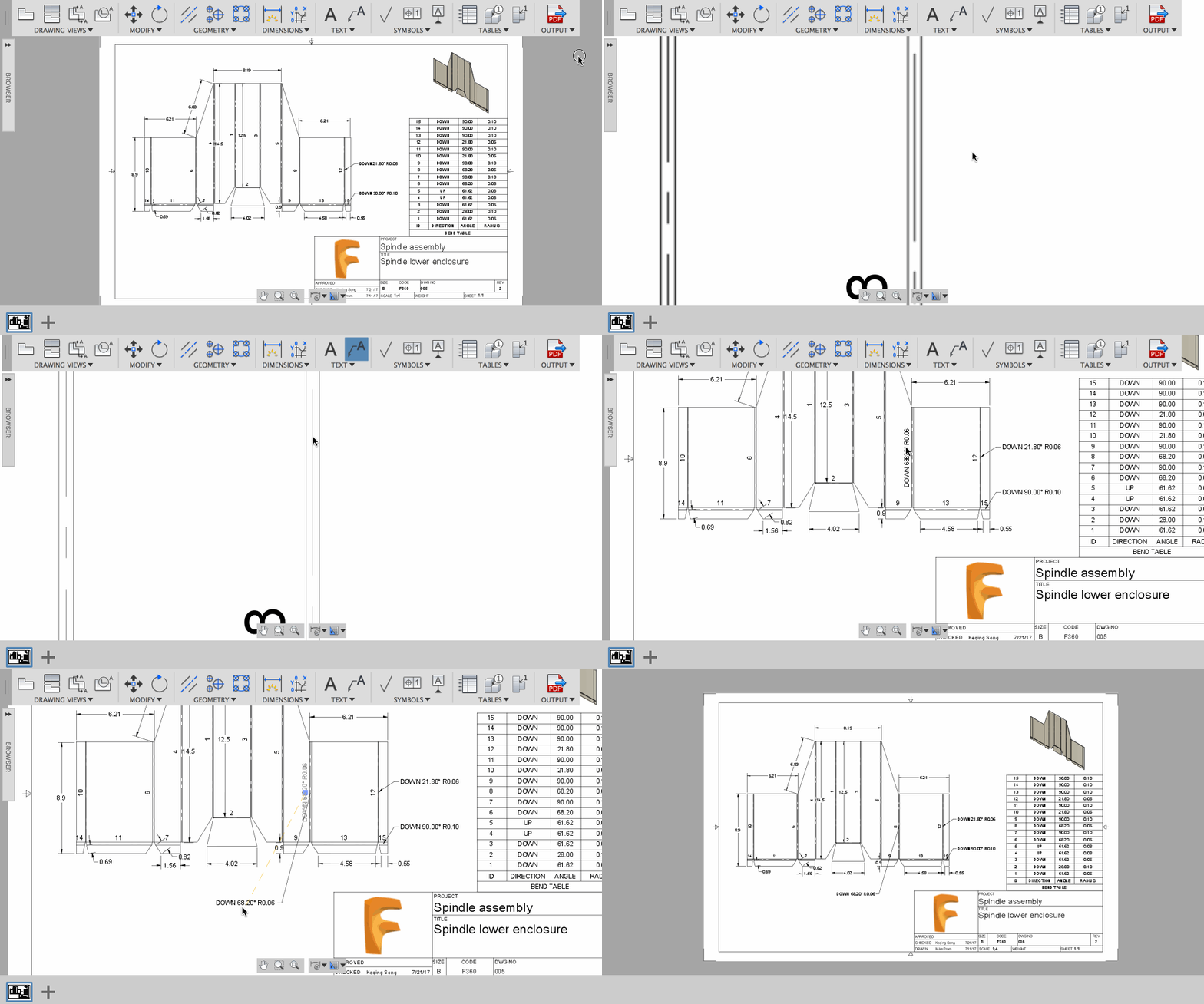
Placing a leader note on a bend centerline will now give you the respective notes: direction, angle, and radius, making it easier to glance at a bend and know exactly what’s going on with it. Double-clicking on the text will allow you to modify the note with familiar text editing tools.
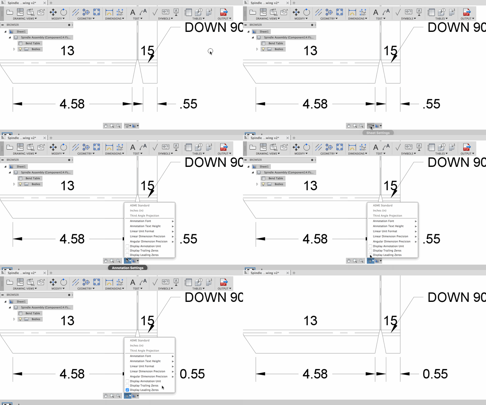
Under the Annotation Settings, you’re now also able to display/hide leading zeros. There’s really not a standard to conform to here, but general best practices suggest to use a leading zero if the decimal is less than 1 since the decimal may be hard to see at a glance for some. It’s really up to you and how you like to document your drawings, but here, you have the option, and this option can also be saved in your templates.
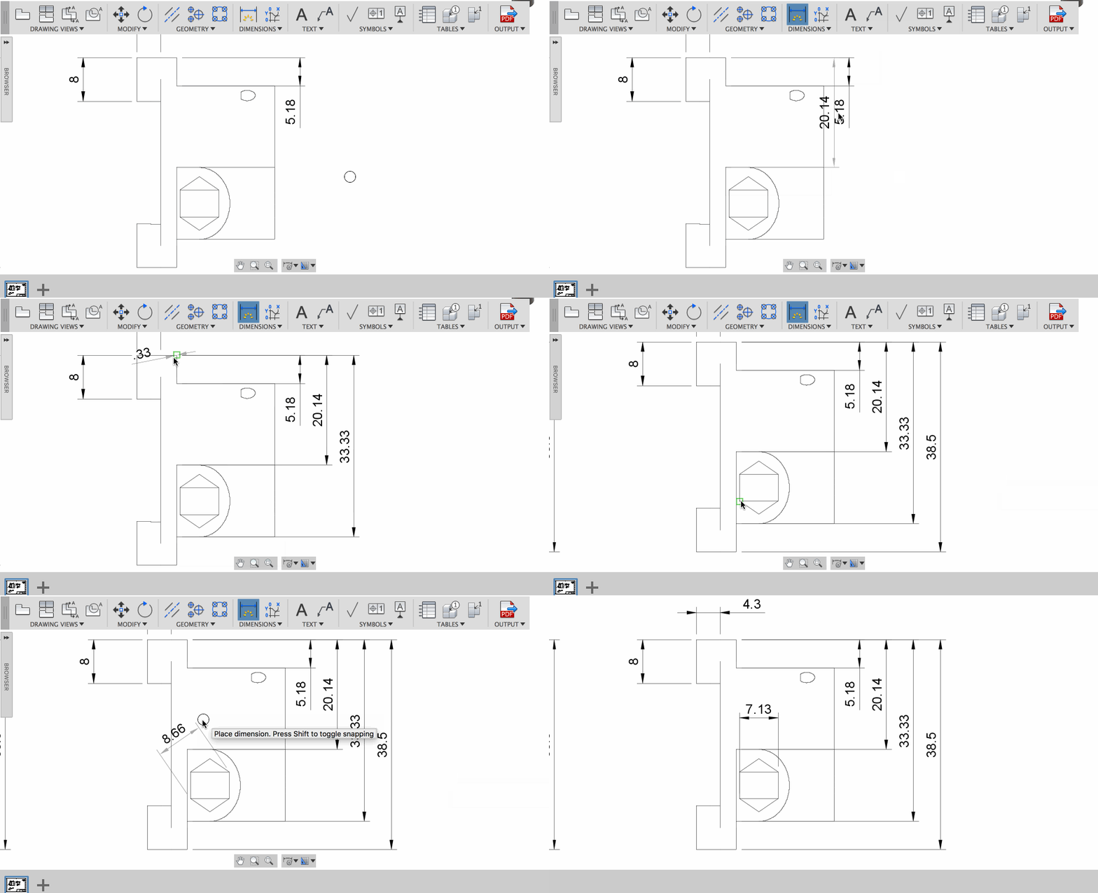
This is nice. Now when you’re placing a dimension, you can also feel it snap to a specific width (defined by the standard) for easier placement and predictable offsets. Also, when you place a dimension on top of another one, it will automatically align them above or below the one it was overlapping depending on which dimension is longer (also to standard). QUICK TIP: If you hold down the SHIFT key, you’ll get free placement and override the snapping behavior.
As a bonus improvement, right-clicking on a dimension before you finalize the placement will give you placement options such as Aligned, Horizontal, and Vertical. Neat!
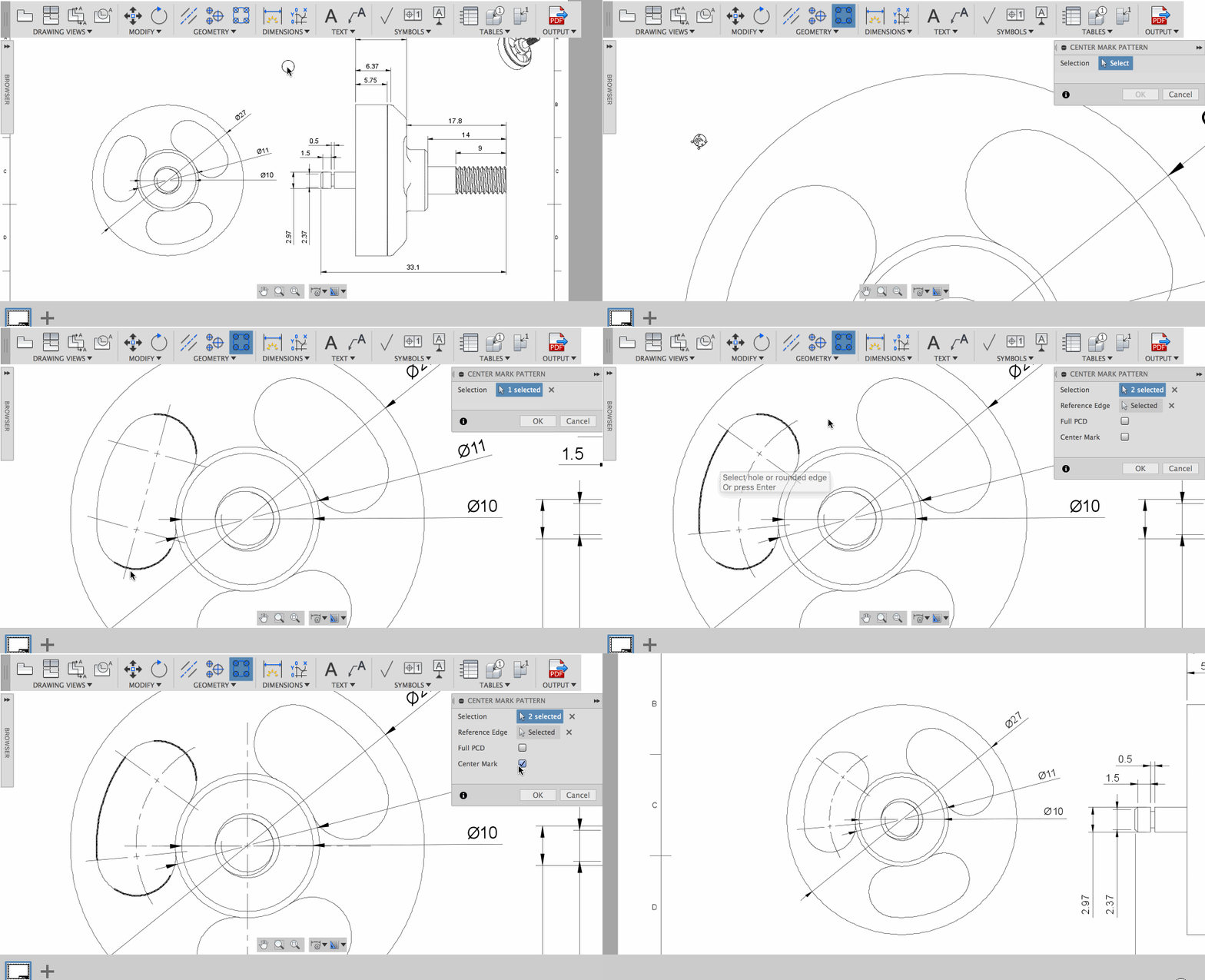
As the tooltip says, Center Mark Pattern lets you select holes, fillets, or the edges of a slot and create a center mark pattern. Supported patterns include full and partial circular patterns, linear patterns and even slots. If you have a curved slot, you can use one of its edges as a reference edge, and the tool will find the centerline of that slot. Toggling Full Pitch Circle Diameter (PCD) will create a full 360 degree circle of that centerline. Toggling the centermark will place a major axis center mark on your pattern, too.
PDF output issue fixed
We got reports of some of you trying to output your multi-sheet drawings as PDF and in return got an error message saying something about an unplottable sheet. We dug into this and found some wonky layer ordering that caused the output to freak out. No worries though, this is now fixed.
A lot of exciting things here, mainly around 3 things: custom graphics, ability to check for changes, and access to CAM machining time. What to know more? Here’s what Brian Ekins has to say.
This is a huge enhancement and is something a lot of you have been requesting for the past couple of months. The Fusion 360 API now supports the ability to draw your own graphics! The API refers to this as “Custom Graphics”. Of course you can draw graphics now in Fusion 360 but you have to follow the Fusion 360 workflows and are limited by what the software supports.
For example, if you want to draw a wireframe box to show the user the bounding box of a selected body, you would need to create a new sketch and then draw lines in 3D space to represent the box. There’s a lot of overhead in creating this geometry and it results in new objects being added to the browser and timeline that you might not want.
Using custom graphics you create graphics directly within Fusion 360’s graphics subsystem. They are displayed to the user and display correctly in relationship to the other Fusion 360 graphics. Another example is if you are creating some type of CAM system. You’ll be calculating the tool paths in your code and then will want to display them to the user and can use custom graphics to do that.
Custom graphics are not limited to drawing lines but also support the ability to draw triangles and higher level geometry types like circles, arcs, ellipses, splines, and B-Rep bodies. More information about custom graphics is available in the Using Custom Graphics user manual topic and several sample programs have also been added to the help.
We’ve also added support for a new property supported by three different objects that can provide some powerful functionality. The property is called “revisionId” and is supported by the Component, BRepBody, and Sketch objects.
The property itself is very simple. It returns a string, but that string changes every time the object you got the revision ID from is edited. This lets you build some intelligent updating into your programs. If you’ve written a program that draws some geometry based on a selected sketch and whenever that sketch is updated you need to redraw you’re geometry, this will allow you to determine if you need to redraw your geometry or not.
When you first create your geometry you can get the revision ID from the sketch and save it as an attribute with the data you’re creating. Later when an update is requested by the user you can get the revision ID from the sketch again and compare it to the saved ID. If it’s the same then there’s no need to update because nothing has changed. If it’s different then something has changed and you can update your geometry.
The same principle applies when using the revision ID with components or bodies. Which one to use depends on what kind of geometry your program is dependent on.
Yup – the new machiningTime property on the CAM object returns a MachiningTime object that provides various machining time metrics, you can keep better track of how much time you’re spending on parts. The more data you have, the better decisions you can make on running more efficient ops.
Much of the work in the latest Fusion Browser was simply making sure everything works as expected. While it doesn’t feel like much, we actually made quite a bit of improvements under the hood. Here are some new options that are available.

There is now a Export option under the file menu – it lets you export your design locally as an OBJ or STL file for prototyping or further editing.
Now when you’re in the Move command, you’ll see the rotation manipulators again. They work just like they would in Fusion 360, allowing you to rotate your designs against an axis. Since the pivot option didn’t work well, we yanked it out and are working on improving it’s performance.

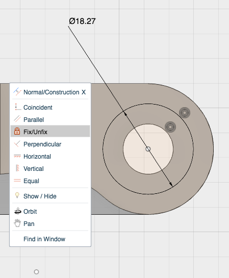
We’ve added basic constraints to the sketch environment. You can now start to lock down your sketches like you would in the desktop experience. Power is nothing without control.
We’re always thrilled to be delivering fresh goodies to you as soon as they become ready n’ steady. With each update landing, we’re already locking down the next one. As always, we appreciate your support and be sure to give us a hollar in the comment section below.
Cheers!
The Fusion 360 Team
By clicking subscribe, I agree to receive the Fusion newsletter and acknowledge the Autodesk Privacy Statement.
Success!
May we collect and use your data?
Learn more about the Third Party Services we use and our Privacy Statement.May we collect and use your data to tailor your experience?
Explore the benefits of a customized experience by managing your privacy settings for this site or visit our Privacy Statement to learn more about your options.