Elevate your design and manufacturing processes with Autodesk Fusion
There’s a lot to learn on the path of Fusion 360 mastery. Whether you’re working on a 3D printed project or a complex assembly, every Fusion 360 design requires use of the Big 3 – The Timeline, Browser, and Preferences. In this article we’ll be walking through the fundamentals of the Big 3 and how to use them effectively in your next design project.
Previewing the Preferences
Fusion 360 offers a ton of preferences to customize your design environment. If you’re coming from another CAD tool like SolidWorks or Inventor then you likely already have an established workflow. A few settings in Fusion 360 can be tweaked to make you feel like you’re right at home. To open the preferences, left-click your name in the top right corner of Fusion 360 and select Preferences.
Pan, Zoom, and Orbit
For existing CAD users, the first setting you’ll want to tweak is the Pan, Zoom, and Orbit shortcuts in the General section. You can keep these at default, or switch them to SolidWorks, Alias, or Inventor.

Design History
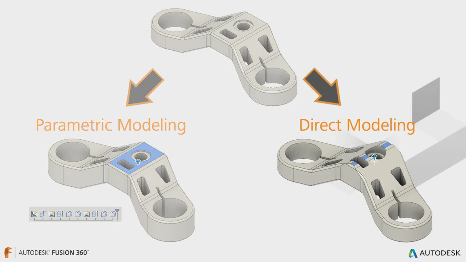
Next up, head into General > Design and take a look at the Design History option. By default Fusion will capture every change made to your design in a tieline. This process is called Parametric Modeling and is great when you need to capture specific features and define the relationship between parts.

Turning off design history allows you to work in a Direct Modeling environment. This lets you quickly create geometry without having to worry about individual features.
Which one is better, Direct or Parametric Modeling? That depends on your specific design needs. Keep these thoughts in mind:
Parametric Modeling is great for designs that require exact requirements and manufacturing constraints. For example, you might be working on a family of products that all share the same core design but have slight variations in individual features. Activating the design history in this situation would be useful so you can quickly edit individual features.
Direct Modeling is more suited for designers that just want to create geometry without worrying about the features and the manufacturability of a design. For example, if you’re just working on a conceptual model then you might not care about the connection between individual parts and just need to define faces.
https://help.autodesk.com/videos/RpazVtMzE61vLqiAewdnV8bfnelWqJHp/poster
The difference between Parametric and Direct Modeling really comes down to relationships and details. Do you care about how one part relates to another in an assembly? Go with Parametric Modeling. Just want to deal with faces and geometries? Direct Modeling will do.
Feature Preview
Fusion 360 is always getting new features and enhancements, that’s what our customers love about it. When we’re baking new features in the development kitchen you can try them out in the Preview preferences.
Select Preview at the bottom of the Preferences dialog and you’ll see all of the new features in development. Tick one of the boxes and you’re ready to use it.

Keep in mind that these features are conceptual in nature and are still being actively developed. Some of them might make it to prime time, others get pulled for rework. If you find a bug, we’d really appreciate your feedback.
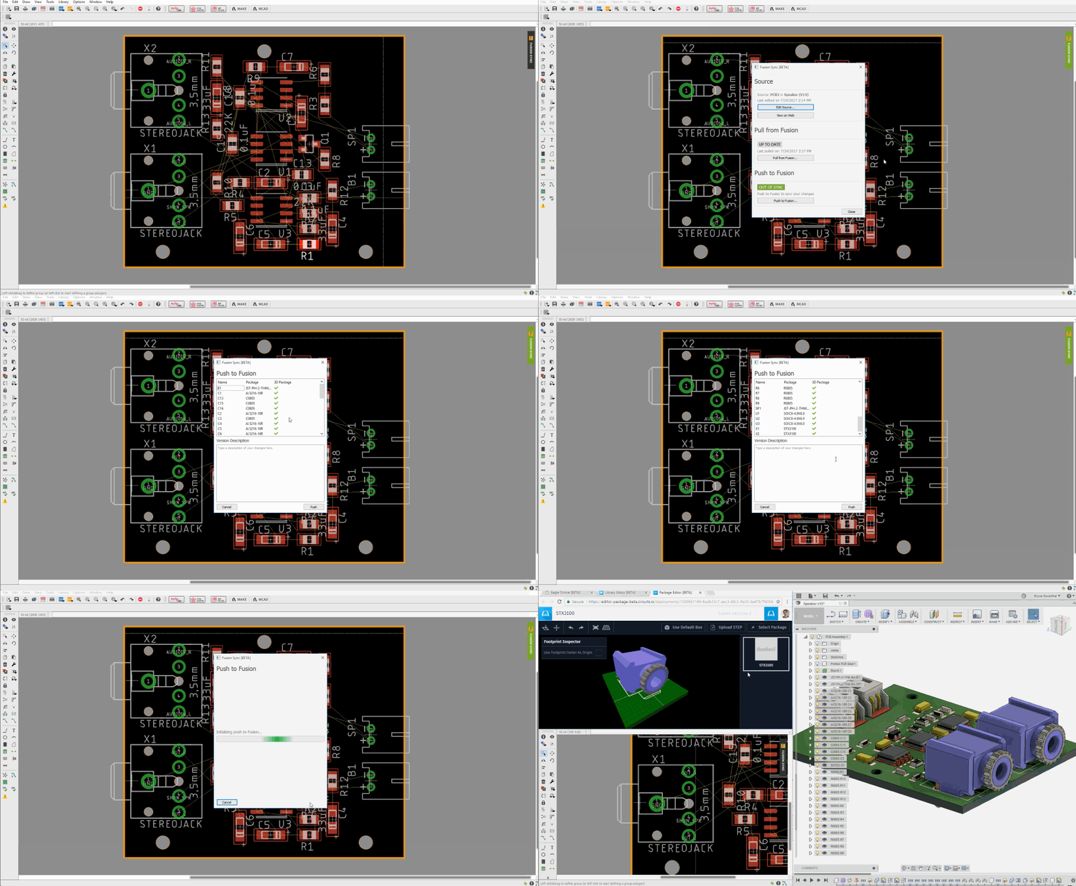
P.S. Do you work alongside an Electrical Engineer in EAGLE? The PCB Feature makes it easy to connect electrical and mechanical designs together between Fusion and EAGLE. Give it a try!
Browsing the Browser
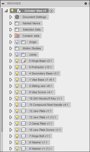
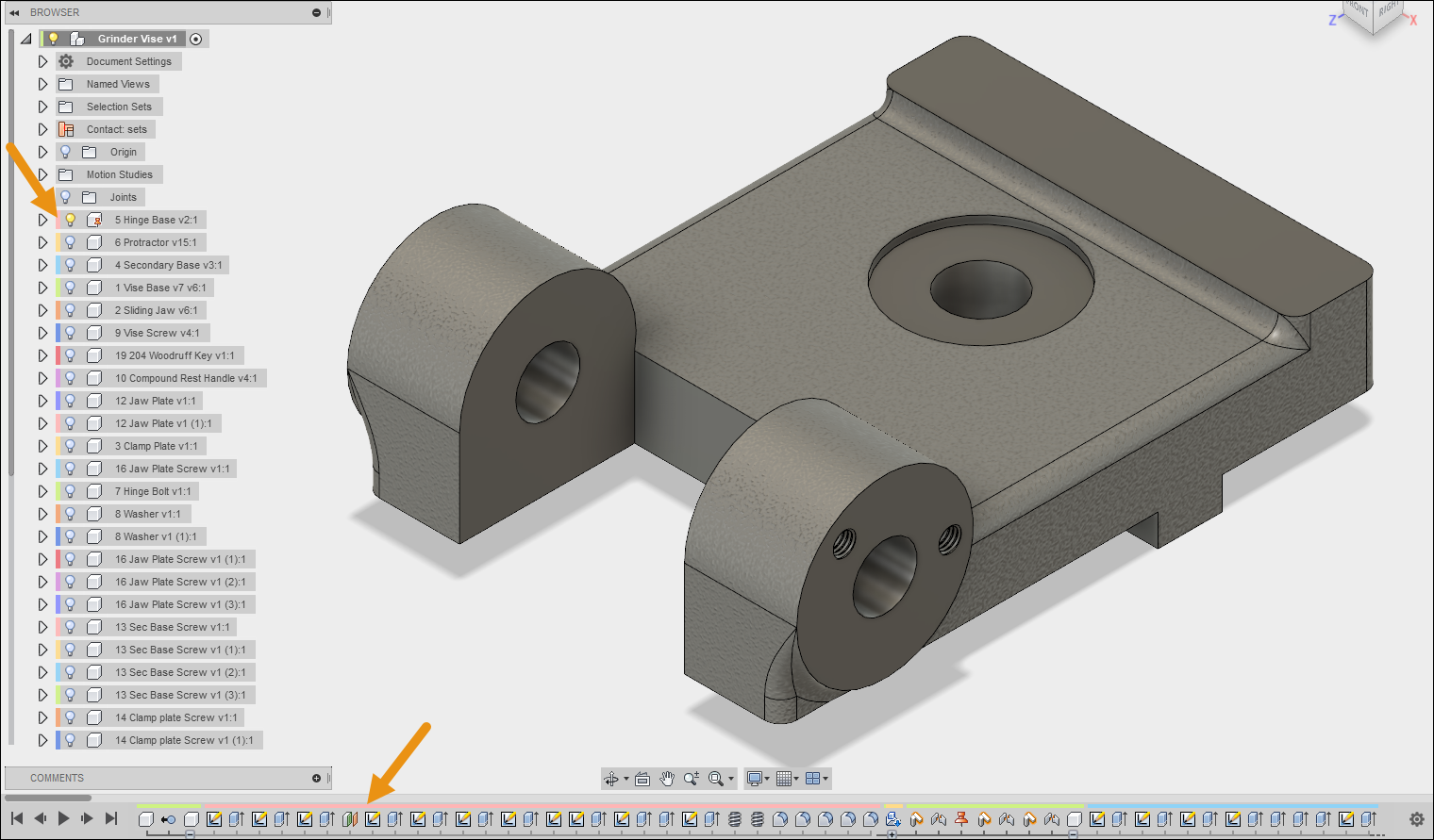
The Browser is where every piece of your design lives. Whether that’s a specific feature, sketch, origin plane, component, or body, it’s all here. As you can see in the image below, the Browser is organized in a tree-like structure. The top-level entry is the primary Grinder Vise assembly with several sub-folders nested inside.
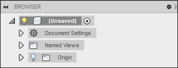
The Browser above looks a little crazy, but open a new design and things start off simple. A new Browser will have three folders – Document Settings, Named Views, and Origin.
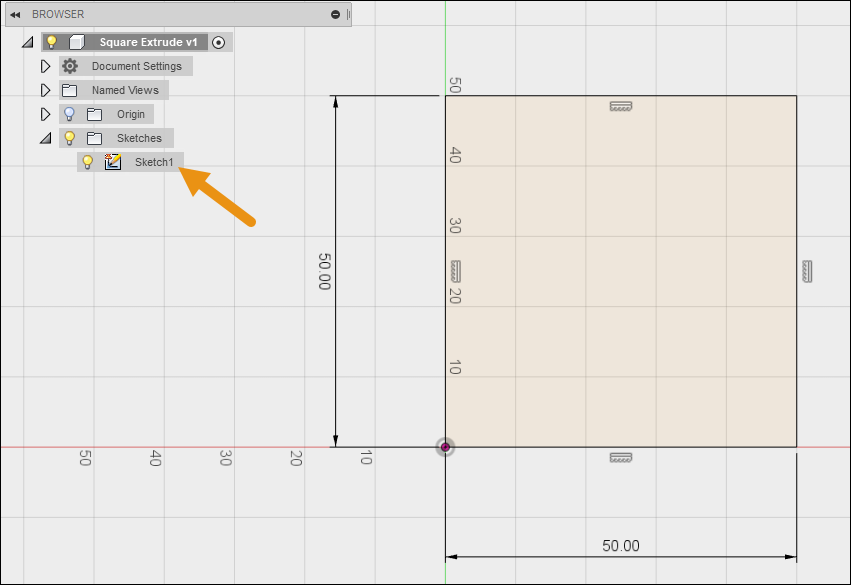
When you add a new feature to your design, it will automatically get added to the Browser. For example, if we add a simple sketch of a square this automatically gets added to the Browser under a Sketches folder.
Extrude that sketch into a cube and a new Bodies folder is created.
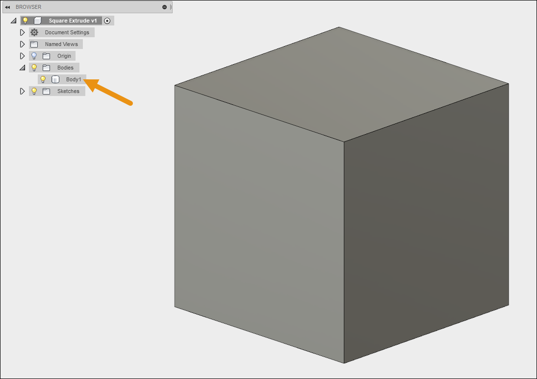
This simple yet powerful process of organization will happen 24/7 as you work on your design in Fusion 360. You don’t need to worry about what goes where, the Browser will handle that for you.
Let’s take a look at some of the default Browser folders in more detail.
Named Views
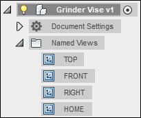
The Named Views folders contains several default views that shift the perspective of your design. You can also create your own custom views and add them to this folder.
Active Units
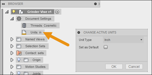
Expand Document Settings and you’ll find Units, which sets the default unit type for your design. To change this setting, hover over Units and select the icon that appears to the right.
Origin
The Origin folder contains all of the available planes, axes, and origins that you can use to create new sketches on. One thing to note is that this folder is connected to the main assembly of your design. When you create new components each component will also have its own unique origin folder.
For example, in the image below you can see that we have a top-level Origin folder as well as another Origin folder within the Hinge Base component. Both of these origins are independent from each other.

Origins are not displayed by default. If you want to see them in your canvas left-click the lightbulb icon next to the origin name.
Components
Components are the last major piece of the Browser puzzle. These design objects have two important jobs. First, they can serve as containers for a variety of design features. For example, the Hinge Base component below, identified by the block icon, contains its own origins, bodies, sketches, and construction geometry.
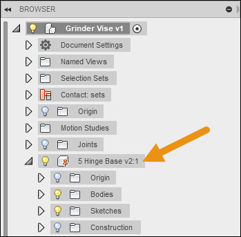
Some engineers prefer to outline the structure of their design first with components, and then add sketches and bodies to each component.
Components, when combined with joints, are also capable of motion. This makes them perfect when design assemblies with moving parts.
You can work with components in the Browser by first activating them and then adding features like sketches and bodies. To do this, hover over a component’s name, then select the radial icon to activate it.

After activating a component a couple things change. First, your canvas grays out every other feature except the component you have activated. Second, the timeline at the bottom changes. This new timeline shows features that are specific to the activated component.
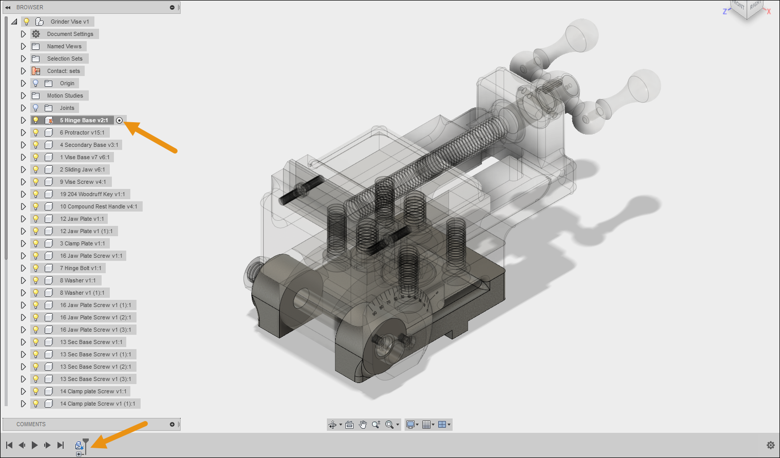
There’s a lot more details to cover about working with components. While we can’t cover them all in this article, keep these points in mind:
- Every component has its own part name, number, and description that will show up in a parts list.
- Components are like stand-alone features that can be quickly reused across multiple design projects.
- Using the Paste command to duplicate a component will create a connection between the original and copied component. Change one and it will change the other.
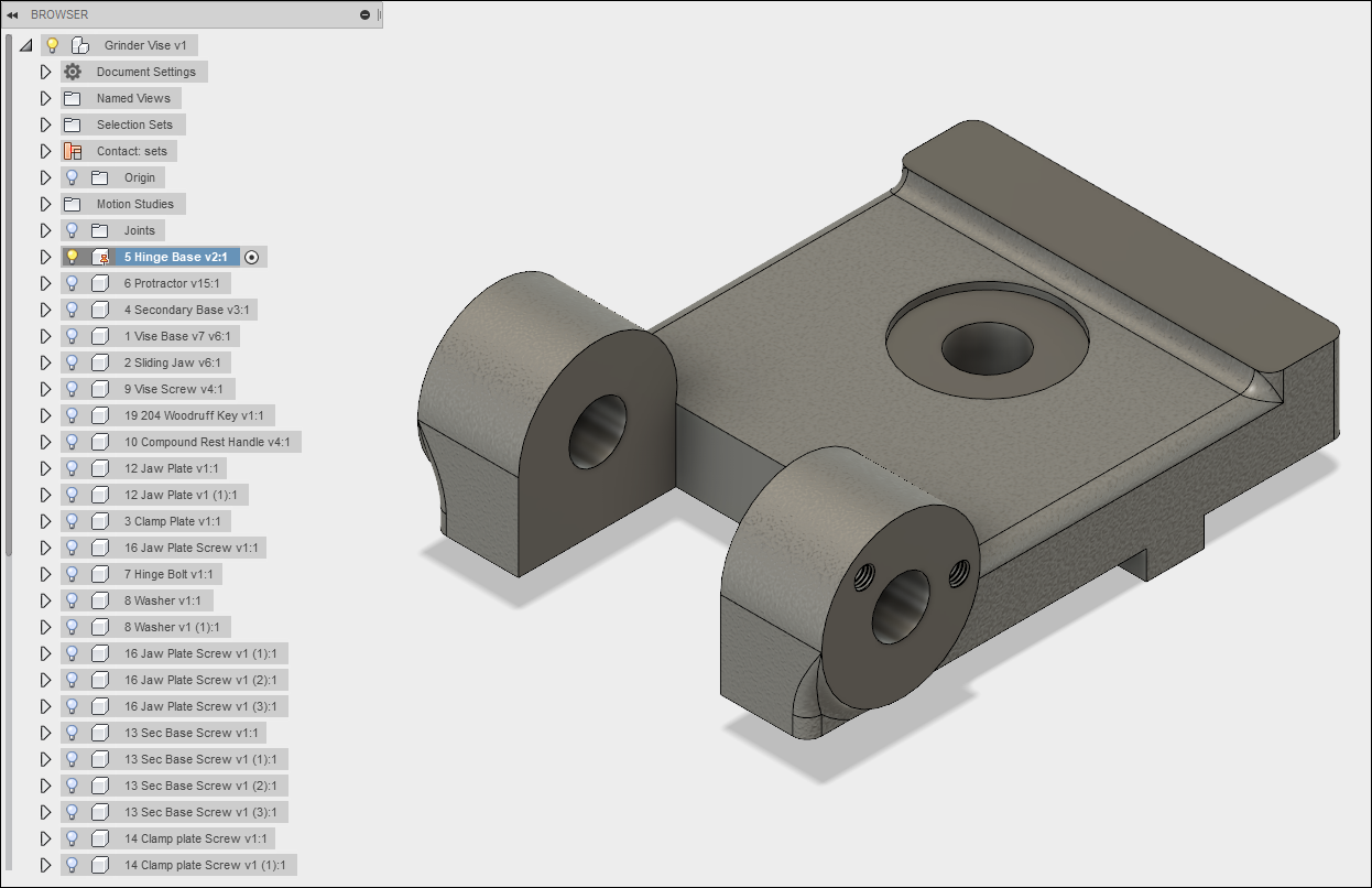
One final note about components, you can use the Isolate option in the Browser to just display the part you are working on. This is great for decluttering a complex assembly. To isolate a component, right click its name in the Browser and select Isolate. Now your view is all cleared up.
Traversing the Timeline
The Timeline is located at the bottom of your Fusion 360 interface and contains a complete collection of every change made to your design. If you ever want to know what happened and when, this is the place to look.
Timeline Navigation
Left-click any Timeline entry and you’ll see it highlighted on your design. You can also use the left and right arrows to the left of the Timeline to roll backwards and forwards in time. This can be great for troubleshooting geometry issues or rolling back changes.
![]()
When you add a new feature to your design, it gets automatically added to both the Timeline and Browser simultaneously.
Timeline Settings
To the right of the Timeline are some handy settings. You can turn off design history entirely from here, which will put you in a Direct Modeling workflow.
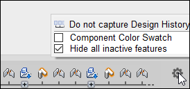
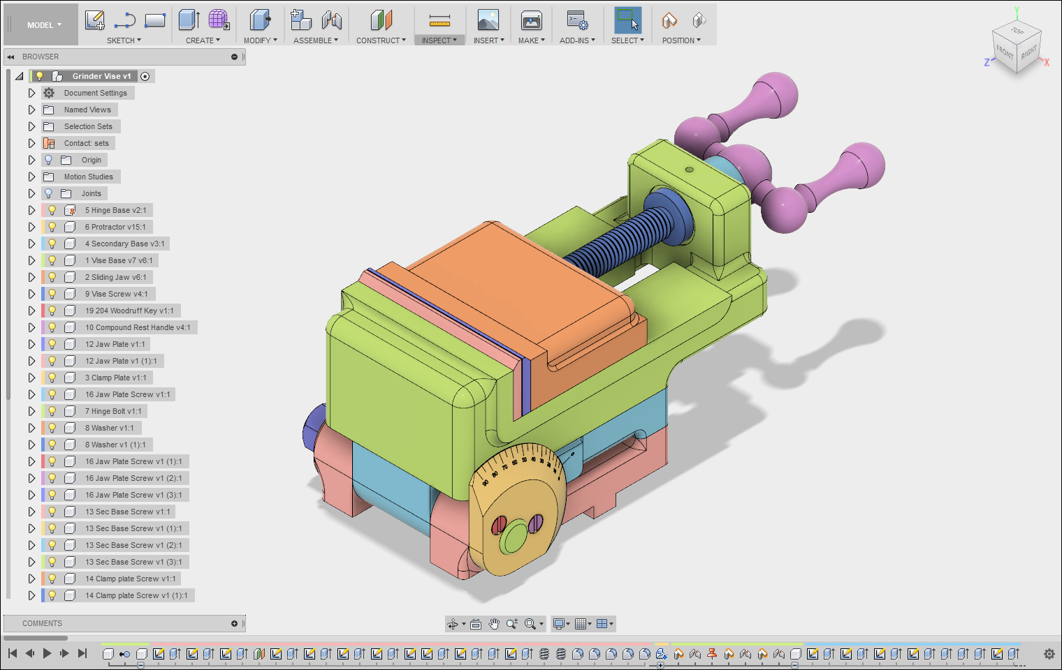
You can also turn on the Component Color Swatch. This will color code entries in your Timeline and Browser. For example, in the Timeline below we can see a bunch of changes made with a pink highlight. Cross-referencing this in the browser shows that these changes are all related to the Hinge Base component.
You can make the color coding even more visible by turning it on for the physical parts in your design. Press Shift + N (Mac), or Ctrl + N (Windows) to turn on Component Color Cycling Toggle. The colors of your parts will now line up with those in your Browser and Timeline.
Grouping Timeline Entries
As your design evolves the Timeline will likely have a ton of entries. An easy way to create order is to group related timeline entries together. To do this, Shift + left-click the Timeline entries you want to group, then right-click the selection and choose Create Group.

Grouped Timeline items will be nested under an icon with three rectangles. Selecting the + icon below this icon to expand the group and show its contents.
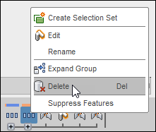
You can easily delete a group by right-clicking it in the Timeline, then select Delete.
Taking the First Steps
Knowing how to navigate the Timeline and Browser will give you greater control and visibility over individual features. For existing CAD users, there are several preferences you can tweak including Design History and Pan, Zoom, and Orbit to make your transition to Fusion 360 easy. Master the Big 3 fundamentals in this article early and it will make the rest of your journey with Fusion 360 easy!
Whether you’re new to CAD or new to Fusion there’s always something new to learn. Keep your knowledge going, try Fusion 360 for free today!