Autodesk Fusion software is one of the most powerful design and engineering tools available on the market. It allows industrial designers and mechanical engineers to design, analyze, and manufacture their ideas. Thankfully, there are plenty of learning resources to help people new to CAD—or just new to Fusion. However, it can be difficult to find more advanced content that shows how to get from an intermediate level to an expert level—how to design and engineer the best products possible and do so more quickly and easily. In this technical session, you’ll learn the most effective techniques to take your product design and engineering skills to the next level and beyond.
If you’re interested in becoming a Fusion design and engineering expert, this is the article for you.
Early decisions with BIG impacts
Your very first step is choosing an origin and orientation. The position and orientation of your part relative to the origin is critical and can determine how easy or difficult your design will be. Changing your part’s position or orientation relative to the origin after modeling history is created is not easy. So, choose wisely!
Next, what axis should face upwards? Keep in mind that Fusion sets the Z-axis by default. If you’re working with another designer and their CAD software is set up to the Y-axis by default, consider doing the same. If you plan on using a CNC machine for your design, you might want to stick with the Z-axis. Note that using joints between origins will allow rotations between these parts along the Z-axis, So, if you do choose to use Y up, you may want to create a Joint Origin at the Origin, but oriented normally to the Y-axis. Jointing to the newly created Joint Origin will allow for proper rotation.
And speaking of the origin, where should it be? Most engineers place the origin in the center of the component. Should the origin be in the center, top, or bottom of the component?
Take a look at the following examples below:

This alignment allows you to easily insert this assembly into a given space, like a room, office, or factory. However, small items that sit on top of the table will require manual alignment.

This alignment allows you to import small items onto the table quickly and easily. However, you will have to manually align this assembly into a space.
Shared vs. individual origins
Next, what is the difference between shared versus individual origins? Shared origins allow you to throw all parts into an assembly more quickly and easily since they will always snap in place. However, the 2D drawings for each part serve as a challenge since parts won’t align to the world coordinate system. Individual origins give you more control over each part and 2D drawing creation is much more straightforward. The trade-off is that part assembly takes more time.
Types of modeling methods
We’ll go over three types of methods: bottom-up modeling, top-down modeling, and hybrid modeling.
With bottom-up modeling you can design each part individually with separate files and assemble all parts in a given assembly. You can also edit individual parts within the context of the assembly. This will give you more control over data, including versions and release states. It will also enable you to work on one component or subassembly within a design at the same time as someone else works on a different component or subassembly of the same design.
It comes with some drawbacks, however. Most notably, it’s slower than top-down modeling. It’s also more difficult to share parameters. Certain features may not be available via Edit in Place. Propagating changes require you to update references.
Next, is top-down modeling. This is when you design all parts together within a single file. It’s a faster method with all the features available to you. Changing one component immediately propagates to all other components. The downside is slowed team collaborative efforts, difficulty controlling data releases, and it’s trickier to re-use a component in another design.
As the name suggests, hybrid modeling is a cross between bottom-up and top-down modeling. Common parts are designed individually via separate files, and then inserted into assembly as needed. Each subsystem of a design is a separate individual file, but custom parts are designed within each file.
Form modeling
You can think of form modeling as sculpting digital clay. You can push or pull any face, edge, or vertex. It’s more of an art form than engineering. Form modeling is also incredibly fast, so it’s perfect for concept ideation. This also means that it’s not parametric. Downstream operations and features can still be parametrically tied to the result of a body created in the Form Workspace.
Using parameters
Parameters allow one value, found in a single location, to affect multiple sketches and features. It can be based on other dimensions or even other parameters. It can use equations and logic.
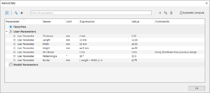
Here are some tips for using a parameter table:
- Use Favorites
- Turn off “Automatic Compute” for files with a lot of parameters
- Can reference existing dimensions by referencing “model parameters”
- Can import parameters from a different file by using Insert →Derive
- Note: Autofill does not work on these referenced parameters; the parameter must be typed in EXACTLY as it appears in the derived design.
Plastic design rules
By applying plastic design rules, you can automate the design of injection mold plastic parts. This makes the design process much faster. Specialty features to automate common requirements for injection molded products include boss, snap fit, lip, and rest.
Finite element analysis
Finite Element Analysis (FEA) saves you from having to make physical parts to then physically test. FEA can tell you if your product is likely to fail or break, where your product is likely to fail or break, and what design is least likely to fail.
What is generative design?
Generative design is a mathematical process that uses computational power to run myriad precise real-world simulations to arrive at a set of optimal design solutions for a defined problem. It relies on algorithms to achieve optimal results, which means that it follows a set of instructions that dictate how it accepts input data and provides output.
Similarly, Generative AI is a type of AI capable of producing novel creations based on pre-trained deep neural networks that produce probable, albeit unvalidated, outputs. Autodesk generative design is a design exploration technology.
Understanding how generative design results are formed
- If a Starting Shape is chosen, Fusion 360 runs an FEA study on your Starting Shape. If no Starting Shape is chosen, Fusion 360 will create one for you by connecting all of your Preserves together and avoiding any Obstacle geometry. Fusion 360 then runs an FEA study on that shape.
- If the stresses are low in an area on the SURFACE of the model, it will remove material (using a strategy dictated by the manufacturing method chosen for that outcome). If the stresses are high in an area on the SURFACE of the model, it will add material.
- It then runs another FEA study.
- Repeat step 2 & 3 until the desired Safety Factor is met OR a fail-safe is triggered.
