[toc]
Generative
Autodesk generative design technology within Fusion 360

You heard all the talk, and now you can walk the walk (at least the baby steps). Right within the modeling workspace toolbar, there will be a “generate” button. Click it and you’ll land on a download page, where the Autodesk generative design installer will begin to download. Install it, and you’ll be able to bring in your Fusion 360 model and run it through our super advanced algorithms to explore a plethora of design variations based on model constraints you set. Even Shuri from Wakanda would be impressed.
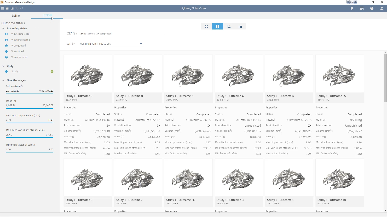
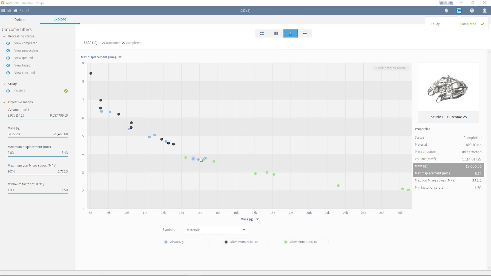
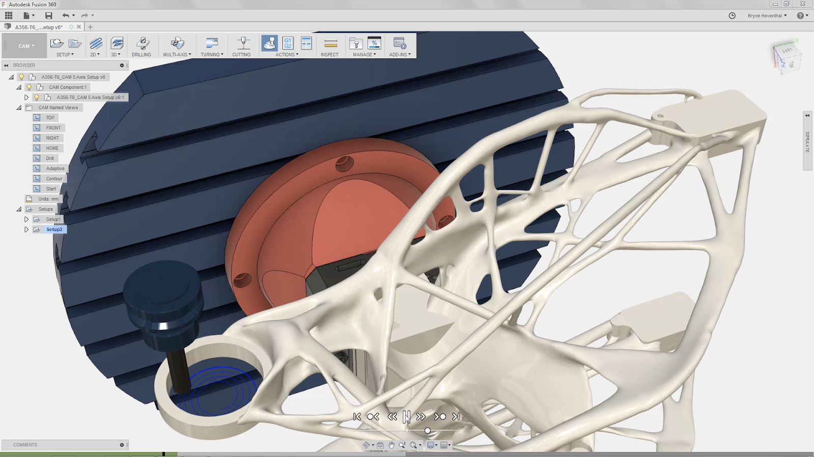
Explore variations visually or on a scatter plot, select the design you want, then bring that model into Fusion 360 and get it made.
You’ll note that the button will only appear for Fusion Ultimate subscribers on Windows OS. If this is something you want to try, subscribe to Ultimate tier of Fusion 360 here. Oh yeah, this is just the beginning. We’re already working on a tighter integration for future updates, by getting rid of the separate install and bringing the technology within Fusion 360 itself. Here are some handy tutorials to help you get started.
Modeling & Sketching
Hole Command Now Has Thread Options
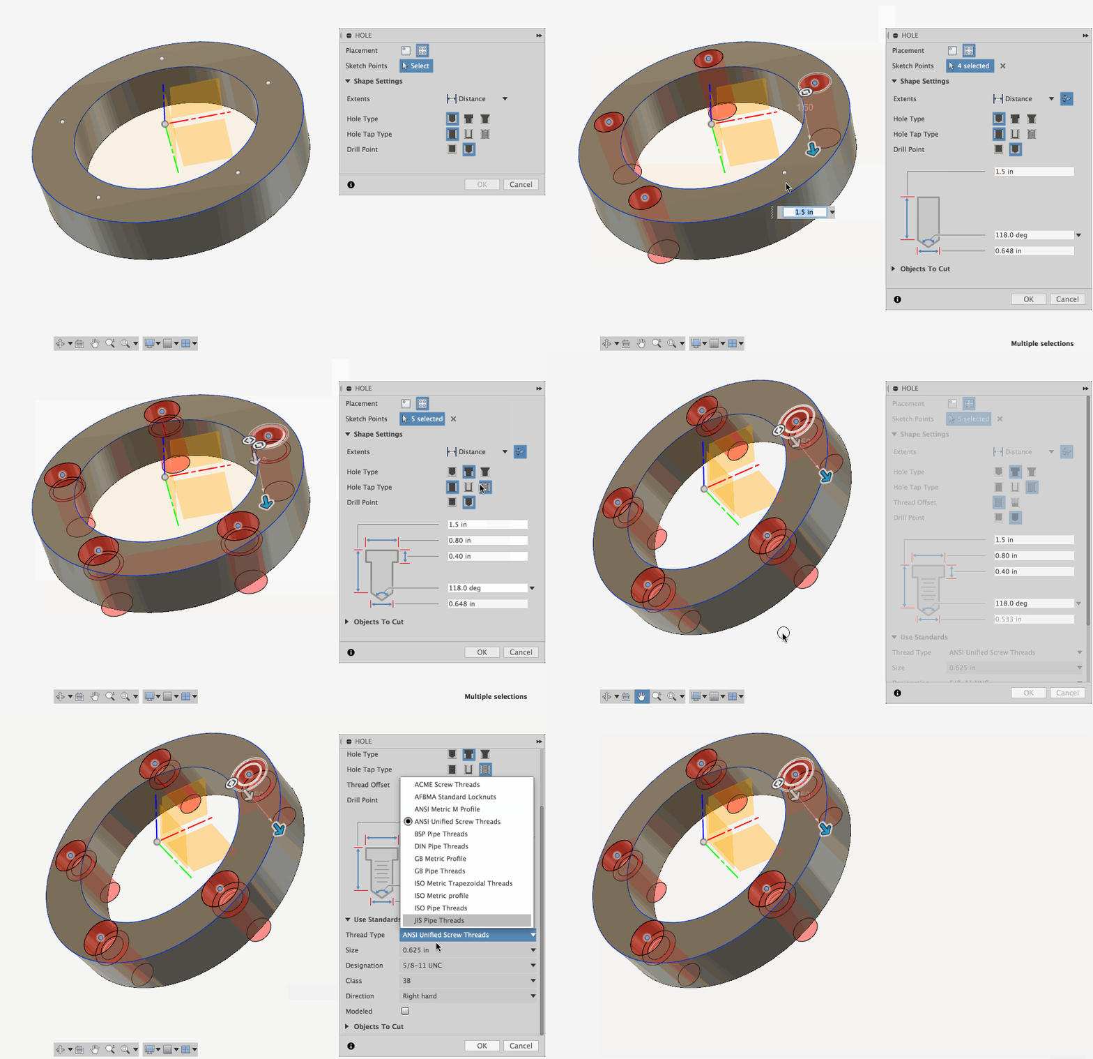
Many of you have told us that you’d like to have the ability to create a hole and thread within the same command, instead of creating them separately in 2 different commands. Yes, we totally agree. Now when you use the Hole command, you’ll have options to thread them, with all of the standard options that come with the thread command. There’s even a nifty visual that shows you exactly what area of the hole you’re changing. It’s also good to know that the Thread command is still there on it’s own, if you need it.
Patch Command Now Has Per-edge Control
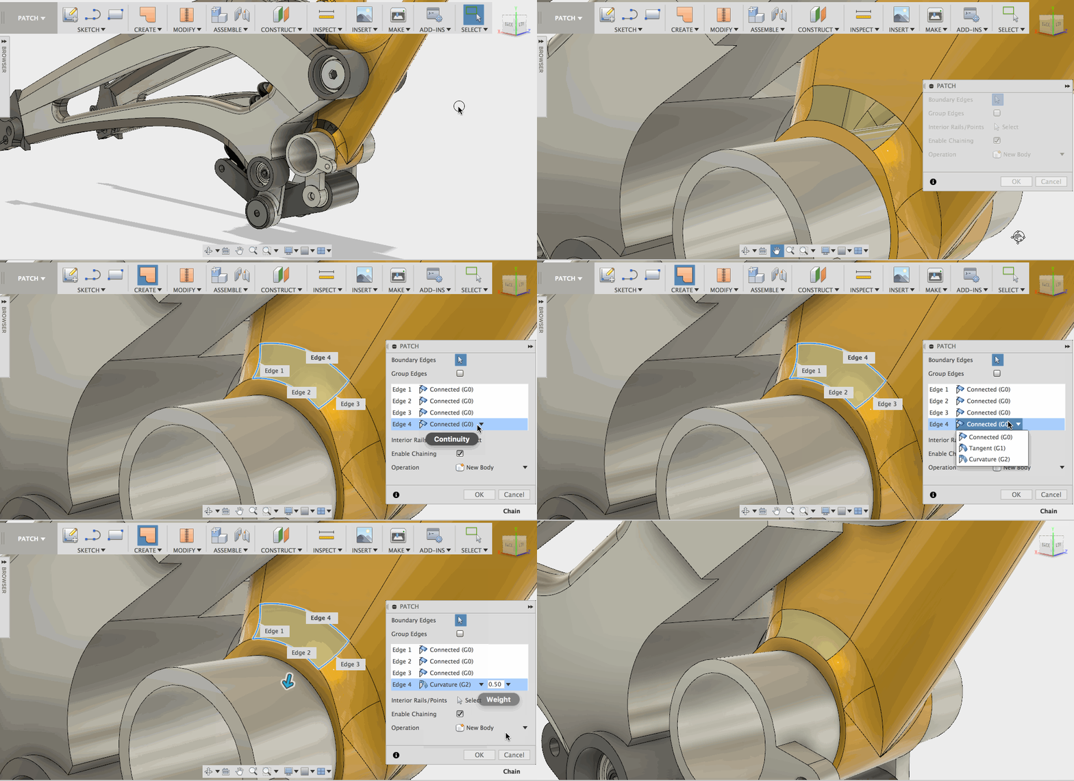
When you’re working with surfaces, there are times where you want an edge to be sharp and there are other times where you want an edge be curved. Being able to control an edge’s curvature continuity is now available in the Patch command. If you have many edges, you can control them one by one or group them all together and set the curvature type you want. Once you’ve set the curvature continuity, you can also give it a specific weight, giving you great control of which edge takes priority.
Sheet Metal Flange Can Now Be Mirrored
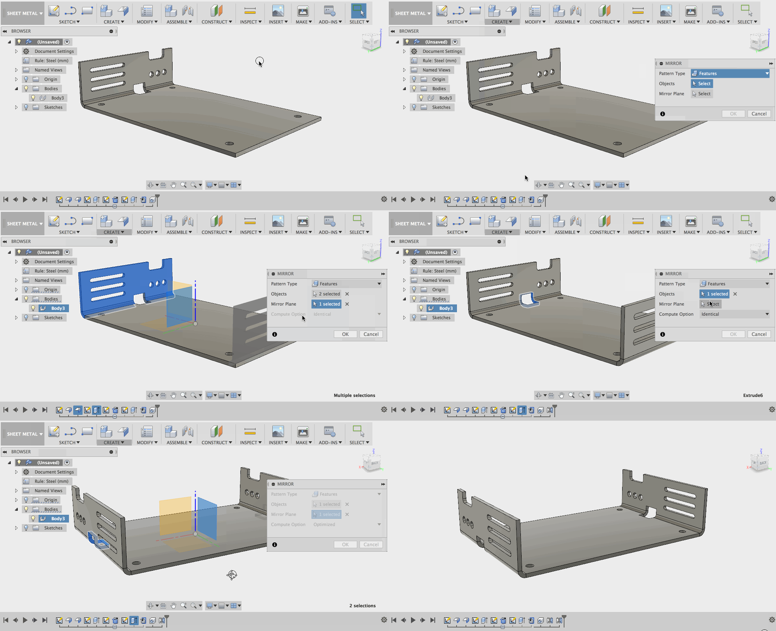
Previously if you created a sheet metal flange and needed to duplicate it to the opposite side because you didn’t want to spend time recreating all the feature work you did to it, you were left with no choice but do recreate it from scratch. Now you can use the Mirror command to mirror the flange and it’s features.
PRO TIP: Pay attention to the order you select your features to mirror. For instance, the GIF above shows mirroring a flange and the extrude cuts. You need to select the flange first, and the extrude cuts second for the mirror operation to work properly. If you’re having trouble patterning associated features along with your flange (especially cuts across bends), you’ll need to do it as a separate Mirror action, and make sure that you have the “Optimized” selected as your Compute Option.
Sketch Text Now has Single Line Fonts
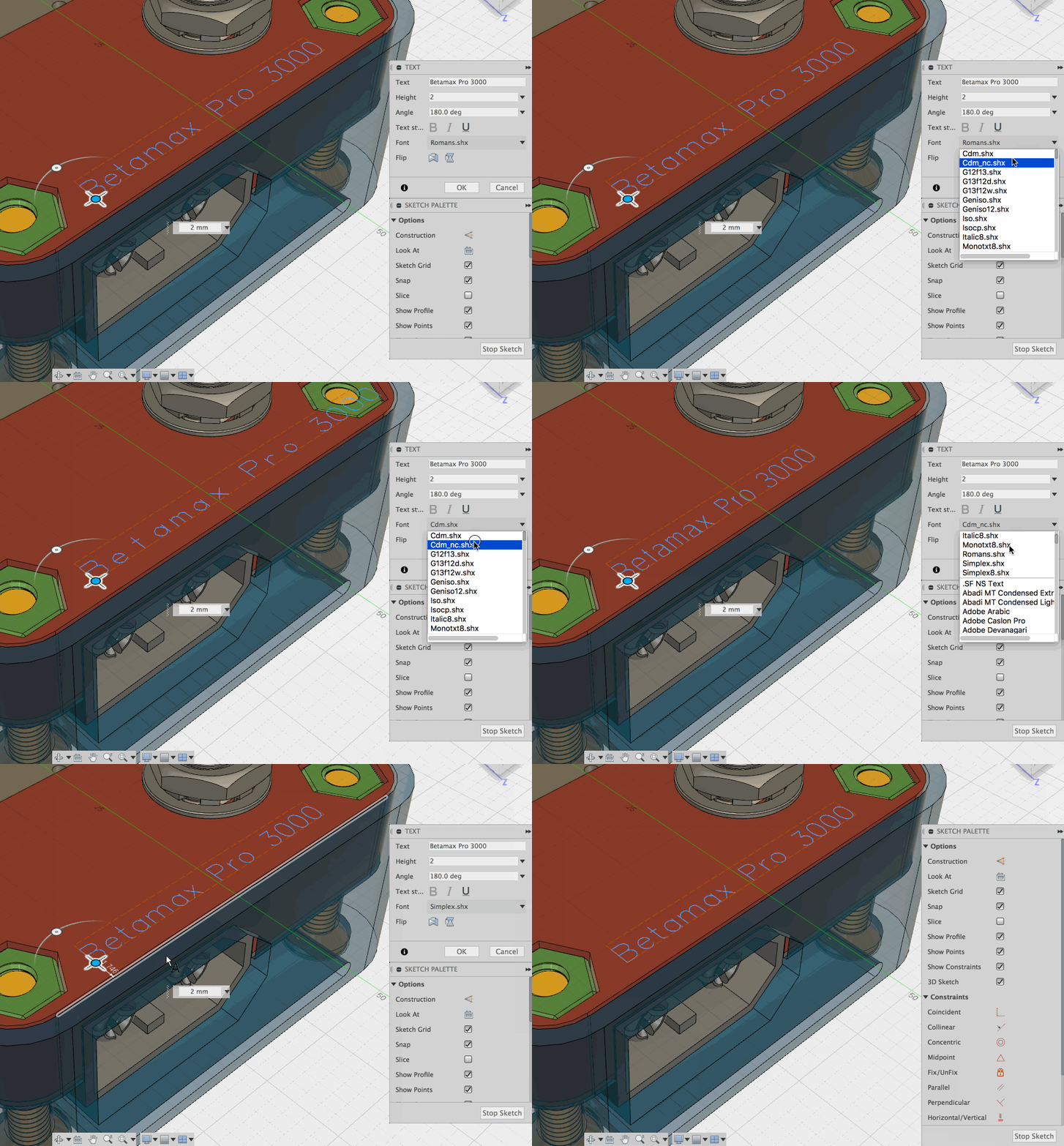
Another improvement that’s been highly requested (especially among you machinists) has arrived. Now when you invoke the Text command in the Sketch environment, you’ll see a number of .shx fonts in the Font drop-down menu. These are single line fonts, suitable for engraving operations in the CAM workspace. We’ve gotten feedback on some additional Sketch improvements like resizing behaviors and text on path, and we’re looking into those improvements for future updates.
Sketch Engine Improved
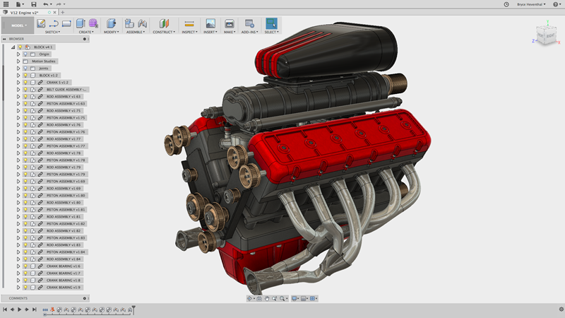
We continue to make progress here and have been making the sketch engine more robust and predictable. A great deal of effort has been put into fixing wonky issues with the solver and how it handles dragging of circular entities as well as feature reordering in the timeline. We’ve also made improvements to circular patterning and dimension constraints editing so that they no longer exhibit symptoms inaccurate results and crashing.
File Format Support
Fusion 360 can now read Inventor 2019, SolidWorks 2018 and, for the first time, Solid Edge up to ST9. Also for your reference, here is a list of supported formats.
Simulation
Plot 2D Probe and Include Tables in Results Report
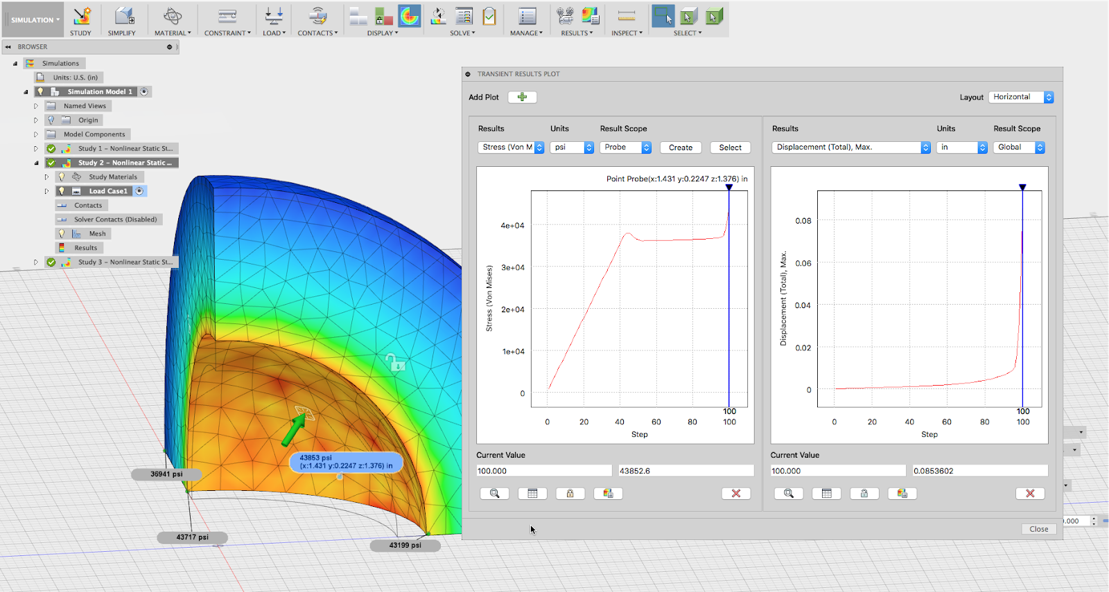
Previously when you made a result plot of simulation study, you were limited to plotting the global results. Now you’re able to include point probe data in your result plots, giving you another level of data that will help you make the right design decisions. Along with these 2D graphs, you’re now also able to include the associated tables in your reports for a more comprehensive view of what is going on in the study.
Send Model to Moldflow and CFD2019
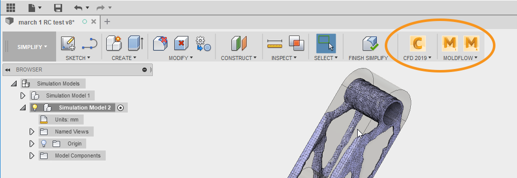
The Simplify workspace has been really popular for those of you taking advantage of the Simulation functionality. We want to open up all of this goodness for simplifying models for Simulation to those of you using Autodesk CFD and Autodesk Moldflow. Starting with the upcoming 2019 releases, if you have CFD or Moldflow installed and are using Fusion 360 (Ultimate), you’ll see CFD and Moldflow icons appear in the Simplify toolbar of the Simulation workspace. This will enable you to send your simplified Fusion 360 design into either one for further advanced testing.
Promote a Shape Opt’d Result to a Simulation Model
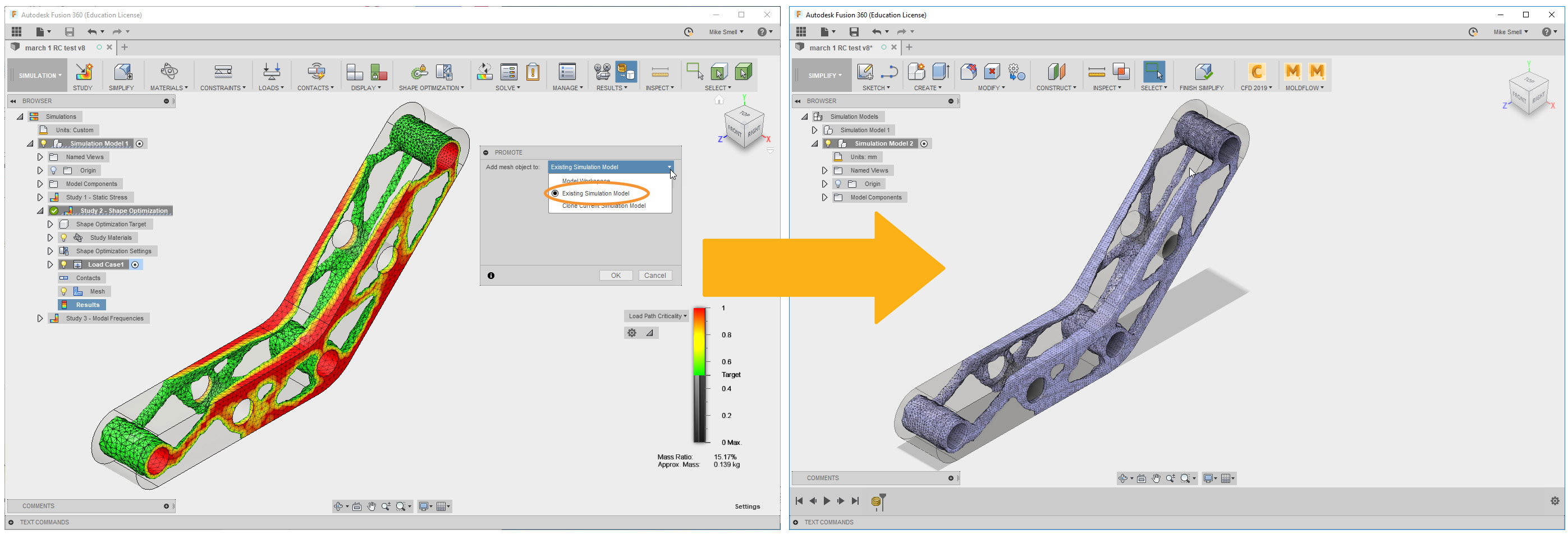
Shape Optimization in Fusion 360 is becoming more and more popular with users and we wanted to provide users more flexibility on how they use these results to redesign and validate their changes. In this release, users will now be able to promote their Shape Optimization results back into a Simulation Model where they can make design changes and run further studies to validate these changes without impacting their original design.
Nonlinear Static Stress Study Out of Preview

We’ve received a lot of feedback on how you’ve been using Nonlinear Static Stress (NLSS) studies, and have been working with you to improve the experience ever since the technology went live as a preview in Fusion 360. Now it is out of preview and available in Fusion 360 Ultimate as an advanced simulation study type.
Removing Components for Simplify is now 5X Faster
A good rule thumb to follow when you’re trying to solve run simulation study is to strip away any unneeded parts from your model that does not impact the simulation results. We’ve noticed that if you had a complex assembly, removing components from the design can take a very. Long. Time. We did some tuning to the compute engine and are happy to report that, based on our benchmarks, Fusion 360’s speed at simplifying a model for simulation has increased 5x. What used to take 2-3 seconds per part now fractions of a second.
2D Drawings
Object Snaps for Dimension Placement
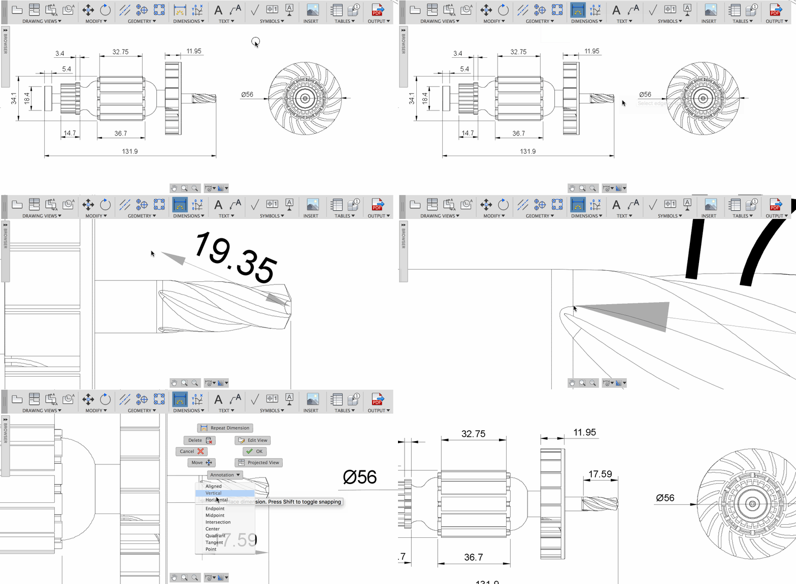
Now when you’re dimensioning your 2D drawing, you can override where you want your dimension lines to snap to by right-clicking and selecting one of many snap options available in the context menu, before you place your first snap location. Specifically, this will give you the midpoint and tangent snap options that you’ve been missing.
Insert an Image into Your Drawing
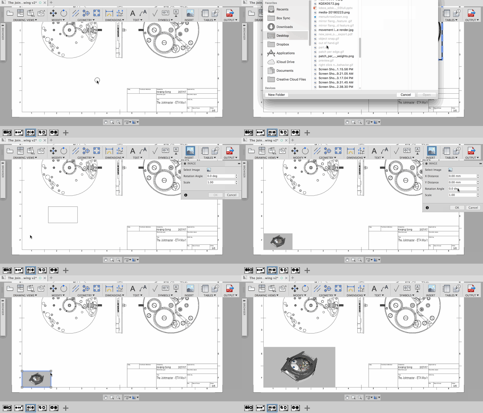
In addition to inserting your own logo into the title block, you can now insert images in the drawing (or drawing template) with a nifty Insert Image command. This should be useful for those you of looking to add reference images to your drawings, additional logos to your title blocks or even a watermark png.
Auto-Balloons From Table
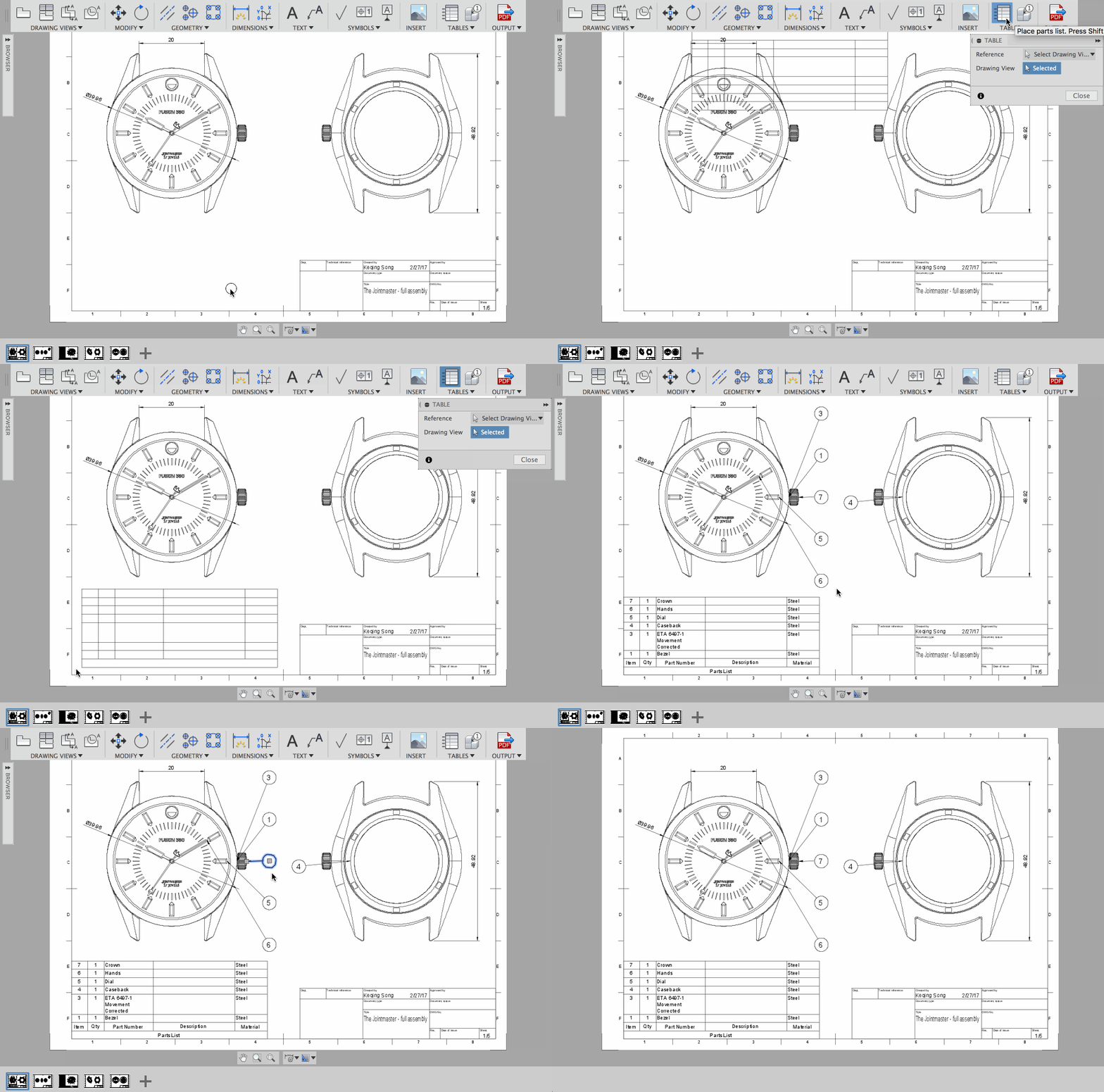
But wait, there’s more! Now when you create a table in your drawing or a template, balloons will automatically show up and correspond to the part listed in your table. It will also look at your views on your sheet and balloon across those views smartly to make sure each component called out can be clearly seen. You can always add more balloons to the design, but this will save you a lot of valuable time. Boom.
Centermark & Centerline Grip Enhancement
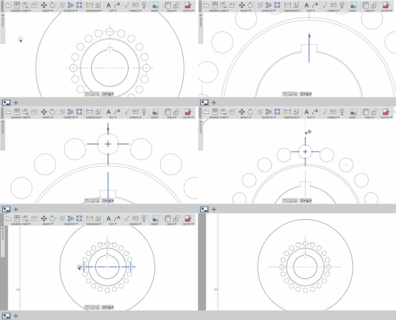
Leader lines for center marks and centerlines just got easier to manipulate. When have one of your center mark or centerline leaders selected, press the SHIFT key make the other leader lines mirror the one you’re editing. Press SHIFT again to disable to the mirroring. This way you don’t have change each leader line individually, because you have have more important things to do.
Tracking Along Non-Ortho Paths in Section Views
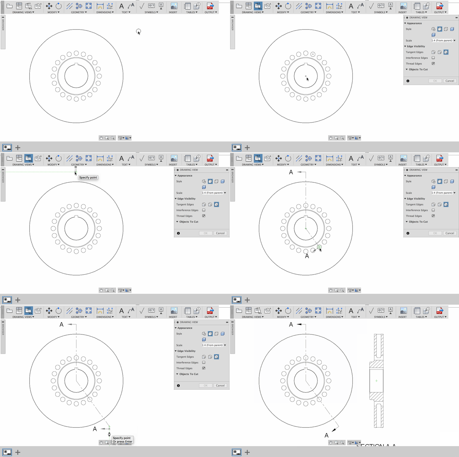
Previously there wasn’t a way to create this accurately. You had to ball-park where you were placing your Section View lines Now you can rely on where you snap and track along a non-ortho path to get your section view to look just right.
CAM
Both Ways Adaptive Clearing
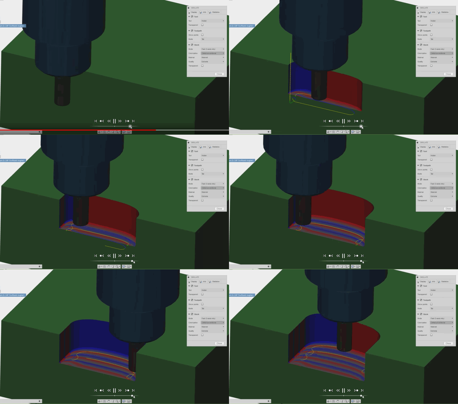
Adaptive Clearing was previously only able to generate roughing toolpaths in either climb passes only or conventional passes only. Now adaptive clearing can create 2D and 3D roughing toolpaths that dynamically choose between climb and conventional to decrease linking motion. You’ll be able control the optimal load and feed-rate for each direction individually when the cutting direction is set to both ways. Check out this short video to see it in action.
Toolpath Support for Sandvik PrimeTurning™
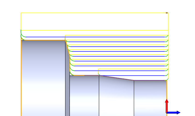
The Turning Profile operation in InventorHSM and HSMWorks can now create toolpaths that support the needs of Sandvik PrimeTurning™ inserts. These inserts are designed to be able to cut in many directions, but require special tool-path geometry to enter and exit the cut.
Pecking in Turning Profile
Each pass of a turning profile is a continuous contour that moves along the stock at a consistent speed (feed per revolution). The chip being formed by the cutting insert could potentially be one long strip of material unless that chip is broken up into smaller pieces. Insert geometry has improved over time to cause chips to break down into small, manageable pieces, but sometimes the material does not easily chip-form.
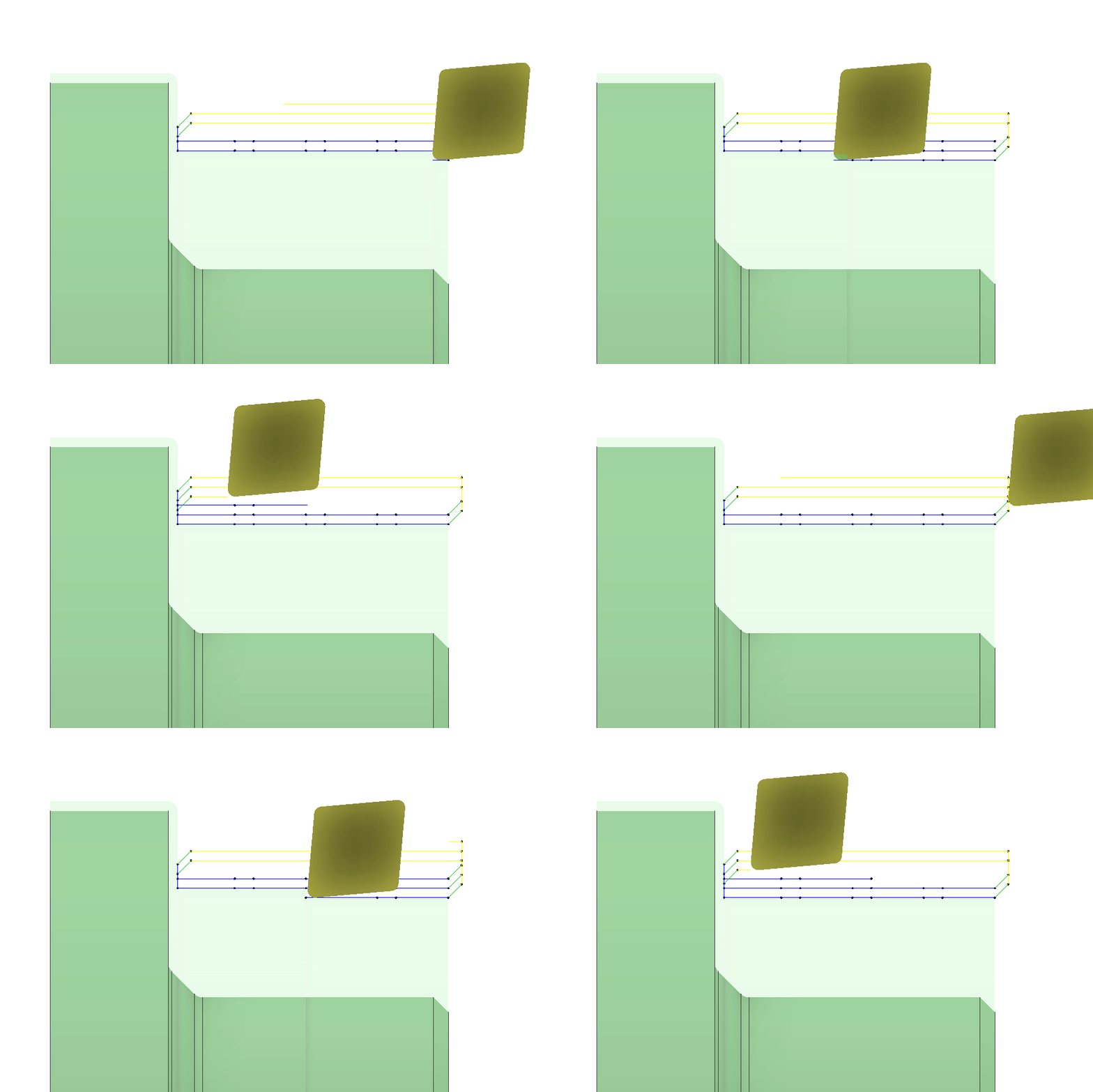
A new feature has been added to the Turning Profile and Turning Groove that will allow the tool to “peck” through the contour and force the chip to break at a specified distance. Users will also be able to control the back off distance of the tool on each peck.
Custom Turning Insert and Holder now out of beta
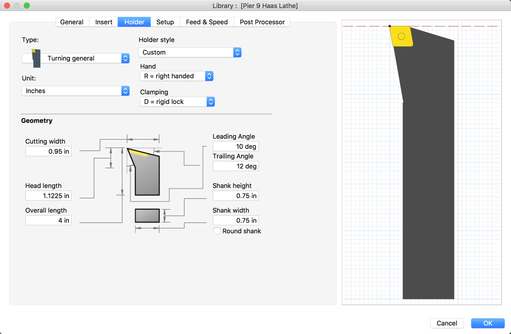
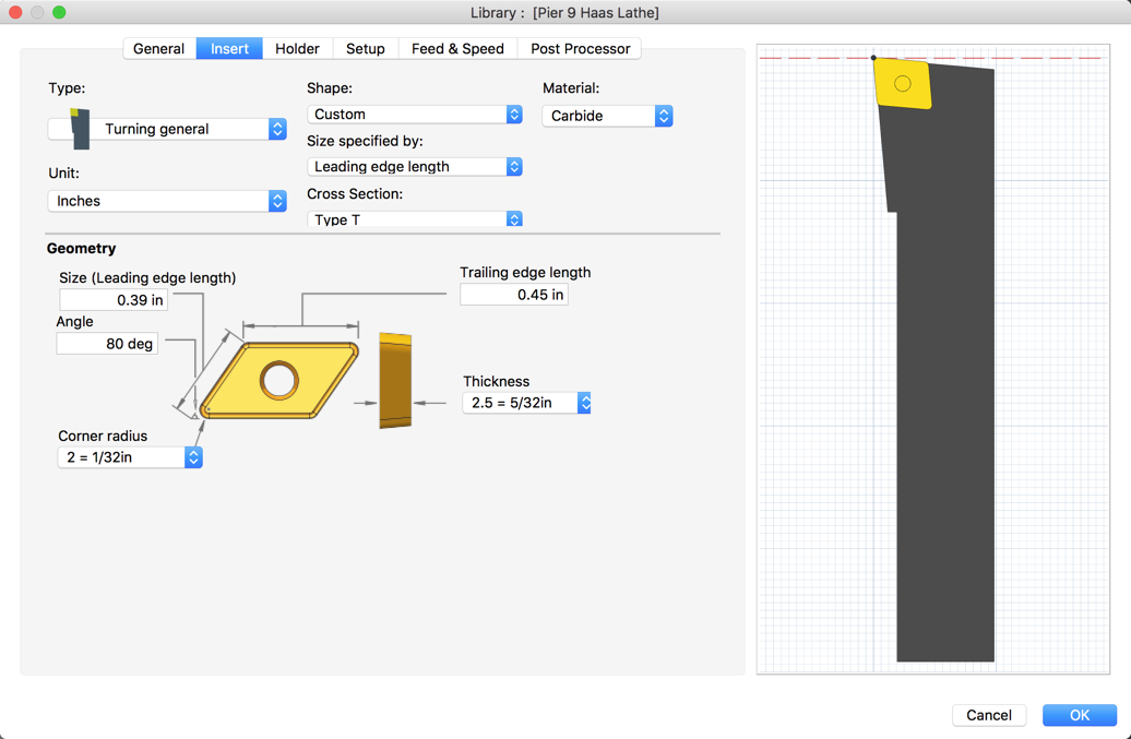
This update brought custom holder style and insert shape for Turning operations out of beta and made it available for everyone to use. Define the geometry you need to properly turn your part with maximum efficiency. As always, the preview image will update as you tweak your values, so you can see your changes in real time.
Tool Orientation Options for Probing
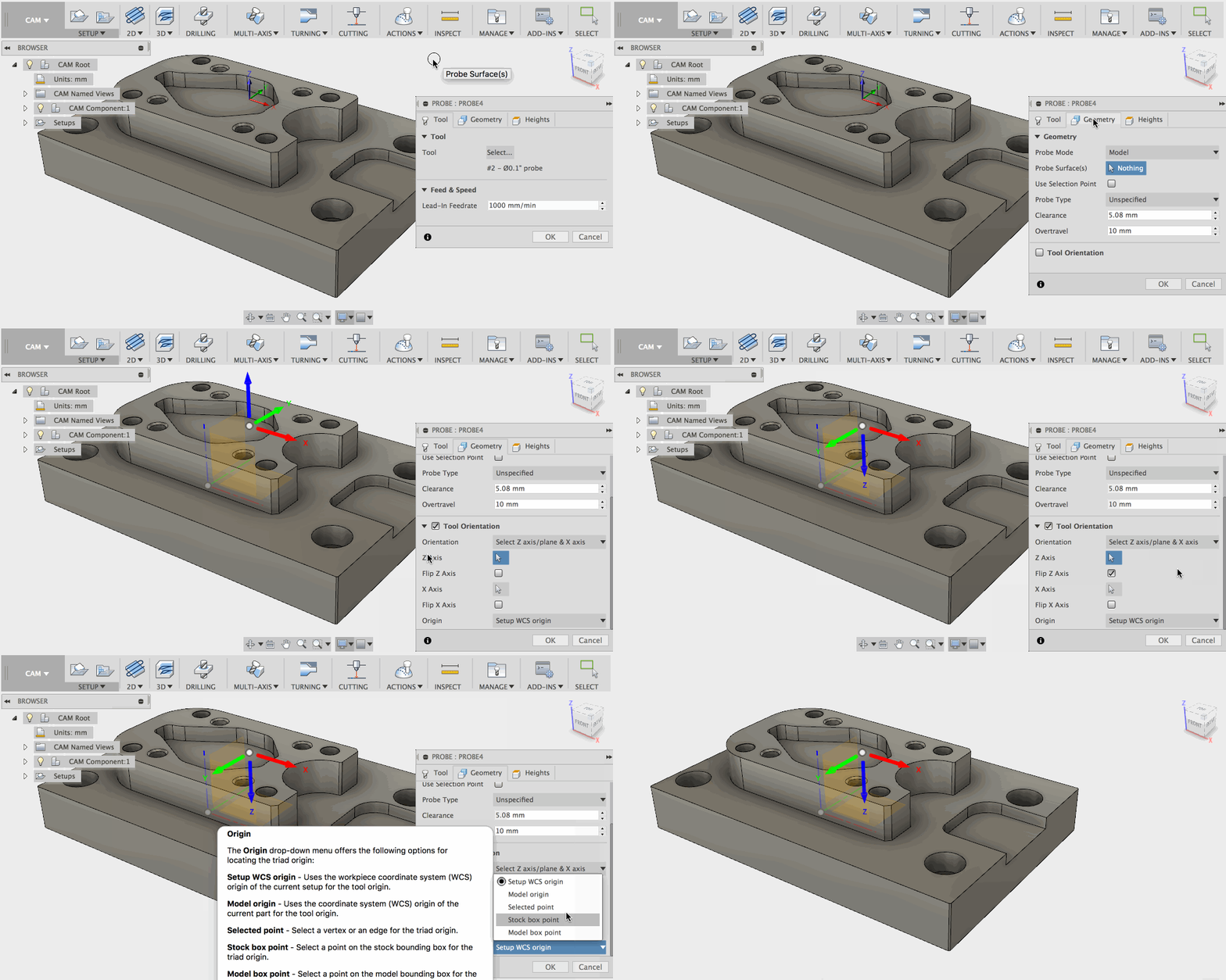
Within the Probe setup options, you’ll see Tool Orientation options in the Geometry tab. This will let you override the tool orientation defined in the setup, and use it specifically for probing. Instead of going back to the setup dialog, you can select which origins you like to use for your probe.
Tool Library Enhancements
Show, Hide, and Move Columns
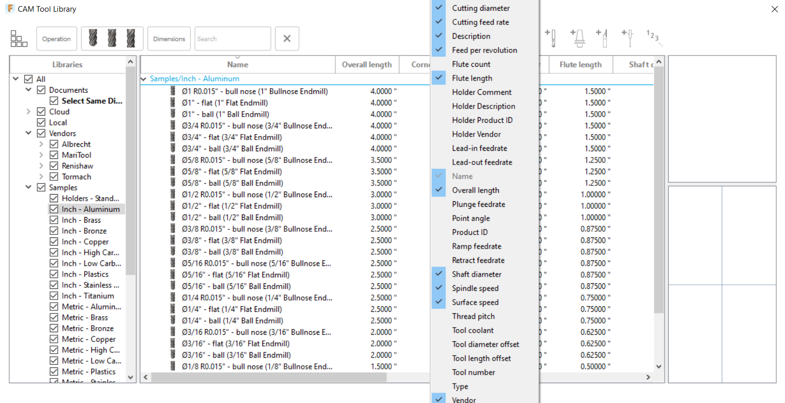
The tool library just got more flexible. You can now show, hide, and rearrange the columns to best fit their needs. Right click on any column header to select the columns that are shown. To rearrange the columns, simply drag and drop the header to the desired position.
Direct Copy & Paste into and out of Excel Sheets
Entering numbers one by one can be tedious, troublesome, and downright boring. You should be putting your time to better use, like filming chips fly. That’s why we updated the Tool library so you can highlight, copy, and paste from the tool library dialog directly into a spreadsheet, and vice versa. Now, let’s see some more chips fly.
Form Tool Preview Will Always Show Compensation Point
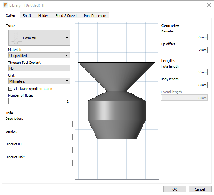
Being able to create custom form tools is rad, but there were times where a sufficiently large (positive or negative) value of ‘Tip offset’ caused the compensation point to disappear out of the visible area of the tool preview. We’ve updated how we scale the preview so that the compensation point is always visible.
Drilling Enhancements
Hole Counter
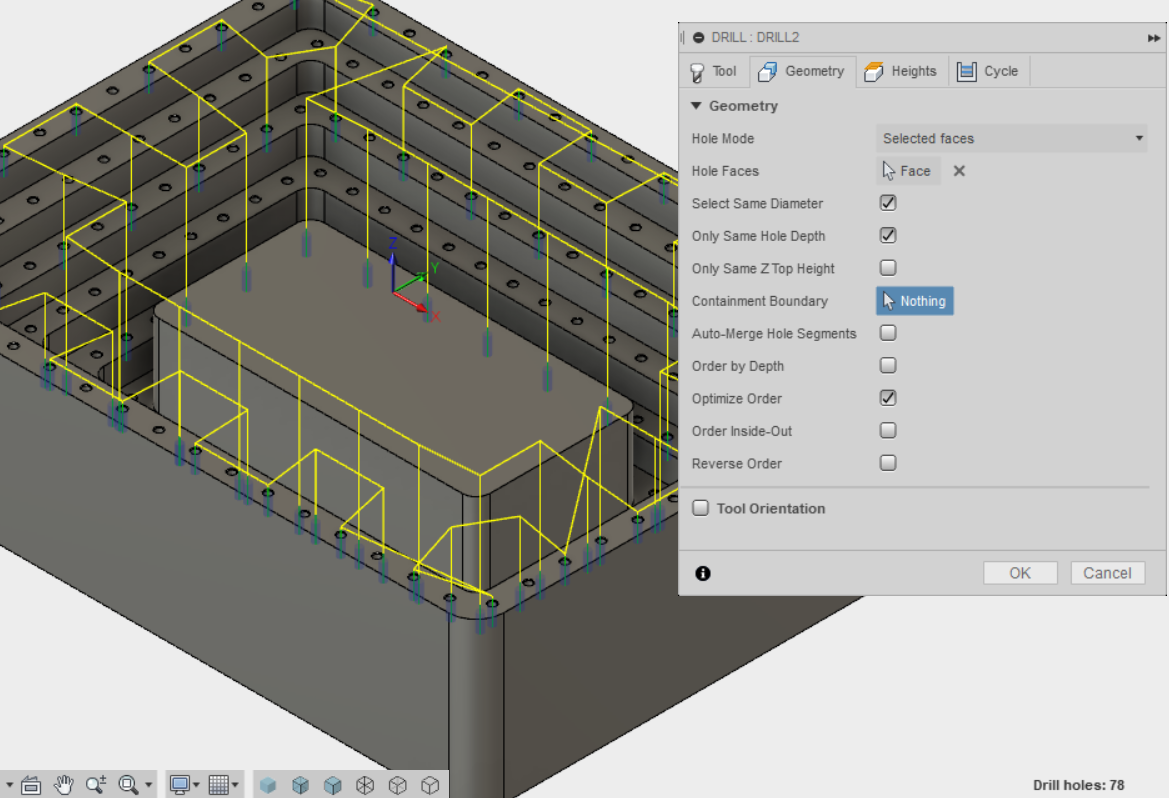
The drilling operation now shows the number of holes that have been selected. This is particularly useful when using “select same diameter” to automatically detect similar holes and verify that the operation has found the proper number of holes.
“Select Same Diameter” Driven by Sketch
Previously if you had a lot of holes to drill (like 1000+ holes), it can easily escalate into a very daunting task. Checking the “Select Same Diameter” option didn’t grab holes based on the sketch, and the modeling side doesn’t really scale to handle that many holes either. Now, the “Select Same Diameter” option can be driven by the sketch, making it easier on your to select what you need and offloading the task to Fusion 360 to do the heavy lifting.
Containment Boundary filter
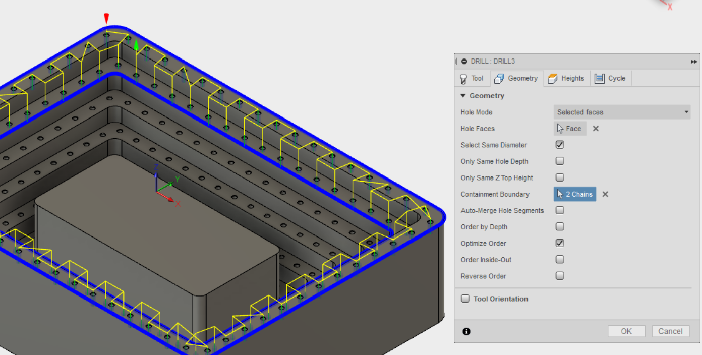
This does exactly what you think it does: it lets you contain a set of holes to drill by setting out a boundary around them. Any Edge or sketch geometry can be used as boundary definition, and once set, the toolpath will be inside the contained area. You can use Containment Boundary in conjunction with Select Same Diameter and Diameter Range.
Reverse Order
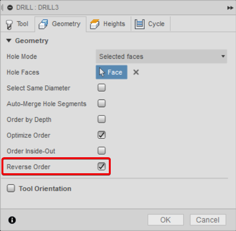
The order that holes are cut in can be optimized in the drilling operation, but now you have the option to reverse the order. An example where this would be useful is when performing two operations on one set of holes, like drilling then tapping. The tapping operation can now be set to start on the last hole cut by the drilling operation, eliminating the initial positioning move that was previously required.
Machine Definitions
Also referred to as Machine Configurations, we’ve been making good progress and implemented the first phase of it in Fusion 360. A machine config essentially contains information around the axes limits, maximum spindle speed, feed rate limits, and axis configurations that talks directly to post processors. This will help streamline the process of creating Multi-Axes post processors. It’ll also alert you to potential issues in your strategies while making tool path decisions.

To use it, make sure you have Machine Configurations checked in the preview section of your preferences.
Updated Post Processor and CAM Kernel
Fresh from the top secret engineering laboratories come the latest HSM post processor and kernel, now inside Fusion 360. We grab the latest version and pack it into each product update, so you can benefit from its performance and stability, as well as a slew of bug fixes.
Fixes and Improvements
We’re jazzed to be getting this update out to you guys, and always love seeing how you are taking advantage of everything Fusion 360 has to offer. In addition all the goodies highlighted here, we’ve also made big strides on fixing annoying issues and improving performance of the software. Here’s a list of our fixes and improvements. Even if you haven’t noticed many of these, it’s still worth a quick gander.
P.S. Hello, Portland!
Autodesk has offices all over the world, and yesterday, Autodeskers in Oregon, USA (including yours truly) started their first day of work in the new Portland office. This move from Lake Oswego, OR to downtown Portland was a dream years in the making, and yesterday it finally became a reality! After searching for quite some time, we found an old storage building that was being renovated. Working with city officials and local developers, we turned the space into one of the best tech offices ever, as well as keeping with it’s historical and original aesthetic.

Also, it isn’t Portland without a bit of Portland flare. Fusion 360 was born out of these parts, and it’s future just got a whole lot brighter. With this new space, we plan on sharing it with startups, customers, and users like you, so that we can help each other on developing better products. We’re super excited about the opportunities that lie ahead, and want to share our excitement with you. if you’re ever in the Portland area, drop us a line; we’ll show you around!
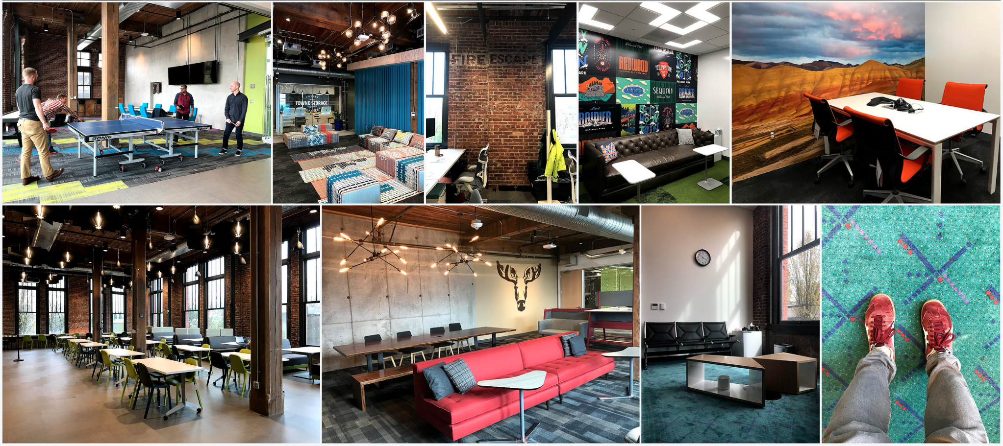
Keqing, Fusion 360 Team in Portland, Oregon and around the world
May 21, 2018 Product Update – What’s New
Latest fix in 2.0.4126:
We pushed a small update last night that included a number of fixes in CAM, Drawings, and how you select license types.
Fixed in CAM
- Unable to generate contact curves for given drive curves.
- Bottom height reference was lost when you were in the edit operation.
- Hole selection in Fusion CAM was wonky and didn’t work properly.
- There was an issue where you couldn’t generate the correct Rest Machining Turning toolpath.
- Crash issue when trying to create Form Mill tool.
- Delete command was not work in the tool library for some reason.
- The kernel issue related to Mac environments.
- Mac-only: Post Processing Property Values not applied.
- Parameter tooltips were missing.
- Rest machining operation wasn’t validating correctly when reordering operations in the browser.
- Stock Simulation was showing part gouge even though there wasn’t one.
- Tool-type filters were not maintained when switching between libraries.
- Turning Rest Machining created the wrong toolpath and gouges the part.
- Turning roughing ignored model.
Fixed in 2D Drawings
- A number of crash issues in 2D Drawings since the April update. We’ve patched up a number of areas here so things should be a lot more stable now.
Offline issue fixed
tfarllc reported an issue where he wasn’t able to access any Fusion 360 Ultimate features if we went offline. This was pretty embarrassing. Apologize for the mix-up. This is now fixed.
Latest fix in 2.0.4116:
We fixed a high priority crash issue in modeling, and another nasty one in Sculpt.
Apparently you were also crashing when you tried to share a rendering to the Fusion 360 gallery. It should now go through smoothly.
Latest fix in 2.0.4114:
We fixed an issue where cloud renderings weren’t able to be downloaded. Our bad, something was clogging up the pipes. Now it’s working smoothly again.