2.0.2995
Here are a couple of fixes dropping in hot.
We fixed a bug that could potential cause memory corruption on startup, which is never a pleasant thing to experience.
We also squashed a sheetmetal bug that crashed Fusion 360 when you tried to create a line/arc on the face of a sheetmetal flange. Gross (but now it’s gone).
April 19, 2017 Update – What’s New
2.0.2989
Data Management
New! Job and service status
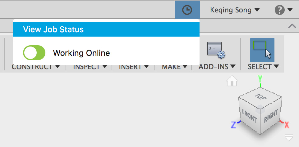
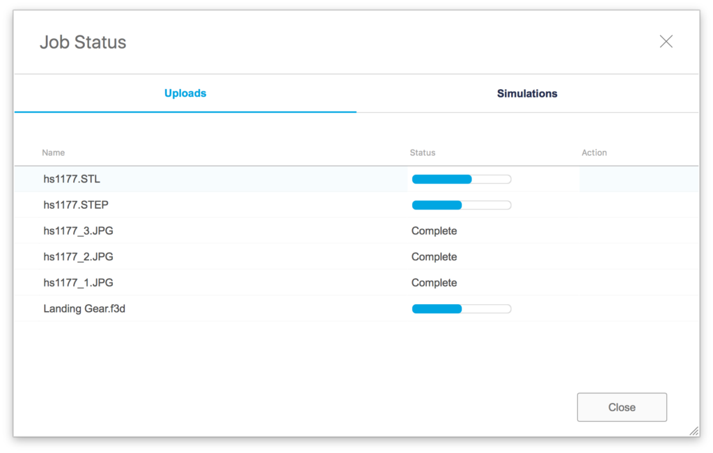
We’re introducing a new icon next to your name in the top right corner. Click it and hover over the View Job Status area to see data uploads and simulation cloud solves happening at any given moment. This makes it easier to monitor what’s been uploaded and the status.
New! Better Online/Offline Switch
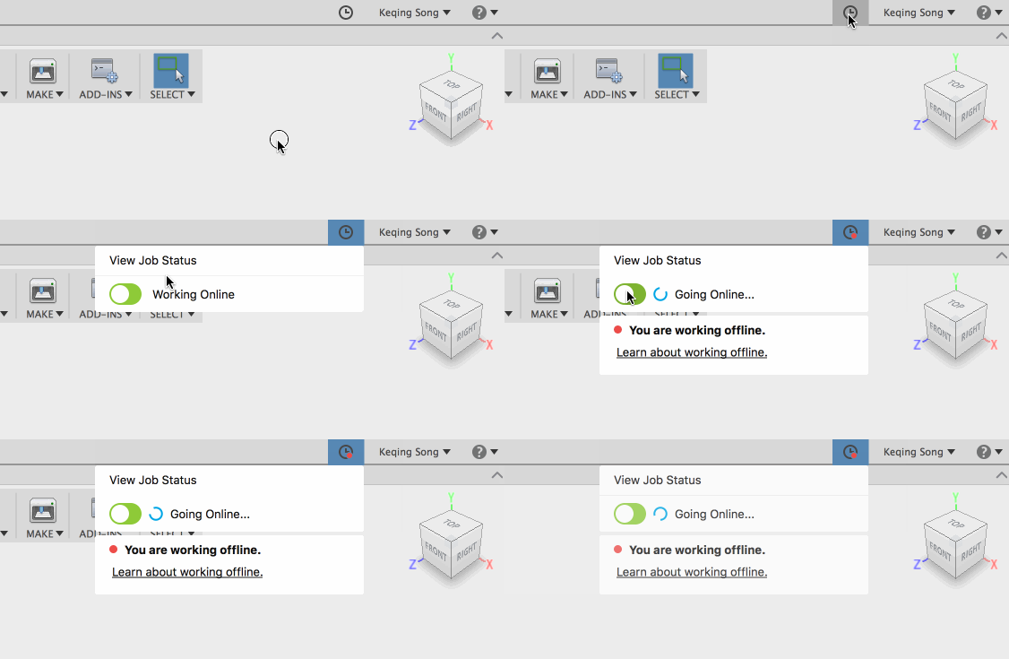
Right below the View Job Status section is a better Online/Offline toggle switch. Toggle it and you’ll go into offline mode. Toggle it again and Fusion 360 will reconnect and be back online. Simple, the way it should be. Offline mode remains unchanged.
New! Service Notifications
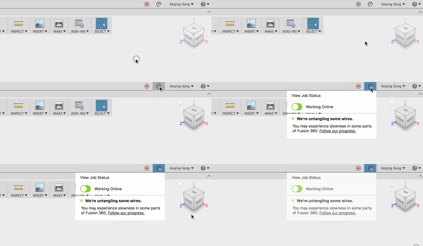
Oh yeah, there’s more. In case there’s an unexpected service interruption, a yellow or red dot will appear on the clock icon. A yellow dot indicates unexpected latency or slowness in some area of Fusion 360. A red dot will automatically put your Fusion 360 into offline mode. Both yellow and red dots will go away when the issue has been resolved, and your Fusion 360 should automatically reconnect.
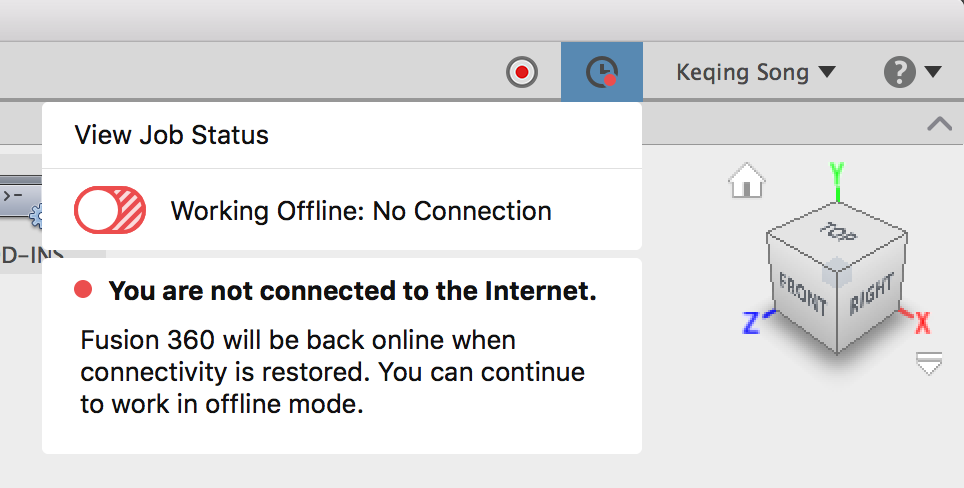
Think of the online/offline toggle as a light switch in your house. If you lose power, the switch remains on the “on” position. If power comes back, your lights come on again.
New! Related 2D Drawings now accessible in design details

Now when you get into the design details of a specific design, you’ll not only see the versions, uses, and what it’s used in, you’ll also see the related 2D Drawings associated with the design. This will make it easier for you stay organized and find the right drawing for the right design in a jiffy.
Modeling
New! Interrupt/stop a compute or timeline playback

A couple of updates back we moved the play button to the middle. Now when you accidentally play the timeline, you can stop it from playing. And yeah, we know the feeling of uncertainty not knowing whether a compute is happening correctly or if it’s hanging the software. That’s why you can now also press the ESC key to stop a Compute All, a parametric feature edit, a Finish Form, or Finish Base Feature that’s taking forever to compute.
Improved! Move command only captures final position when moving components
We noticed that every time you moved a component with the Move command, it would give you the option to “capture position” on every move instance. No no no. What really should happen is for the command to capture the final position, not all the incremental ones in-between. Now it’s working correctly.
Improved! New group folder now appears at the top
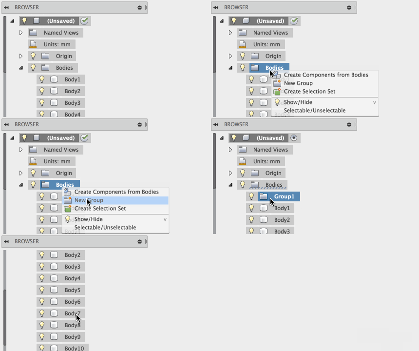 We mentioned in a previous update that when you were able to create new group folders within the Bodies folder to keep things tidy, yet when you did this, the new group folder went all the way to the bottom, which was annoying. Now when you create a new group folder, it appears at the very top.
Improved! SHIFT+select now only includes visible features in an active component
There as was weird behavior where you SHIFT + select a series of timeline features in an active component, other features in other components that were committed in that timeframe also got included. Now SHIFT+select only includes visible features of that specific active component, as it should.
Notable Fixes:
- Editing a thread and then cancelling out of the command no longer loses the thread.
- SolidWorks 2017 now works with Fusion 360.
- You can now stay in the Align tool and align multiple components without needing to re-invoke it over and over.
- We fixed some code so that Midplane behaves better and truly remains in the middle.
Sketching
Delivering on what we’ve talked about in our recent roadmap update, here are some words from Jake Fowler, our UX designer extraordinaire for sketch related projects:
 “Our updates for sketching this time around is all about 3D (well, aside from a good batch of 2D solver fixes as well :). We’ve introduced 3D coincident constraints (which now work consistently across 2D and 3D), and we’ve made a number of simple but effective productivity enhancements for 3D spline workflows, which should make splines much more intuitive for defining 3D forms.”
New! 3D coincident constraints
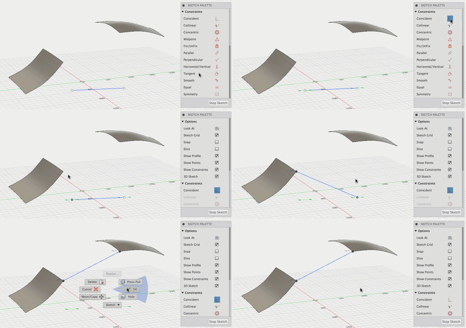
Previously you weren’t able to constrain a sketch entity to a point of a piece of 3D geometry in 3D space. Now constraints will work between sketch entities and points/vertices in 3D as they do in 2D.
Improved! Create tangent/smooth constraints directly with model edges
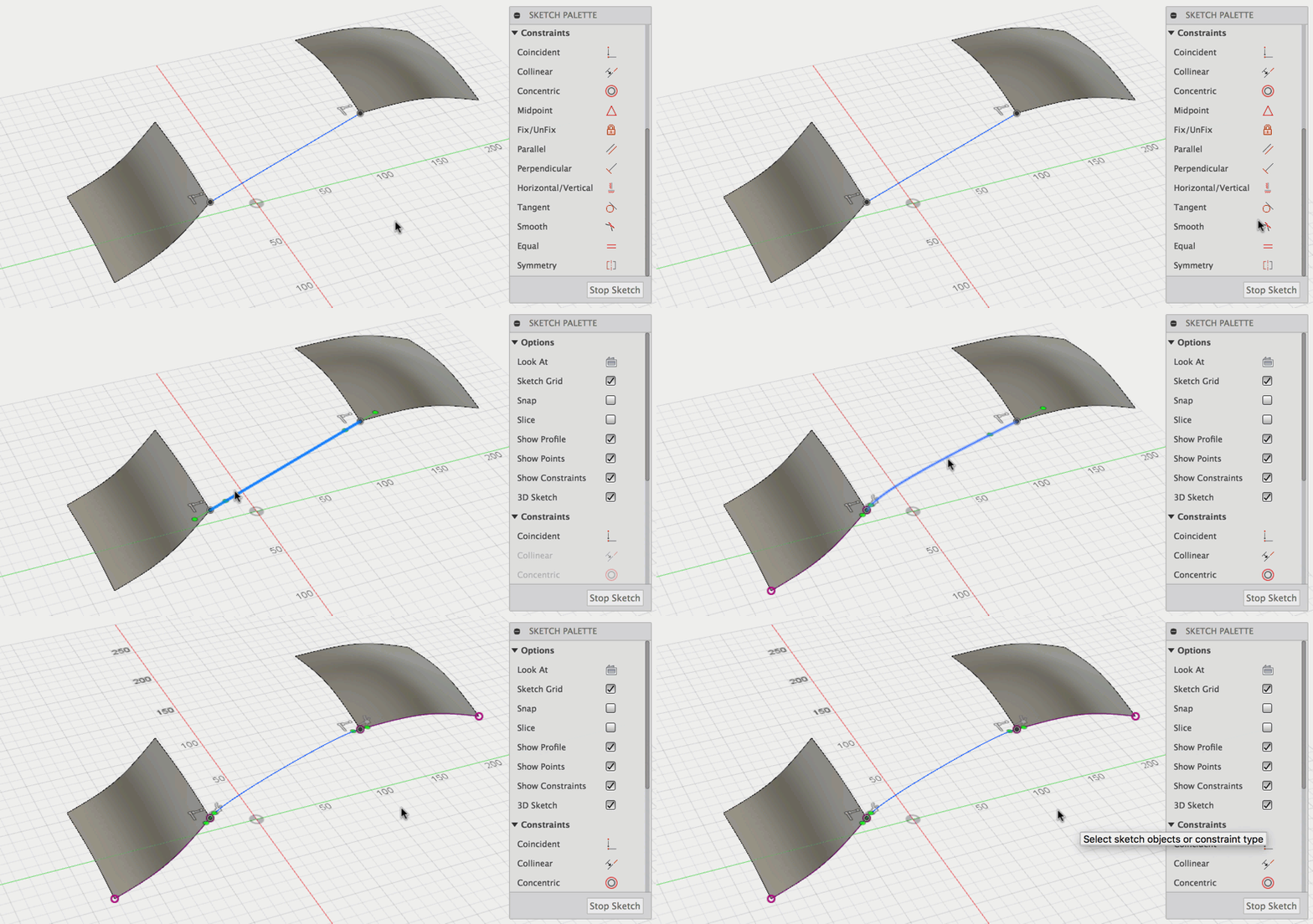
We made tangent and smooth constraints work better, so that you no longer have to manually include 3D geometry in the sketch. You should just be able to pick the edges you want your sketch entity to be constrained to and poof! It’ll just work.
Improved! 3D spline handle control
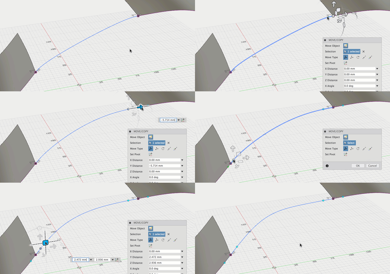
Using the Move/Copy command manipulators to move spline handles used to be very wonky and if you didn’t know the secret handshake, you were not gonna be having a good time. Now Spline handles are shown/hidden in Move by selecting spline points and all of them can be edited directly in the Move tool – no need to activate first.
Improved! Moving and dragging spline point
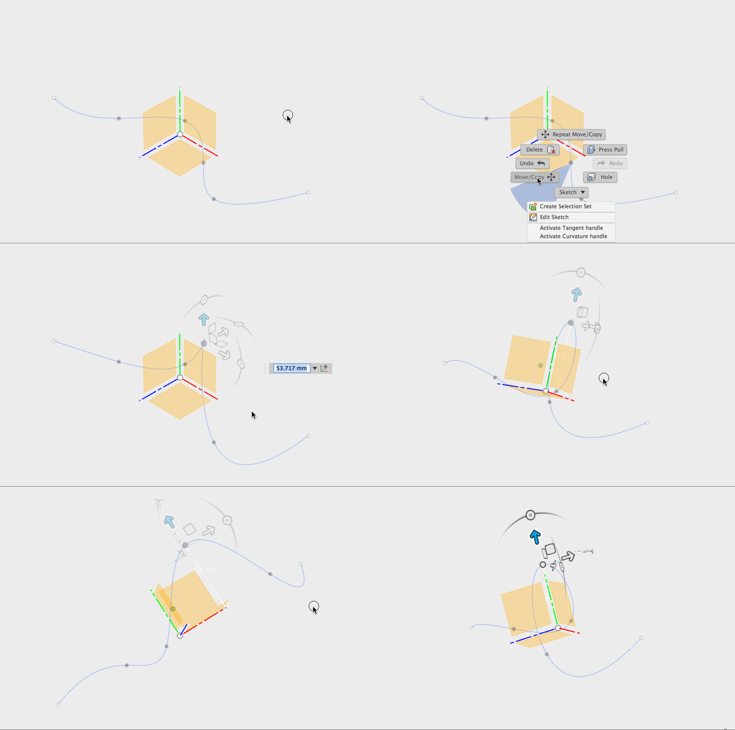
Now when you use the Move/Copy command and drag a spline point by using the manipulators, the point will leave its origin plane as expected, and not end up something way off into the distance on it’s own plane.
Solver and other fixes:
- We’ve improved solver performance so that sketch pattern solves happen faster and dragging behavior is better.
- SVG import is now less finicky with certain types of SVGs, and we’ve noticed less crashes as well.
- Points that have been previously fixed can no longer be double fixed.
- You no longer have to press Tab twice to lock dimension values and jump to the next one.
- Sketch lines drawn to a Spline midpoint now created a coincident constraint.
Sheet Metal Preview (limited access)
We’re making progress here, and are thrilled to see how many of you are trying it out, telling us what you think, and creating awesome designs with it. Thanks to your feedback, here are some new improvements made to the preview.
Improved! Sheetmetal now right below Patch in workspace switcher

The way our workspace switcher is organized is based on a typical idea-to-part workflow. This just makes sense since it’s part of a modeling workflow. Just to be clear, Sheetmetal functionality is still in a limited preview phase, and it is not available for everyone to try. If you want to get in on the preview, check out our preview forum to see how to to sign up.
New! Join contour flanges to a sketch
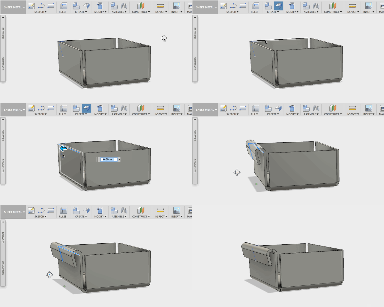
Those of you trying sheet metal functionality will have to check this out – you can now join your flanges and make them follow a sketch contour. Create a sketch, select the edges you want your flanges to start, then select the sketch, and voila.
Technically, you can start creating hems with this functionality. All you have to do is sketch the shape out and Fusion 360 will take care of the rest. Editing the sketch will update the flange in real-time, making it easy to fine tune your design.
New! Miter option now available in Flange tool

Now when you create edge flanges, you can toggle the Miter option so that you flanges are nicely mitered. Or not. Your choice. What’s important is that it’s there.
New! Control miter gaps

With the miter option, you’ll want to control the rip/seam gap your miter flanges. While editing your rules, you can change the value of the Miter/rip/seam gap and once saved, your sheet metal part will instantly update.
Improved! UI for editing and adding rules
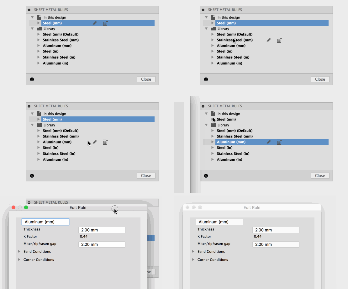
Instead of right-clicking on a material in the Sheet Metal Rules library to edit the rules, we’ve added an edit and add icon next to each one so that they appear when you hover over the material.
New! Reassign rules for components

If you have multiple sheet metal components with with different rules and you realize that you need to change the rule of one component to another rule, you can now do it by clicking on the Change Rule button, select the rule you want, and your sheet metal part will update with the new rule. Piece of cake.
New! Copy rules to library
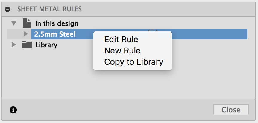
Made a custom rule and want to save it to your library? Right-click. Select Copy to Library. Done. Profit.
New! Bend and Corner overrides

Not all flanges are created equal, and some require special treatment. While you’re creating your flange(s), you can now override bend and corner rules for that particular component. Overrides include Bend, Bend Relief, 2 Bend Corner and 3 Bend Corner.
2D Drawings
New! Create detail views and projected views of a section view
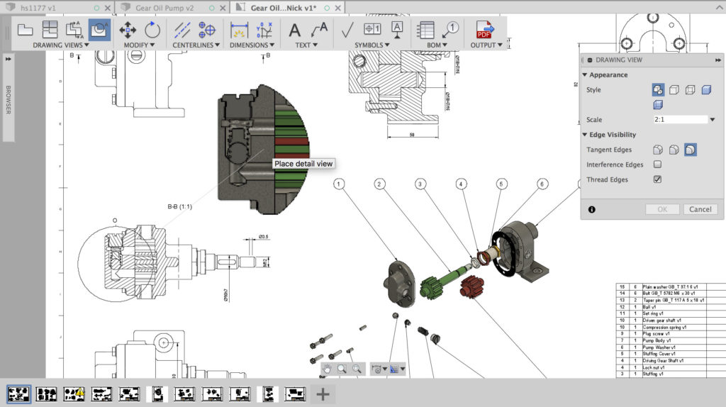
Yo dawg, I heard you like to chain your views, so we dropped some new code into your Fusion 360 so you can detail a section view while you create a projected view from another section view or even create a section view of a section view. Aww yeah.
New! Section View – Objects to Cut Control
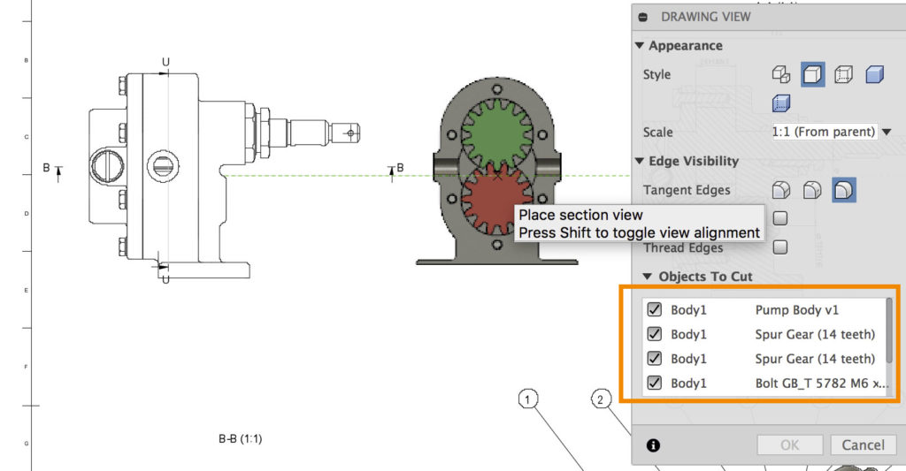
Previously when you created a section view of an assembly, it’d be a section of the whole thing. Now you have the ability to select which components / bodies should participate in the section view, and which ones should be left out.
New! Text alignment and numbering
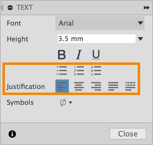
Now when you put a text box in your drawing, you’ll be able to bullet, number and letter them in order, as well as give the text a certain alignment type (Justification).
Also as a quick tip, you don’t have to re-type and format everything if your drawings require the same block of text on multiple sheets (like for a confidentiality or general tolerance note). With the text box open, highlight what you want copied and Cmd+C / Ctrl+C, then Cmd+V / Ctrl+V inside another text box on the same or different sheet to copy the contents over.
Improved! Single PDF output for with multiple sheets
In this last update we brought you multi-sheets, but the PDF output ended up giving you 1 PDF file for every sheet you had. Now when you export your drawing as a PDF, you’ll get a nicely packaged single PDF with each sheet as a page in that PDF. Woohoo!
Rendering & Graphics
New! Section analysis – custom colors

The Section Analysis tool now has an option for you to give whatever you’re sectioning a custom color. By default, each component being sectioned will have it’s own session-assigned component color. Switch the Section color to Custom, pick a color, and the section analysis will update to that color.
Improved! Decals now visible in 3D web viewer
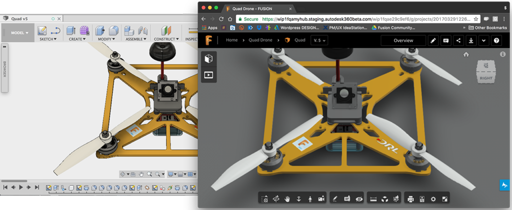
Gone are the days when you would share with someone a public share link of your design and the decals on your design were missing in the 3D web viewer. Now your sweet logos will be displayed as expected.
Improved! Local rendering and cloud rendering now using unified rendering engine
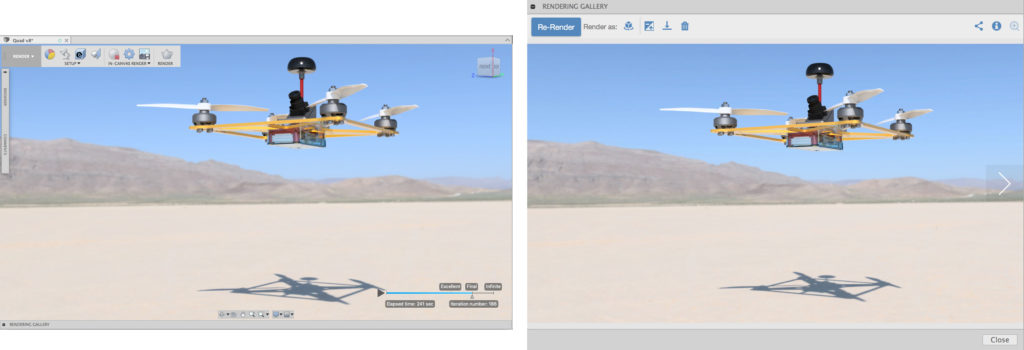
Regardless of which rendering path you take (local or cloud), your renderings will now look the same. This is because we finally unified our rendering engine so that your results are consistent across the board. The one of the left was locally rendered and the one of the right was rendered via the cloud. Other than the UI around rendering, you really can’t tell the difference between the two.
Simulation
Improved! Adaptive Mesh refinement UI
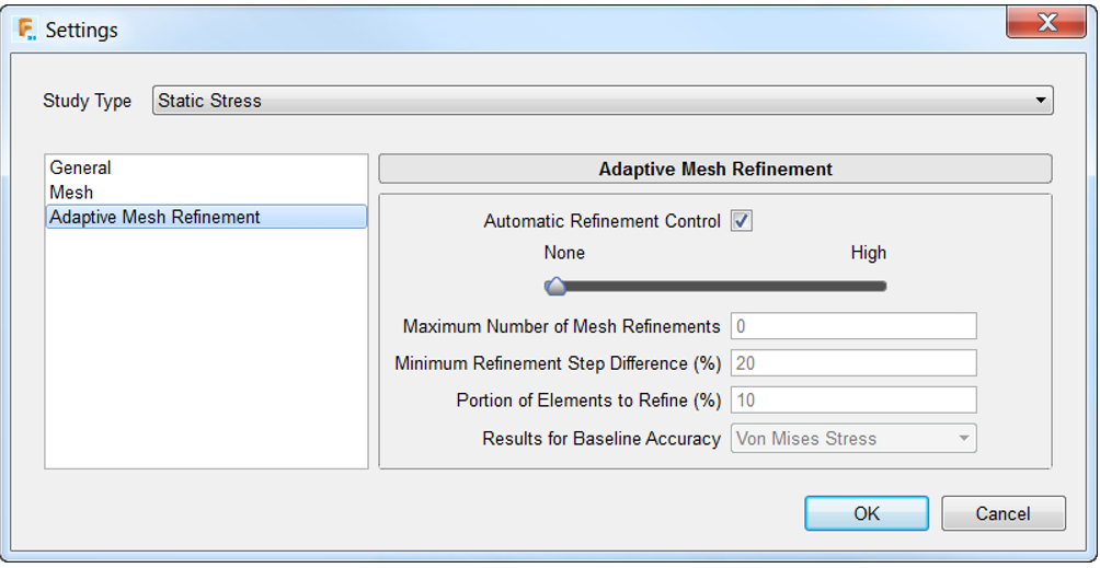
This used to be the old dialog for Adaptive Mesh refinement. It had a weird user experience. Sliding the slider from None to High lacked any sense of incremental adjustments, and checking/unchecking the Automatic Refinement Control felt clunky.

We cleaned up the dialog with better slider increments and ditched the useless check box. Much better.
HSM CAM
New! 3D Morph Strategy
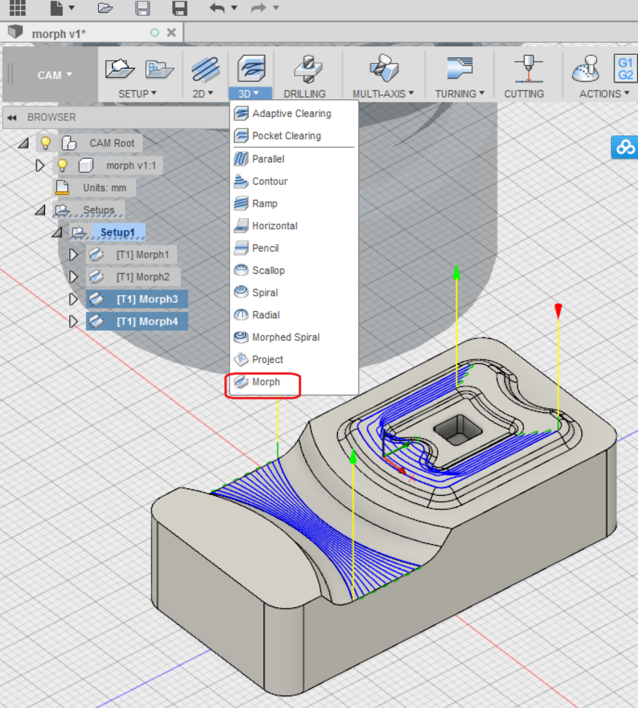
It’s time to put your Mighty Morphin’ Power Ranger costume on, because Morphing toolpath strategies are now available under the 3D toolpath drop down menu. Morph is a finishing strategy that is really good for shallow areas between two curved contours that require a consistent cutting direction. We’ve been testing this for awhile, and now it’s turned on for everyone.
New! Create toolpaths directly on mesh bodies preview
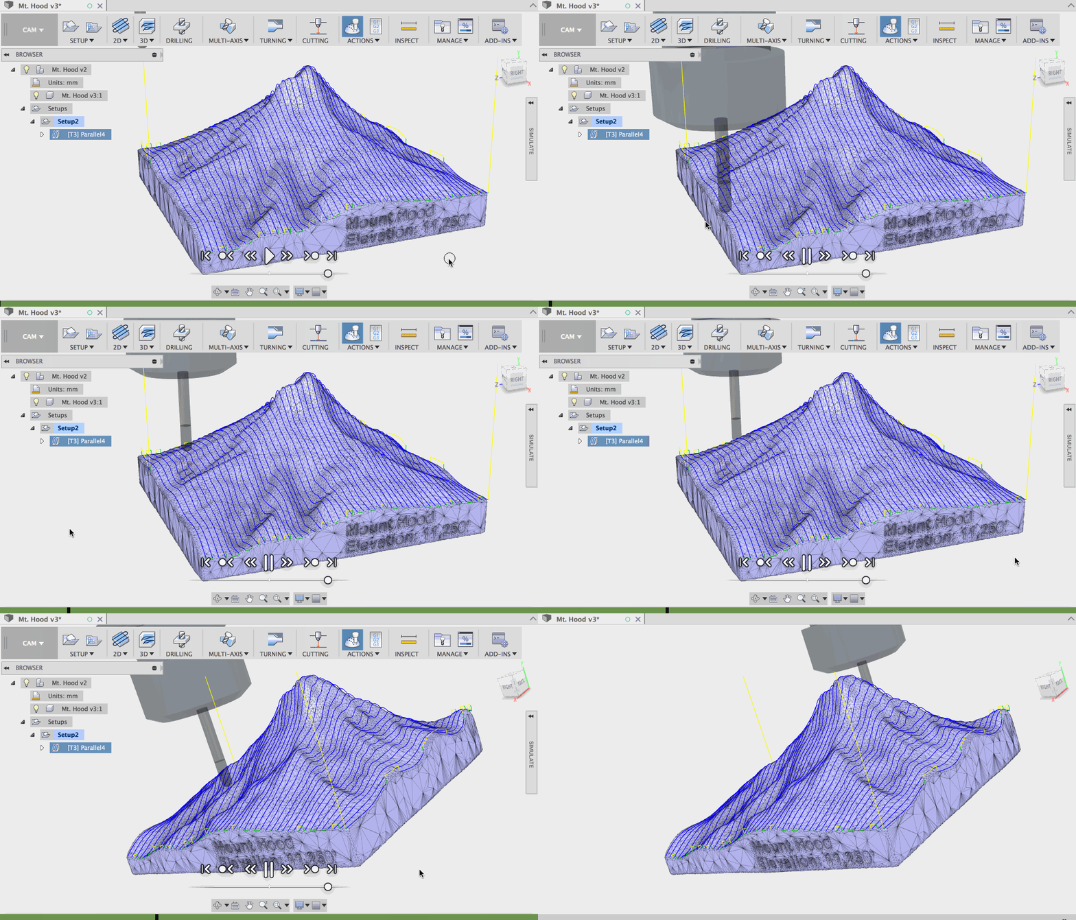
Yes! You can now bring STLs and OBJs into the Mesh workspace preview and then create CAM toolpaths directly on top of them. Here’s how to do it.
Start by going to Create > Create Mesh. This will take you to the Mesh workspace. If you don’t see this option, make sure you have it check in the preview section of your preferences.
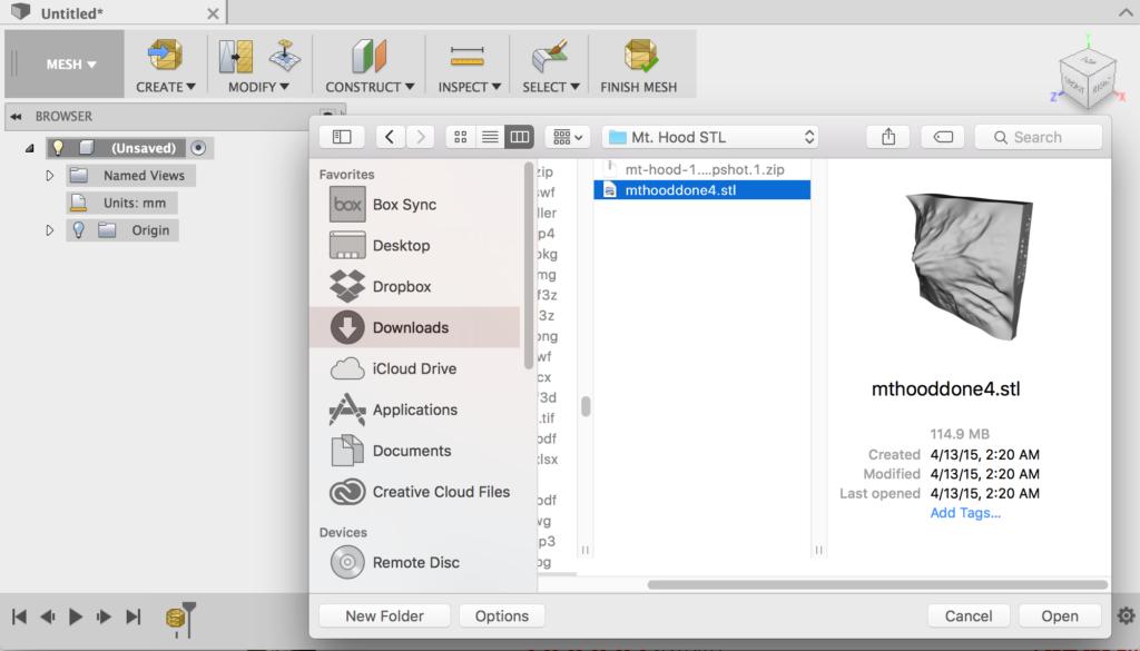
Next, click on Insert Mesh and find the design you want to work with.
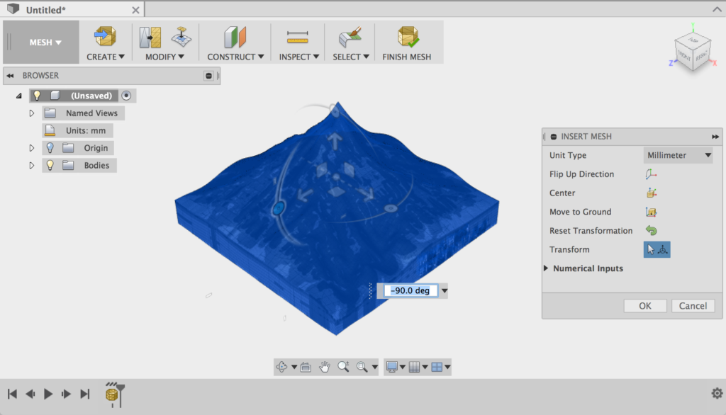
When it comes in, you’re gonna want to rotate, center, and ground it appropriately.
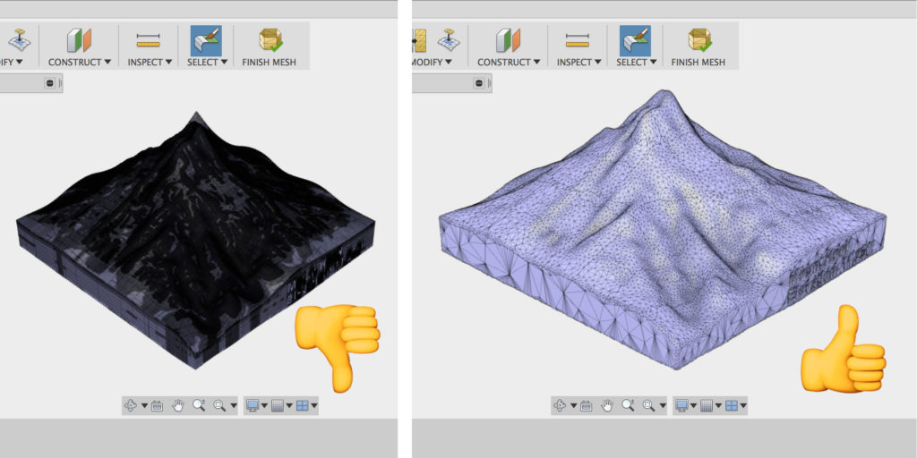
Chances are, the design you just brought in is way too dense. You’ll want to re-mesh and reduce it so that it’s more usable. As a reference, here’s a before and after comparison of the design – one of the left is way too dense, and the one on the right is good to go.
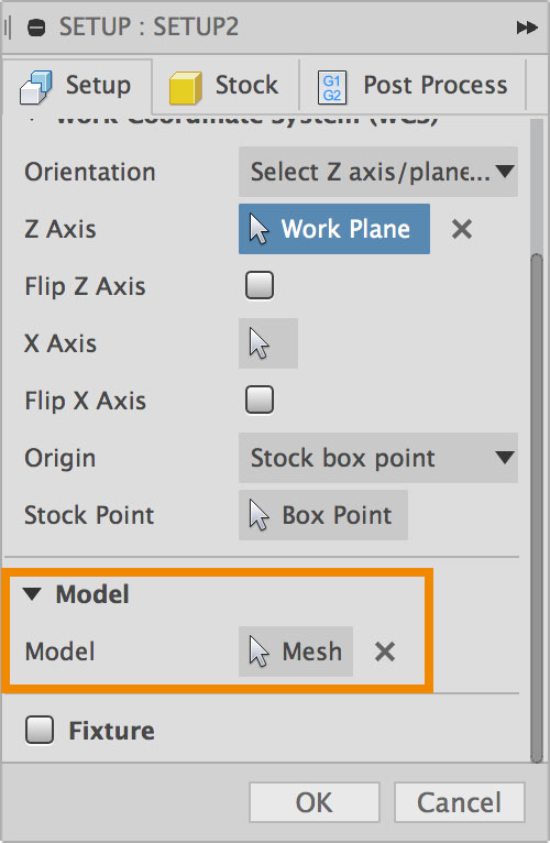
Once you have your mesh body cleaned up, hop over to the CAM workspace to start creating your toolpath strategies. Make sure you have the mesh body selected as the Model body in your setup.
Keep in mind the Mesh workspace is still in a preview workspace, so it’s not completely smooth sailing when it comes to creating toolpaths on mesh bodies. We’re interested to see what you come up with, and are always down to chat about your experience.
New! Drill hole preview through solids
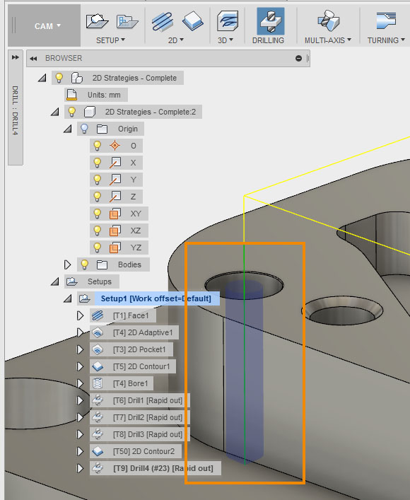
Now when you set up a drill strategy, you’ll see a preview of how far your drill bit is going in relation to the part that you are drilling. This should help you prevent bad things from happening (like not drilling all the way through or holder collisions) so that you get continue on making good things happen (like cranking out more awesome parts).
New! World origin toggle now available in CAM workspace
For those of you that have an an eagle-eye, you may have noticed that visibility for global origin is now also available within the CAM workspace. You no longer have to go back and forth between Model workspace and CAM workspace to manage your global origin. We’ve been testing this and have found some instances where the origin doesn’t show up. If this happens to you, let us know.
New! Stock from Solid now available for rest machining
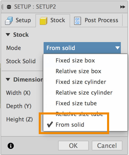
If you’re doing rest machining, you’ll be happy to know that Stock from Solid is now an option within the Stock tab of your setup dialog.
New! Product link field available in the tool library
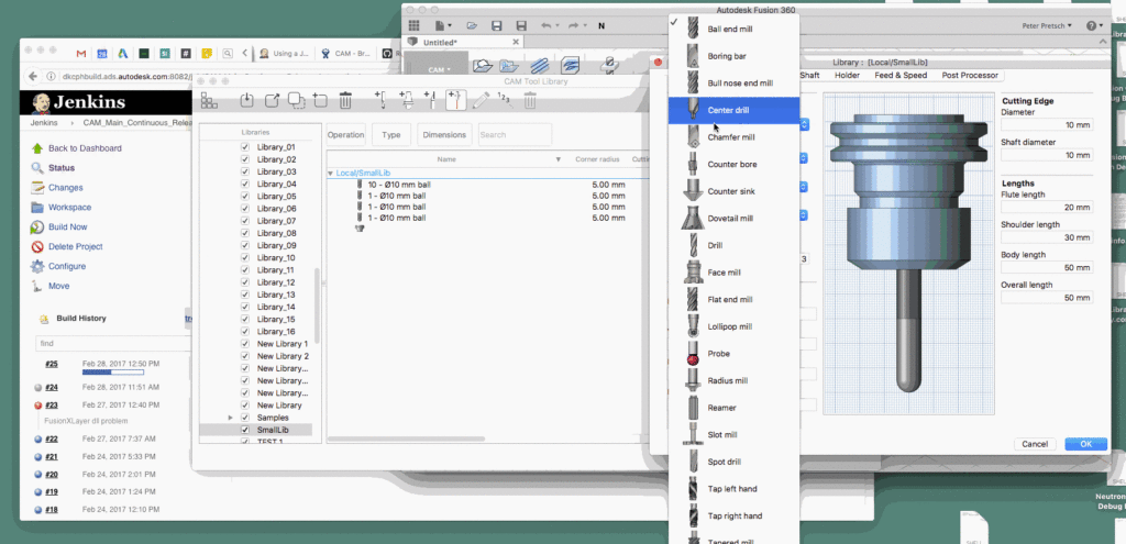
Got the link to where you purchased your sweet tools? Include it as part of your tool properties by entering it in the new Product Link field. Now you can keep track of all your tools and where you got them right within your tool library.
New! 2D cutting sample tools are now available in the tool library
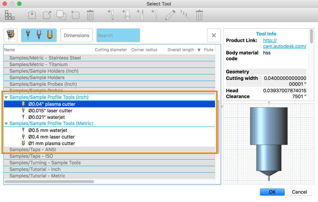
Our bad – apparently these never got added. Now you don’t have to go edit a non-2D cutting tool and pretend like it’s a 2D cutting tool.
New! Updated Post Processors
We updated a bunch of Haas post processors recently. Generic Heindenhain, generic Mach 3 Turning, generic Robodrill, and a couple others also received a bump. Go get ‘em here.
That’s a wrap!
In addition to these new features, we’ve made fixes and improvements in every aspect of the software. Some of these you won’t even notice, and some we’ve specifically followed up with you on the forum. Your participation is always greatly appreciated, and we are looking forward to you feedback. Cheers!
~
Keqing and the Fusion 360 Team
