
[icon name=”bullhorn” class=”” unprefixed_class=””] Special Announcement
As we all deal with the current public health crisis, communities from around the world are coming together to help support those in need, and help protect medical professionals working tirelessly in the field.
[icon name=”heart” class=”” unprefixed_class=””] Free trial now extended through May 31st
To help you get started with design and manufacturing, we’ve extended the duration of Fusion 360’s free trial through May 31st as part of an overall effort across the company to provide you the tools you need to be successful.
[icon name=”arrow-circle-right” class=”” unprefixed_class=””] Learn more
[icon name=”heart” class=”” unprefixed_class=””] Manufacturing Extension now available for everyone through May 31st
As of this update, we’ve also made Manufacturing Extension tools available for everyone through May 31. This includes all the advanced tools currently in the Manufacturing Extension package: Additive Manufacturing, Hole Recognition, Probe Geometry, Surface Inspection, and Steep & Shallow strategies. When you go into the Manufacture workspace, those tools will be enabled in the toolbar and you’ll be able to use them at no cost. [icon name=”arrow-circle-right” class=”” unprefixed_class=””] Learn more
[icon name=”heart” class=”” unprefixed_class=””] Connect with Design and Manufacturing Communities
Many of us on the Fusion 360 team are helping our local communities make personal protective equipment (PPE). If you’d like to help your community, have ideas you’d like to share, or are looking for information on how to get involved, we’ve created a live page a list of organizations you can get involved with, and directions for how to submit your own ideas.
[icon name=”arrow-circle-right” class=”” unprefixed_class=””] Support your communities
V. 2.0.8176 | April 27, 2020
Manufacture
[icon name=”thumbs-up” class=”” unprefixed_class=””] Improved! New Tool Library (Preview)
Turn it on in Preferences > Preview features > Tool library
Manufacture Workspace > Utilities > CAM Tool Library
We’re working hard to build a new tool library that gives a great user experience and allows you to manage and use your tools efficiently. We’d love to hear your feedback on the New Tool Library forum thread!
Invalid Tools
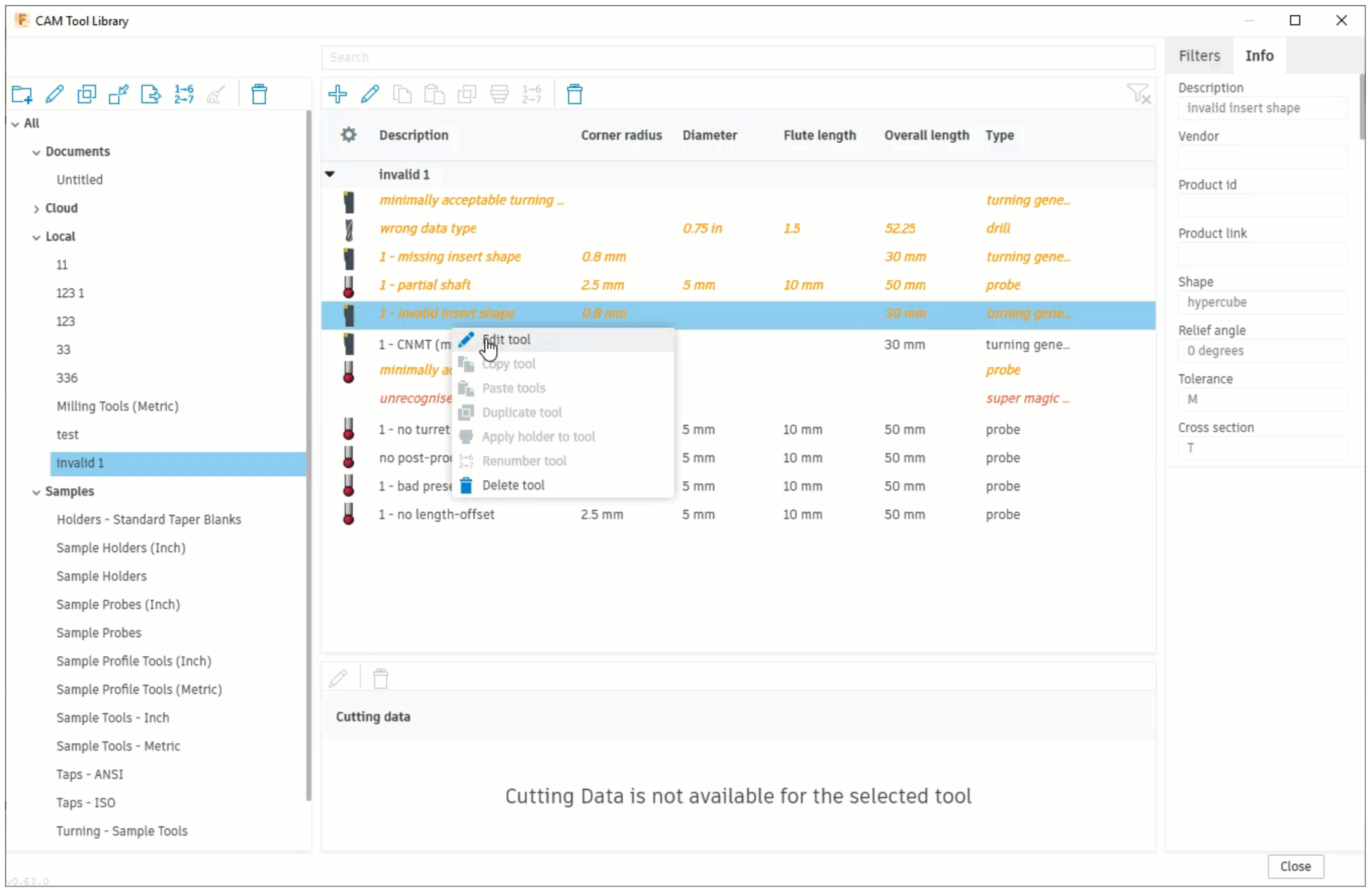
We now handle invalid tools within imported libraries in a way that allows the user to initially identify which tools in the library are invalid. This is achieved through changes to both text type and color. The user then has the ability to edit the tool with missing or incorrect values through the highlighted tab and the invalid field will be identified with a message. Once the field is edited with the correct value the changes can then be accepted and the tool will be valid for use.
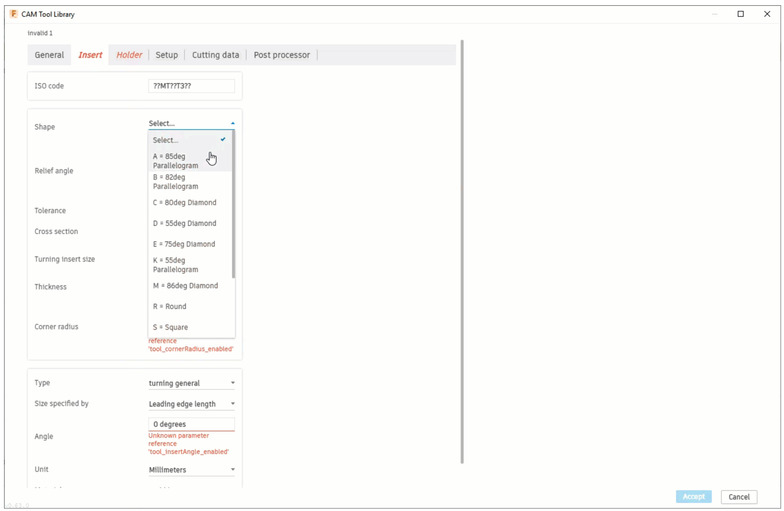
Linked Parameters and Locked Parameters
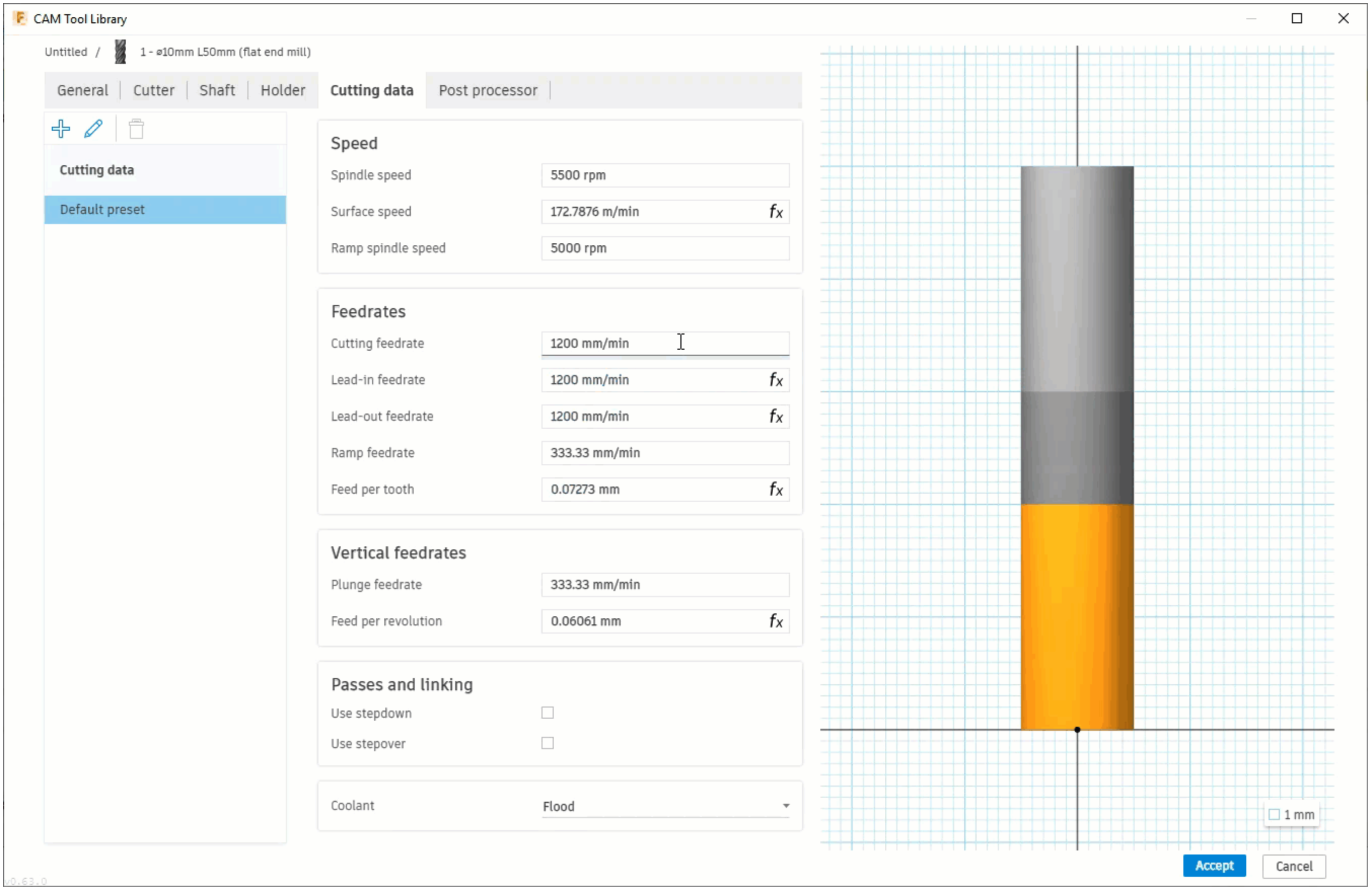
Within the Cutting data tab we have linked feed rates with expressions and added a visual FX symbol to identify which values are linked. Users can click in the field and edit, the driven changes will then be updated in the linked field. The user can choose to break the link by adding a value in the field and the FX symbol will no longer be present.
Length and offset numbers are defaulted to the tool number and this link is indicated by the FX symbol. The user can alter the tool number with the confidence that the offsets will change also. In the event that a different offset number is required then the field can be edited and the FX symbol will no longer be present.
Other Improvements
- Consistency work – We have worked to improve the layout and appearance of the tool library by adding consistent icons, box tabs and indicating active icons in blue.
- Tooltips – To ensure users have the best experience we have added tooltips which not only explain the icons function but also, if the icon is disabled, informs the user what action they need to carry out first.
- Single click edit – When altering a value within a field, feedback from users was that the experience was slow as it involved deleting multiple digits or selecting all the text to delete. The user can now single click on a field and the whole text will be highlighted then edited or deleted without excessive keystrokes.
- Additional Warning – An additional warning is given when a user chooses to delete a library and indicates how many tools are in the library to ensure data is not lost without user confirmation.
[icon name=”wrench” class=”” unprefixed_class=””] [expand title=”Issues Fixed – Click to expand”]
- We fixed an issue where some of you experienced a crash right after a a launching the software.
- csmithQ9RTJ found a bug where if Turning General tools were set to round, M or as a custom insert, it would fail to load in the tool library for both existing and newly created tools. Now doing this will load properly in the tool library.
- We fixed an issue reported by jas.okon where certain turning profile roughing and finishing operations with unequal X and Z finish allowances were not generating correctly.
- As discussed in this thread, we fixed an issue where a username with non-ascii characters caused a crash in starting Adaptive Clearing operation in Manufacturing workspace.
[/expand]
Graphics
A number of you have reported graphics issues ranging from component edges turning white to sketch lines disappearing when creating primitives bodies. We discovered that if you have your Transparency Effect in your preferences set to “Better Display”, something was not working properly. We were able to nip this in the bud and all these issues are not gone.
API
Meeloo told us about an issue in our API where apparently bunch of libs were missing from the code. They are now back.
V.2.0.8156 | April 15, 2020
Some of you reported that when you expanded the Create drop-down menu in the Design workspace, the menu doesn’t actually drop down, it flew up! This has now been resolved.
V.2.0.8111 | April 13, 2020
[toc]
Data Management
[icon name=”star” class=”” unprefixed_class=””] New! Manage file sharing control across your team
Fusion Team > Profile > Admin (if applicable) > Team Settings > File Sharing

Security is fundamental to us, and we heard that you would like more control over what is shared externally. Previously, you would have to navigate to every single file in Fusion Team to disable the share option. Now, we have added the ability for the Fusion Team administrator to turn on/off all file sharing from the administrative console.
[icon name=”file-text” class=”” unprefixed_class=””] See help documentation
[icon name=”star” class=”” unprefixed_class=””] New! Ability to leave a team
Fusion Team > Profile > Settings > Default team
If you’re working in a large group of team members across multiple teams (think classrooms), managing who comes and goes can be quite the daunting task for a team admin. Now team members have the ability to leave a team on their own, without constantly relying on the team admin to do it for them.
[icon name=”file-text” class=”” unprefixed_class=””] See Help Documentation
[icon name=”thumbs-up” class=”” unprefixed_class=””] Improved! Open in Fusion 360 from Web Viewer for team members
To share a design: Data Panel > Project > Design > Right-click > Share Public Link
To view a design via web viewer: get the Public share link and open in your web browser
Back in October of 2019, we introduced the enhancement of opening a shared design via the web viewer directly within Fusion 360. We’re now rolling out a few more improvements to this experience, specifically for those sharing designs to their team members with access to the project these designs are coming from.
Save markups directly to the design
If you are logged into Fusion Team and have access to the team project (from which the design that was shared to you originates from) you’ll be able to view and save markups and comments directly to the design. If you’re not logged into Fusion Team or do not belong to that team project, you’ll be able to save markups as a snapshot.
Supports Assemblies and 2D Drawings
Previously we only supported single design files in our Open in Fusion 360 workflows.
Open in Fusion 360 of the share page now supports Drawings as well as Designs with references. This will enable you to open assemblies which reference other Fusion 360 components or drawings.
[icon name=”thumbs-up” class=”” unprefixed_class=””] Improved! Open button now embeddable in HTML along with viewer
From the Data Panel: Project > Design > Version number > View Details on Web > Share icon > embed code
We have updated the embedded snippet of Fusion 360 to feature the Open in Fusion 360 button as well. This enables you to open an item in Fusion 360 directly from the web page where the embedded snippet was embedded, like the example shown below.
[icon name=”check-circle” class=”” unprefixed_class=””] Inventor 2021 file format Solid Edge 2020 now supported
Some of you have reported that you were not able to open Inventor 2021 files nor Solid Edge 2020 files in Fusion 360. We’re glad to report that we’ve updated our translation pipeline to support importing of these file formats.
Usability
[icon name=”exclamation-triangle” class=”” unprefixed_class=””] As of May 2020, Fusion 360 no longer supports macOS 10.12. If you want to continue using Fusion 360, please upgrade to 10.13 or newer. See our support article for more details.
[icon name=”thumbs-up” class=”” unprefixed_class=””] Improved! Component Color Cycling available in more workspaces
Component Color Cycling found under Inspect > Component Color Cycling (SHIFT + N)
If you had Component Color Cycling is turned on, previously it was only visible in the Design workspace > Solid tab. Now these colors will also show for environments like Sketch, Form, Mesh, Surface, Sheet Metal, and other workspaces like Animation, Simulation, and Manufacture. Workspaces like Generative Design and Render will override these colors due to the specific nature of their workflows.
[icon name=”wrench” class=”” unprefixed_class=””] [expand title=”Customer Reported Issues Fixed – Click to expand”]
- HughesTooling went above and beyond to find what has now become an improvement to all other Fusion 360 display environments that are not Photo Booth (the default). Now all the other environments have the same number of colors available in Component Color Cycling.
- Many of you using Fusion 360 on macOS have chimed in on the forum and told us about an issue where Fusion 360 became unresponsive when you toggle between active application windows and go back to it. We’ve been chasing this issue for a while and are glad to report that we believe it has been resolved.
- A few years ago Demetriades.alexandros found a bug lingering in the Curvature map analysis where the input box cuts off some of the digits. Now the input box shows all the allowed digits.
- We discovered that applying a Draft analysis on certain geometry causes the surface to flicker. That’s definitely not supposed to happen, and we made sure it doesn’t anymore.
- Etfrench told us about an issue where measurements he made on his design using the Measure command became barely visible in certain viewing angles running in the Infinity Pool environment. We improved this so that the measurements are visible regardless of angle and display environment you run in.
- francisco2N33A found a bug affecting how Fusion 360 calculates the Moment of Inertia. He even did the due diligence and cross-checked the math, and proved that it was a bug. We got the math sorted out.
- If you were running Shaded with a hidden edge display setting on a Windows 10 machine, some hidden edges weirdly disappeared after you edited a model. What was even worse was that once this happened, those hidden edges cannot be displayed again. This is now fixed and those edges won’t disappear anymore.
- www.timmilo found an issue with how Manufacture Extensions dialog handled German words, making them too small and consequently made it impossible to purchase the extensions. We gave him a work-around while we worked on getting this fixed, and now it is.
- Kodenma from Japan ran into a bug with the Export Flat Pattern as DXF tool where it was generating invalid files when he was using the Japanese version of Fusion 360. Gomen nasai! We got this fixed.
- When you tried to use the Capture Image tool, checking and then unchecking the “Save to My Computer” option in the dialog inadvertently blocked your ability to also save the image to your project in the cloud. We fixed this so you can still save to the project independent from saving locally.
[/expand]
Sketching & Modeling
[icon name=”thumbs-up” class=”” unprefixed_class=””] Improved! Ability to select a row of tangency handles
Behavior found within Design > Create Form > Edit Form while selecting Tangent Handles
Previously it was pretty challenging to select a series of tangency handles (green dot) and have them grouped as a single selection set. We’ve now expanded our selection capabilities, allowing you to select them just like how you would select multiple vertices (grey dot).
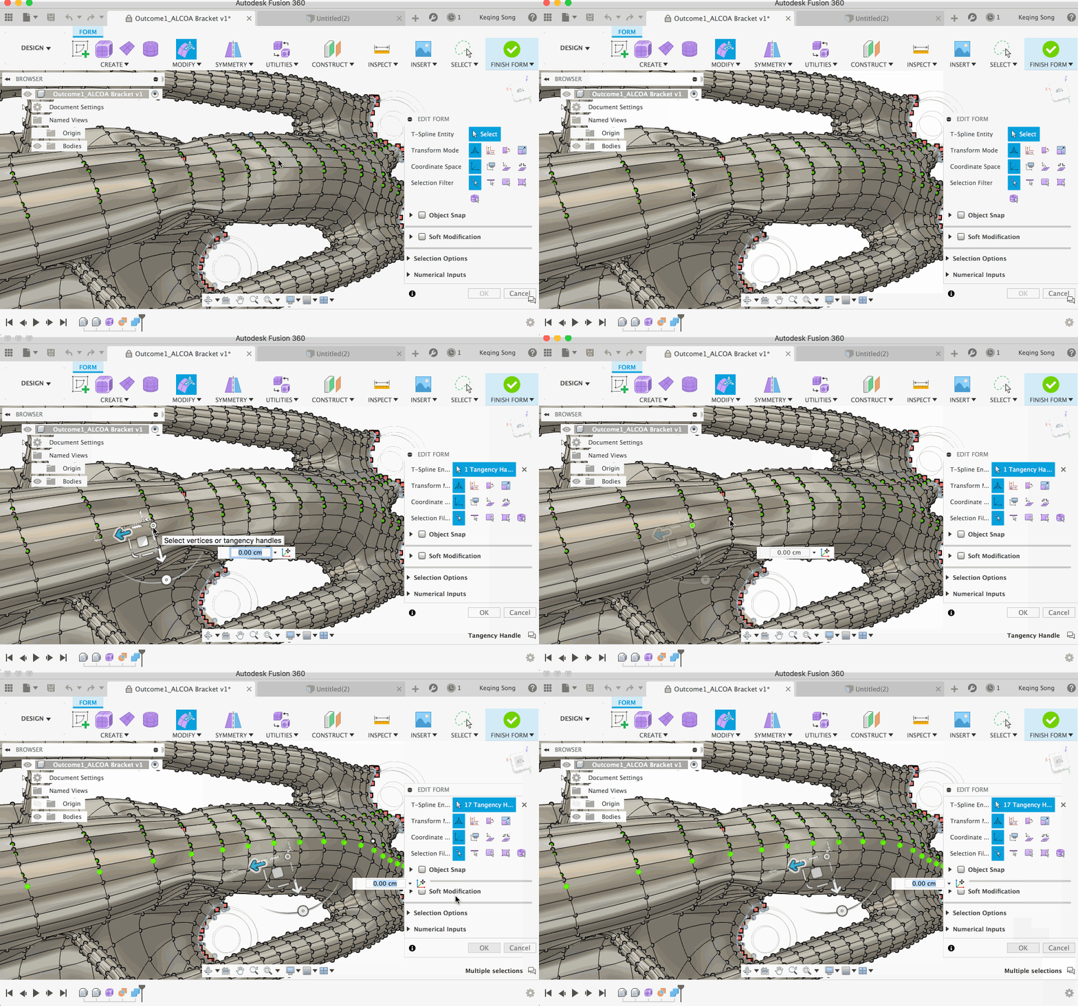
You can select a tangency handle, and then double-click a neighboring tangency handle to select the entire row. You can also select a tangency handle, double-click on a non-neighboring one and all the tangency handles in-between will be selected.
You can use existing selection options listed below to grow or shrink your selection set:
- Loop Selection (Alt or CTRL+P) (also support click+double-click method, as shown above)
- Loop Grow Selection (Alt or CTRL+O)
- Loop Shrink Selection (Alt or CTRL+I)
- Invert Selection (Alt or CTRL+N)
Range Selection (Alt or CTRL+M) (also support click+double-click method)
[icon name=”wrench” class=”” unprefixed_class=””] [expand title=”Customer Reported Issues Fixed – Click to expand”]
- You know how the Move command also enables you to make a copy of the thing you’re trying to move? Well Hoegge told us a while back that this didn’t work with Sketch > Text entities. Sorry for the inconvenience! This is now fixed.
- alfredMMQC9 ran into a scenario where the Extrude command was incorrectly assuming that he wanted to extrude a sketch that had its visibility turned off. Now if sketches are not visible then they will not be automatically selected when Extrude is invoked. If multiple sketches are visible and the user selects extrude, then none of them will be automatically selected.
- Nathanekema was running into an issue where he wasn’t able to unstitch the surfaces on his design together using the Unstitch command found in the Surface tab. We found some questionable entries in the back-end code and sorted it out, now it should unstitch without issues.
- Lonnie.Cady gave us a shout regarding an inconsistency around how Fusion 360 colors projected lines and projected construction lines. Long story short, now when you convert a projected line, it is no longer black; it is a purple dashed line.
- We heard reports of the timeline behaving erratically, where single stepping through the history or doing a Compute All would sometimes omit certain steps, as if they never happened. Of course, this is wrong. We tidied up the timeline so now this issue won’t happen again.
- When mah6786 was creating a group in the timeline, he included a “/” in the name of the group, like “Motor/Gear Assy”. Turns out naming a timeline group with a slash made the timeline group undeletable. Thanks to mah6786’s forum post, you’re now able to delete timeline groups with names that include the backslash.
- We’re glad to report that we finally fixed an old issue regarding Plane Along Path, where the Sketch coordinate system was not updating correctly when you dragged the path that your construction plane was based on.
- Last year TrippyLighting told us about a problem where he was unable to create a surface patch on his surface model with the Patch tool. We recently did some work in this area and were able to get this issue resolved – Patch tool should now work as expected.
- Laughingcreek found a wonky issue with the Loft command, where changing the curvature conditions of the rail in his Loft command from “connected” to “curvature” made the solid loft incorrectly turn into a surface loft.
- TrippyLighting also ran into a bug in Loft where one of the 2 rails he used for his loft disappeared from the dialog when he went back to edit the Loft. Sorry about that – both issues reported by Laughingcreek and TrippyLighting have been fixed.
- We resolved an issue raised by HughesTooling regarding visibility and activation of a new component. Fusion 360 was incorrectly telling you that your newly created component was not visible, even though the parent component and this new component was visible; it was just not activated.
- KMP ran into an issue where a part that was derived unexpectedly disappeared when they performed a Compute All. We tweaked the code and how Compute All should work as expected without any derived parts disappearing.
- RectangularPatternFeatures.add API failed to create a Rectangular pattern when the body resided in any component other than the root component of the document. It worked fine on bodies created within the root component. Now the API works as expected.
[/expand]
Generative Design
[icon name=”star” class=”” unprefixed_class=””] New! Show tools in Outcome View
Generative Design workspace > Explore Environment > Outcome View mode > Show panel
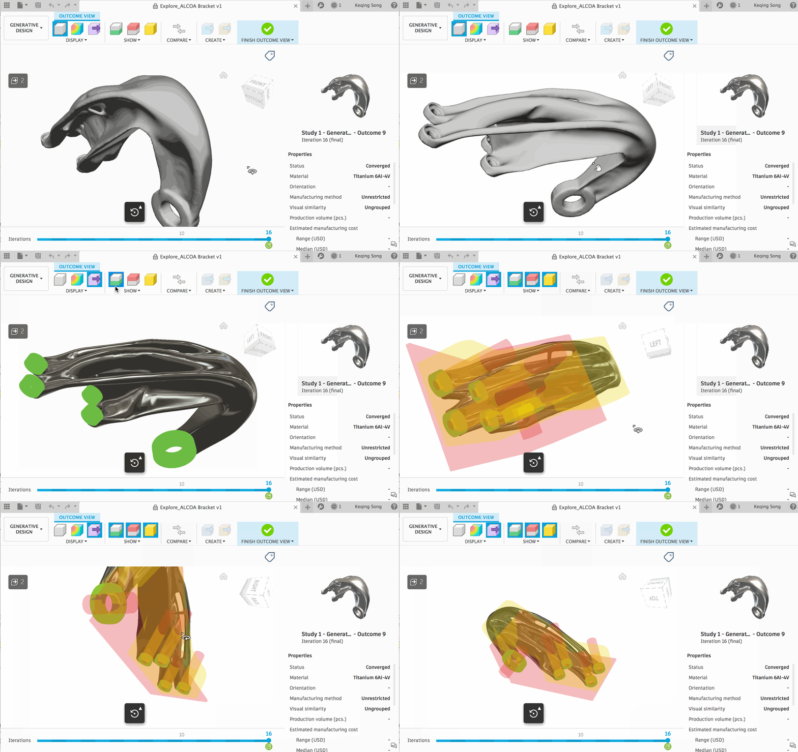
When you’re looking at the outcome view of a specific iteration, you can now go to the new Show panel in the Outcome View toolbar and toggle Preserve Geometry (green), Obstacle Geometry (red), and the Starting Shape (yellow, and only if the design started with one), as well as the Design Preview display, showing you what the outcome would look like if you downloaded it.
[icon name=”file-text” class=”” unprefixed_class=””] See Help Documentation
[icon name=”thumbs-up” class=”” unprefixed_class=””] Improved! Minimum Wall Thickness criteria for 2.5 Axis milling
Generative Design workspace > Design Criteria Panel > Manufacturing > Milling > 2.5-axis
When you’re setting up your 2.5 axis milling manufacturing criteria for Generative Design studies, you now have the ability to define a minimum wall thickness value, giving you a more control over the outcomes.
[icon name=”file-text” class=”” unprefixed_class=””] See Help Documentation
[icon name=”thumbs-up” class=”” unprefixed_class=””] Improved! Visual Similarity and Manufacturing Cost clustering now available for existing studies
Generative Design workspace > Explore Environment
The Explore view in Generative Design gives you the ability to compare and contrast a cluster of outcomes based on visual similarities as well as manufacturing cost estimations. This was previously only available on new studies created. Now the functionality is available on existing studies as well.
[icon name=”file-text” class=”” unprefixed_class=””] See Help Documentation
[icon name=”wrench” class=”” unprefixed_class=””] [expand title=”Issues Fixed – Click to expand”]
- Outcome filters can quickly become visually cluttered if all of them were expanded by default. We’ve tweaked the behavior so that they are now collapsed by default. Objective ranges will remain expanded since they provide essential information upfront for you to better explore your outcomes.
- Previously the word “Generative” was placed in the model name as well as the study name. Now we’ve removed it from the study name to reduce redundancy and length of the name.
[/expand]
Electronics
[icon name=”star” class=”” unprefixed_class=””] New! Quick Route Guided
Electronics Design > 2D PCB > Quick Route > Quick Route Guided
The new Quick Route Guided command allows you to route the airwires between multiple pads of devices in 2D PCB, by defining a guided drawing path.
To use the Quick Route Guided command, select the device pads that originate the route, and then right click to finish pad selection. Left-click to begin drawing a guide path that you intend for the routed wires to follow.
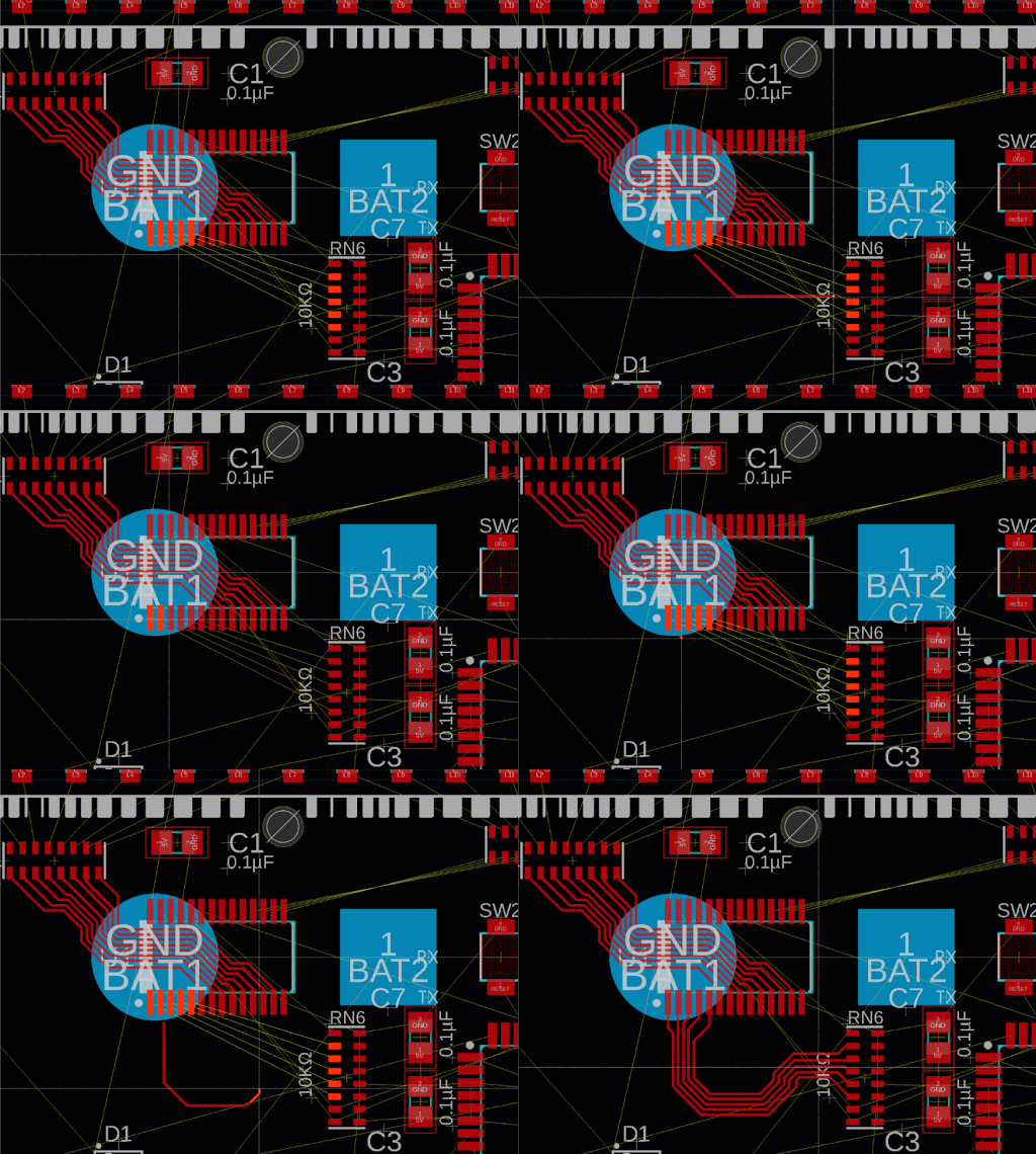
While drawing the guide path, you may right click to change the guide wire bend style. Double click to finish drawing the guide path and then press Enter to complete the routing of the wires to their target pads. You can change the routing layer at any time prior to completing the route.
The Quick Route Guided command allows you to quickly and easily route multiple airwires on a single layer, in configurations where the routed wires are generally parallel and can easily conform to your guided path.
[icon name=”wrench” class=”” unprefixed_class=””] [expand title=”Issues Fixed – Click to expand”]
- Hot keys didn’t work very well in Electronic Design’s new Schematic, 2D PCB, and Library environments since the command line bar was constantly stealing focus. Now it doesn’t steal focus anymore, and all the keyboard shortcuts specific to Electronics Design work as expected. For users that prefer the old behavior, you can access it by enabling the Legacy command line focus option from Preferences > General > Electronics > Misc.
- We fixed an issue that was causing Fusion 360 to become unstable when we tried to create a 3D PCB based on edits we made to a 2D PCB and schematic.
[/expand]
Rendering & Animation
[icon name=”wrench” class=”” unprefixed_class=””] [expand title=”Issues Fixed – Click to expand”]
- We fixed an issue in our cloud rendering engine where the “Water – Calm Sea” environment background was getting incorrectly rendered in the final result of the rendering. Now it should render correctly.
- Mda reached out to us about how he wasn’t able to use the Selection Sets he created in the Design workspace in the Animation workspace. We tested this in the recent builds and were no longer able to reproduce the error and have confirmed that this has been resolved.
- Apparently if you used the background local rendering as well as cloud rendering, the rendering engine mistakenly rendered a ground plane in the frame even though you didn’t put one there. We crushed this bug so that background local rendering and cloud rendering render the scene as expected.
- Treatrick_d in the Japanese forum told us about an odd behavior he noticed when he was rendering his model with a glass material called “Base material – Blazing”. Turned out that when local background rendering, the result showed black and yellow squares, as if the renderer couldn’t process the material. We resolved this issue and now the material comes through correctly.
[/expand]
Simulation
[icon name=”star” class=”” unprefixed_class=””] New! Electronic Cooling Preview
Simulation Workspace > New Study > Electronics Cooling (Preview)
Turn it on in the Preview section of your preferences
Electronics Design in Fusion 360 enables you to design schematics, 2D PCB layouts, as well as the 3D PCB board in context to your overall 3D design all in one solution. One of the things we are all familiar with is that electronics generate heat, and components overheating can lead to serious consequences. This is why we’ve been working technology that will allow you to simulate cooling studies so you can design your electronic products for optimal performance.
With Electronics Cooling Preview enabled, you’ll see the new option in the New Study dialog in the Simulation workspace. Electronics Cooling studies allow you to see air movement in the design, find hot spots where components are exceeding critical temperatures, and view the results visually.
[icon name=”file-text” class=”” unprefixed_class=””] Check out our recent blog post for videos on how to get started.
[icon name=”comment” class=”” unprefixed_class=””] Talk to us about what you think
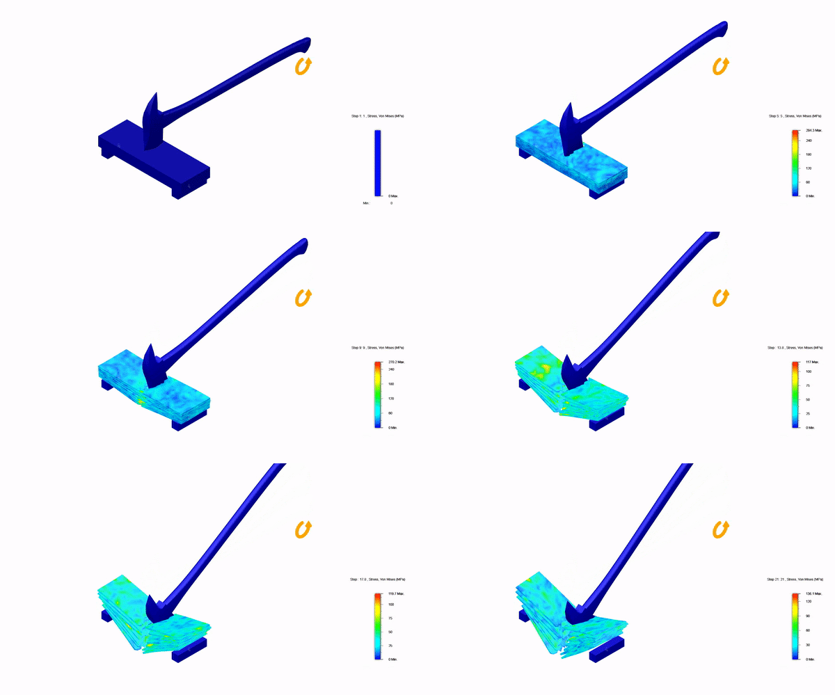
[icon name=”star” class=”” unprefixed_class=””] New! Initial Angular Velocity Load in Event Simulation Study (Preview)
Simulation workspace > Event Simulation Study > Setup Tab > Loads > Initial Angular Velocity
The Initial Angular Velocity is used to apply rotational motion to a body at the start of the analysis.
[icon name=”star” class=”” unprefixed_class=””] New! Prescribed Rotation Constraint Event Simulation Study (Preview)
Simulation workspace > Event Simulation Study > Setup tab > Constraints > Prescribed Rotation
The Prescribed Rotation is used to constrain a body to a rotational motion. The constraint could be in the form of an Angle, Rotational Velocity or Rotational Acceleration.
[icon name=”star” class=”” unprefixed_class=””] New! Quasi-Static Analysis in Event Simulation Study (Preview)
Simulation workspace > Event Simulation Study > Setup tab > Manage > General > Movement > Quasi-static (No inertia)
By Switching the “Movement” from Dynamic to Quasi-static (no inertia) we can obtain an approximate Quasi-static solution using the Explicit solver in Event Simulation. To obtain an approximate quasi-static solution in our explicit dynamics algorithm we seek to make the magnitudes of the kinetic energy and viscous dissipation in the solution small compared to the magnitude of the internal energy and external work. We can do this by picking the duration of the event to be long enough that the kinetic energy is a small fraction of internal energy. This is somewhat subjective and usually the duration is chosen in a trial-and-error process to obtain kinetic energy somewhere in the 1 to 2 percent range of the internal energy.
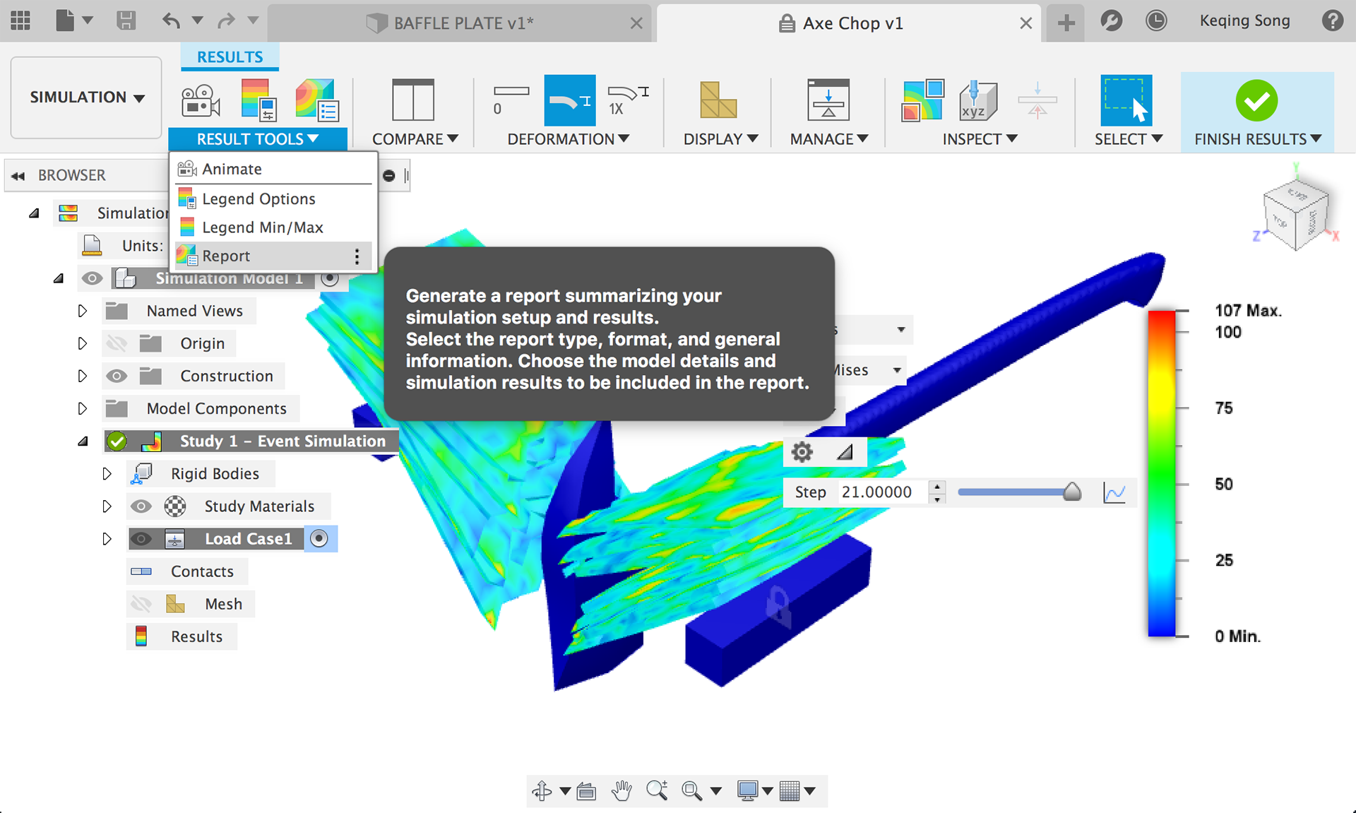
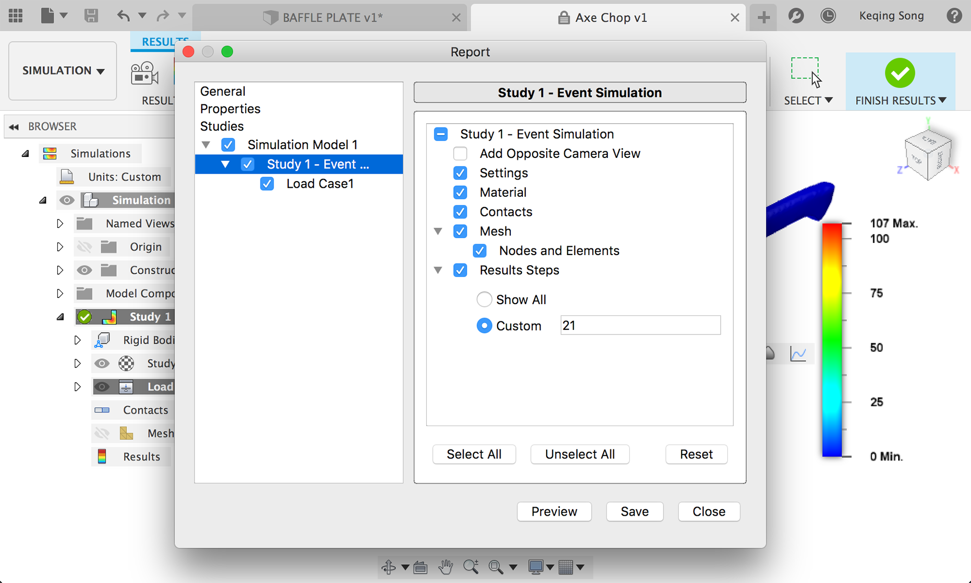
Improved! Result Reports now include Event Simulation studies
Simulation > Event Simulation (preview) > Solve – if the results show results, Report is under the Result Tools panel.
Previously if you created a Simulation result report, it didn’t include any Event Simulation results (if you solved for some). Now when you generate a report, the report will include Even Simulation results as part of it.
Fixed: Advanced Materials Properties issue on macOS
We fixed a crash issue on macOS that was being triggered when you tried to invoke the Advanced Materials Properties in the Simulation workspace.
Manufacture
[icon name=”heart” class=”” unprefixed_class=””] As of this update, we’ve made Manufacture Extension tools available for everyone to try through May 31. When you go into the Manufacture workspace, those tools will be enabled in the toolbar and you’ll be able to use them at no cost.
[icon name=”star” class=”” unprefixed_class=””] New! Toolpath Trimming now available as a Manufacturing Extension
Manufacture Workspace > Milling > Modify > Trim
This feature allows you to trim unwanted regions of a milling toolpath that are inside or outside a sketched boundary. The Trim feature will automatically generate new leads and links around the trimmed region without the need to regenerate the entire toolpath.
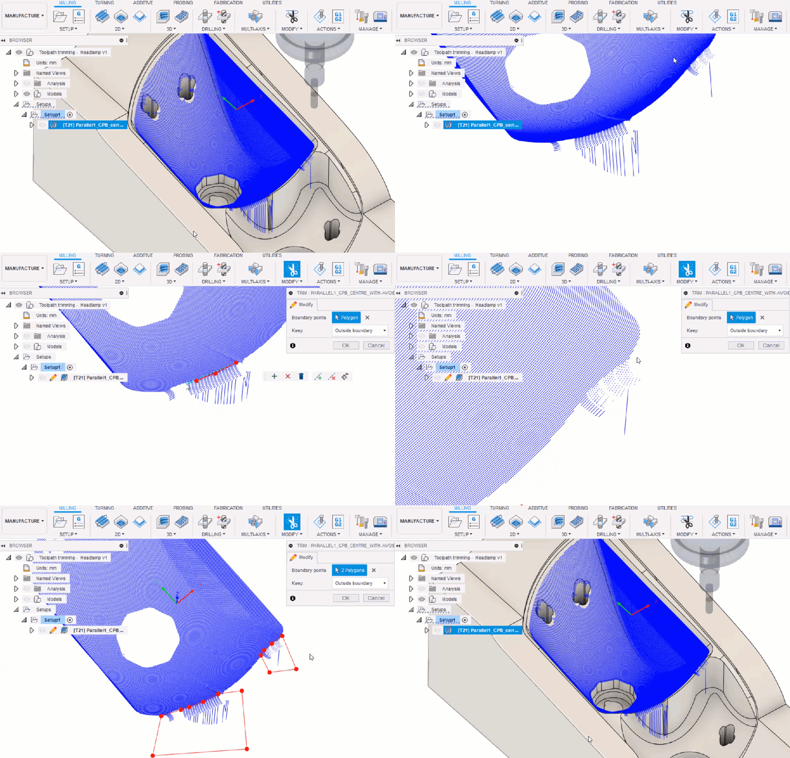
All completed toolpath modifications are displayed in the toolpath timeline. Here, you can Right Mouse Click on a specific Trim in the timeline and either Delete or Edit the modification.
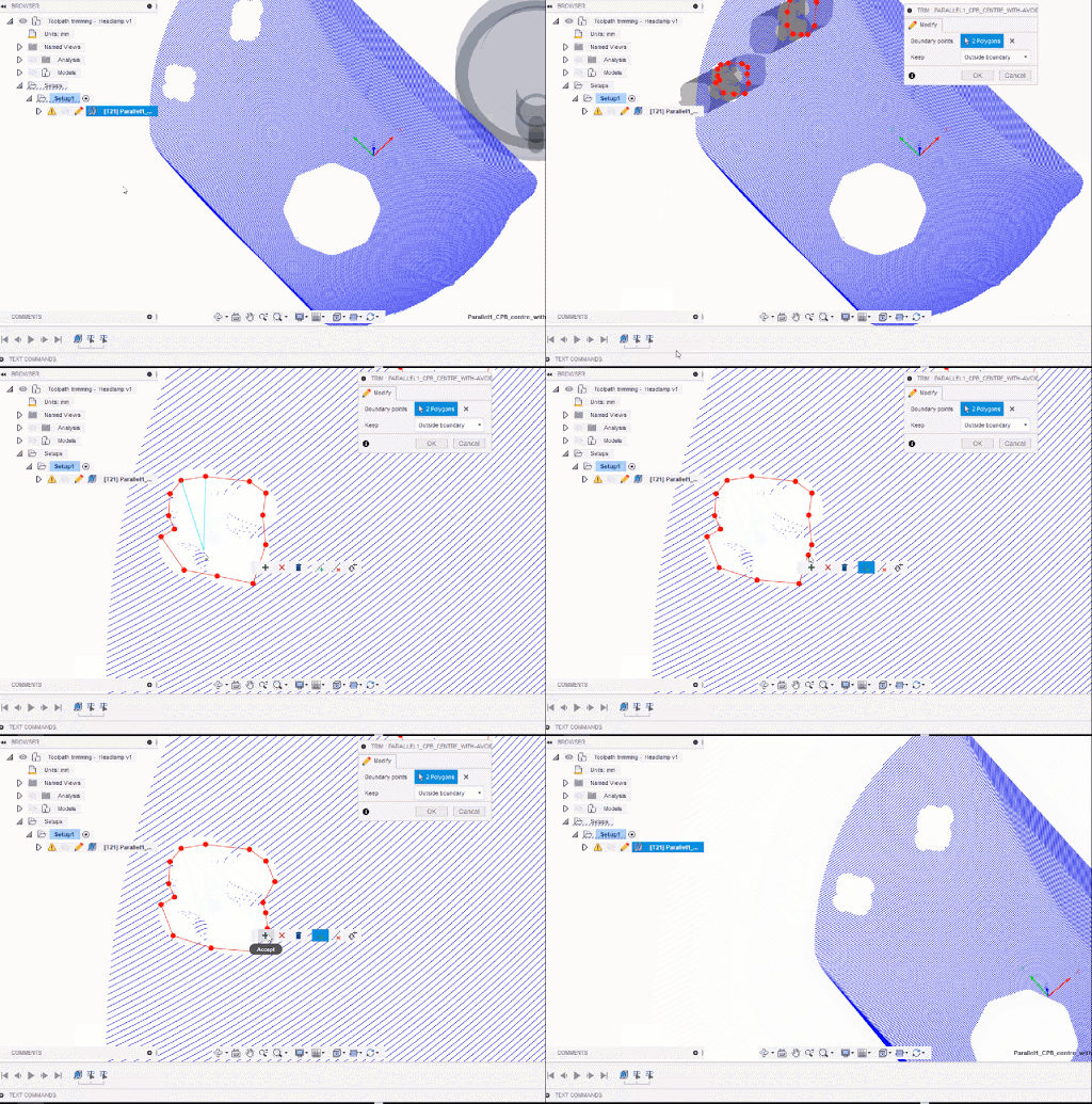
Note: Trimming is not currently available for certain 2D milling toolpaths ( 2D Adaptive Clearing, 2D Pocket, Slot, Thread, Bore, Circular, 2D Chamfer) and certain 3D milling toolpaths (Adaptive Clearing, Pocket Clearing, and Horizontal). In addition, you cannot currently trim a toolpath that has Compensation Type set to In Control, Wear, or Inverse Wear.
[icon name=”file-text” class=”” unprefixed_class=””] See Help Documentation
[icon name=”play-circle” class=”” unprefixed_class=””] Detailed demonstration of Toolpath Trimming
[icon name=”comment” class=”” unprefixed_class=””] Talk to us about it
[icon name=”star” class=”” unprefixed_class=””] New! 4 axis Rotary milling now available as a Manufacturing Extension
Manufacture Workspace > Milling > Multi-Axis > Rotary
The Rotary strategy uses the 4th axis on your machine tool to cut parts where continuous rotary motion is beneficial. It is best used when machining revolved parts, or any part with a centerline axis.
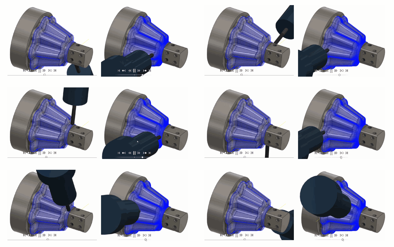
The Rotary strategy generally creates up to 360° rotary motion, but you can also specify an angular range to machine a limited section of your part. Depending on your part and machine tool, choose between the Spiral (left), Line (right), or Circular rotary toolpath styles.
[icon name=”file-text” class=”” unprefixed_class=””] See Help Documentation
[icon name=”play-circle” class=”” unprefixed_class=””] Detailed demonstration of Rotary milling
[icon name=”comment” class=”” unprefixed_class=””] Talk to us about it
[icon name=”star” class=”” unprefixed_class=””] New! Simultaneous 5 axis for the Steep and Shallow now available
Manufacture Workspace > Milling > 3D > Steep and Shallow > Tool Axis
Steep and Shallow is part of the Manufacturing Extension
You can enhance your steep and shallow toolpath to use 5-axis machining and collision avoidance.
- 5-axis controls are about defining the orientation of your tool to machine the part in the most efficient way.
- Collision avoidance is about controlling and defining what your tool should do to avoid Shaft and Holder collisions. As collisions are avoided, you are able to reach more areas of a part and machine more complex parts.


Machining using 5-axis can benefit you by:
- Reducing the number of Setups required – you can machine an entire part in a single Setup using 5-axis machining. Machining without using multiple Setups results in a reduced likelihood of errors related to Setups.
- Being able to use shorter cutting tools – Shorter cutting tools have less likelihood of deflection during machining, providing you with a better surface finish on your part.
- Using the form of the tool to cut more efficiently – When using the Lead and Lean tool axis, you can cut with the side of the tool or the leading edge of the tool to improve the efficiency of your toolpath
[icon name=”file-text” class=”” unprefixed_class=””] See Help Documentation
[icon name=”play-circle” class=”” unprefixed_class=””] See detailed demonstration of the steep and shallow 5 Axis capability
[icon name=”comment” class=”” unprefixed_class=””] Talk to us about it
[icon name=”thumbs-up” class=”” unprefixed_class=””] Improved! Interactive way to browse through layers in Additive Manufacturing.
Manufacture workspace > Additive tab > Actions Panel > Simulate Additive Toolpath
With the March release, we expanded our 3D printing functionality by adding Fused Filament Fabrication (FFF) slicing. Prior to that, you could set up 3D prints for Metal Selective Laser Sintering (SLS) in Fusion 360 Manufacture Extension .Both of these technologies require you to slice the geometry to create and visualize the toolpath.
We made this visualization more interactive. As you enter the “simulate additive toolpath” dialog, we now display an orange slice plane that you can drag up and down the Z axis and visualize the toolpath as well as critical information such as layer number and Z height.
[icon name=”thumbs-up” class=”” unprefixed_class=””] Improved! Setup Sheet Configurations
Manufacture workspace > Actions panel > Setup Sheet
With the March release, we introduced a new way to save and access setup sheets generated from NC Programs in Fusion 360 and Fusion Team. We’ve made these new setup sheets more flexible, adding with this release the ability to select from a number of predefined setup sheet configurations in Fusion and Fusion Team.
[icon name=”thumbs-up” class=”” unprefixed_class=””] Improved! Sync visibility with active setup
Navigation bar > Sync visibility with active setup
This improvement to “Sync visibility with active setup” function prioritizes the ‘hiding’ of components over bodies when a new setup is activated, reducing the ‘carry-over’ of visibility changes to the Design workspace. Ace.
[icon name=”thumbs-up” class=”” unprefixed_class=””] Improved! Turning Profile Roughing Canned Cycles
Turning tab > Turning panel > Turning Profile Roughing
The Turning Profile Roughing strategy now supports “in computer” compensation for G71 and G72 canned cycles.
When the “Use Canned Cycle” option is checked, the user now has two compensation type options which control how the canned cycle profile is output to the control.
- In computer (new behavior): This option allows the user to output a canned cycle profile already compensated for the tool nose radius. The benefit of this approach is, the user does not need to enter the tool nose radius compensation at the control.
- In control (existing behavior): This option is existing behavior which allows the user to output a canned cycle profile uncompensated for the tool nose radius. In this case the user needs to enter the tool nose radius compensation value at the control. The benefit of this approach is, the user can run the exact same NC code to machine the part using a different tool simply by entering a different tool nose radius compensation value at the control without having to regenerate the toolpath in Fusion 360.
[icon name=”thumbs-up” class=”” unprefixed_class=””] Improved! Turning Parting Reduced Spindle Speed
Turning tab > Turning panel > Turning Part
The parting operation previously supported a reduced feed rate at a user-specified radius away from the center by turning on the “Use reduced feed” option. Now users can also specify a reduced spindle speed when this option is turned on. Programming a reduced spindle speed just before the part is cut off allows the part to be safely separated from the stock without damaging it.
Note: Reduced spindle speed for parting is currently only supported when the “Use Constant Surface Speed” option is turned off.
[icon name=”thumbs-up” class=”” unprefixed_class=””] Improved! Find, renumber, and delete tools in Tool Library Preview
Turn it on in Preferences > Preview features > Tool library
Manufacture Workspace > Utilities > CAM Tool Library
We’re working hard to build a new tool library that gives a great user experience and allows you to manage and use your tools efficiently.
Find tools based on setups and operations
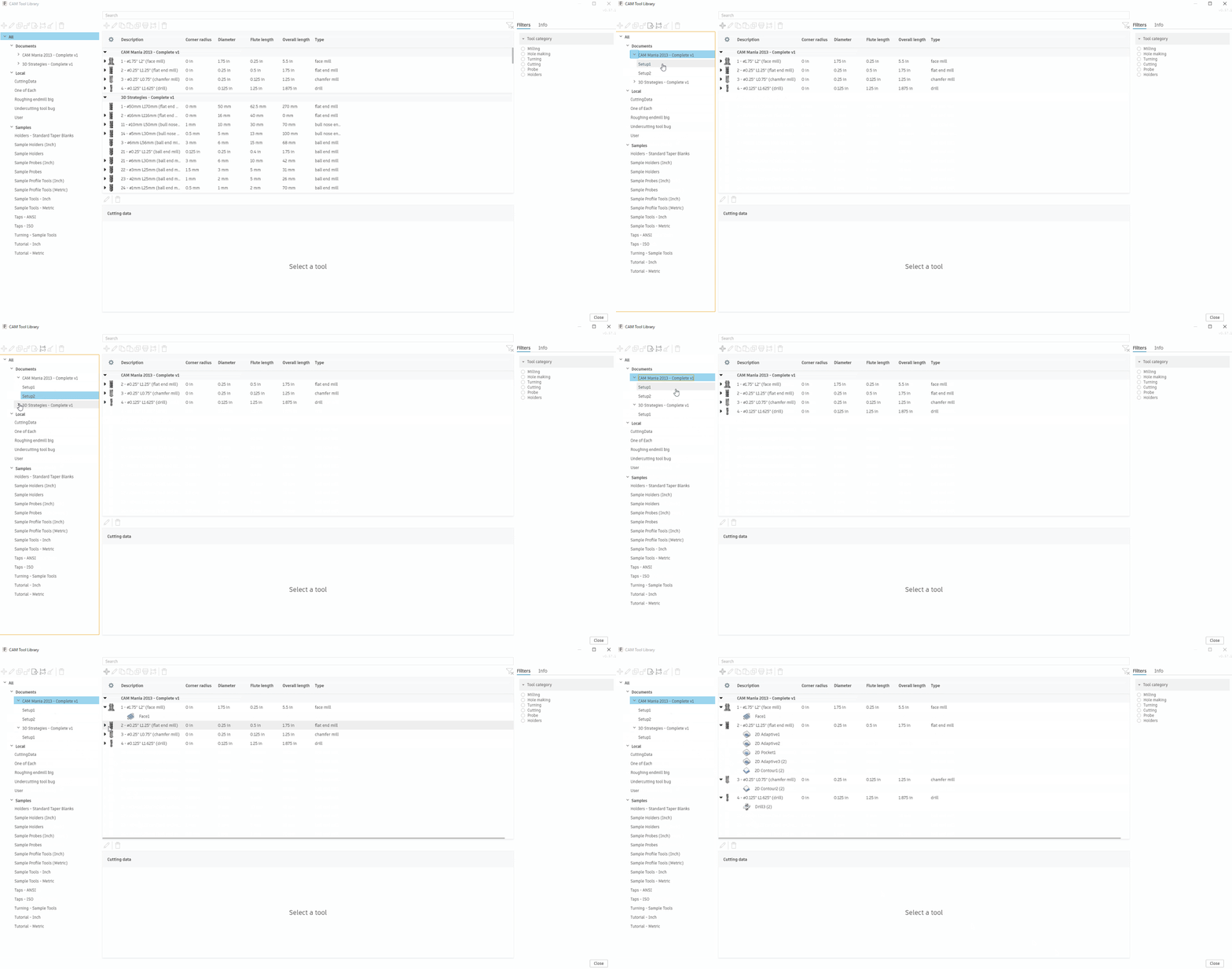
We’ve added a list of setups under the document library to help you quickly find tools associated with a setup. Clicking on a setup in the tree will filter the tool list to show only tools in that setup. In the main tool list, we’ve made tools used in operations expandable; expanding a tool will show all the operations it is used in.
Renumber tools
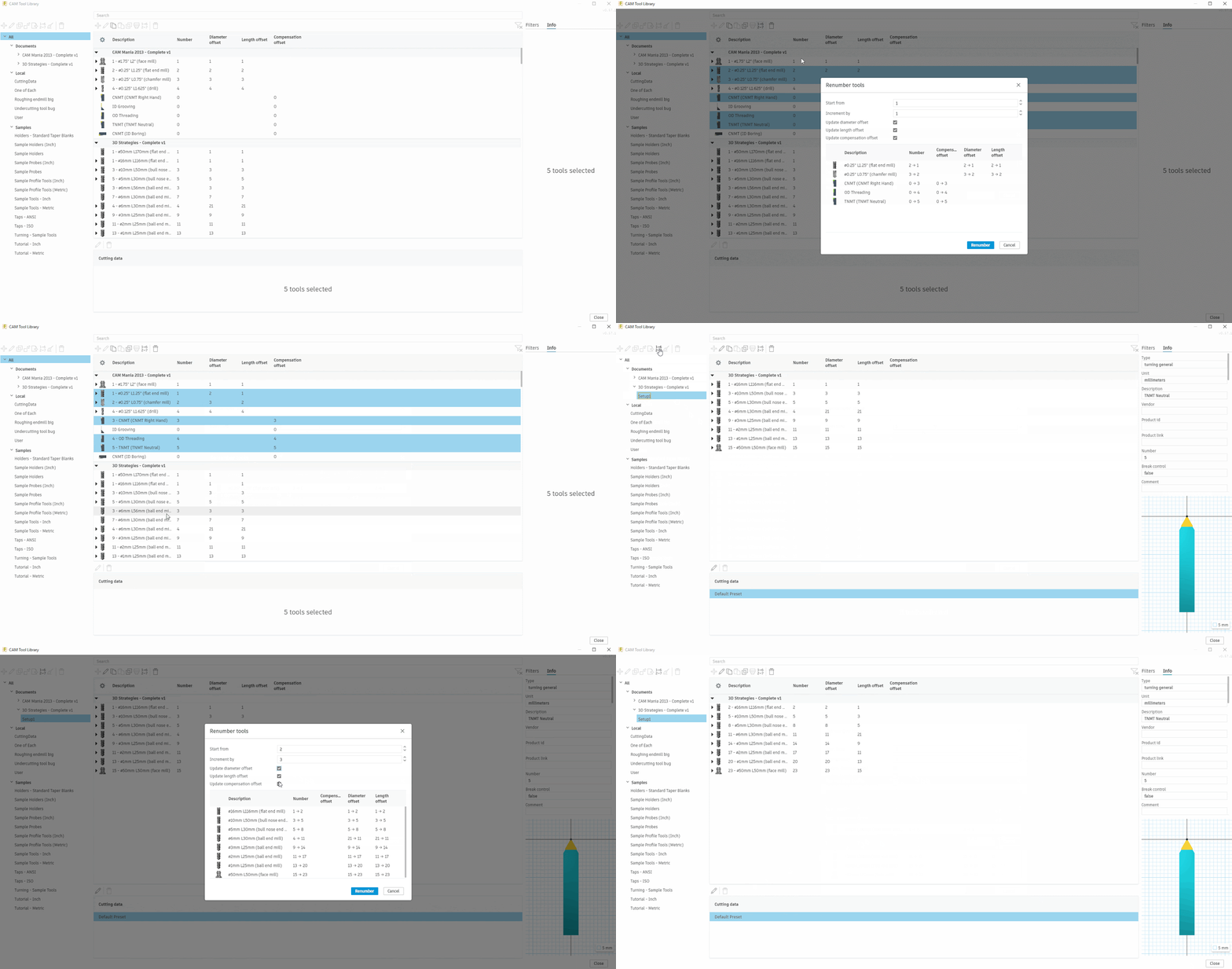
You can now renumber a selection of tools quickly using the Renumber tools button. To renumber a set of tools, select the tools you’d like to renumber in the tool list then press Renumber tools above the tool list. To renumber all tools in a library, select the library in the tool library tree on the left-hand side then use the Renumber tools button above the tool library tree.
Remove unused tools
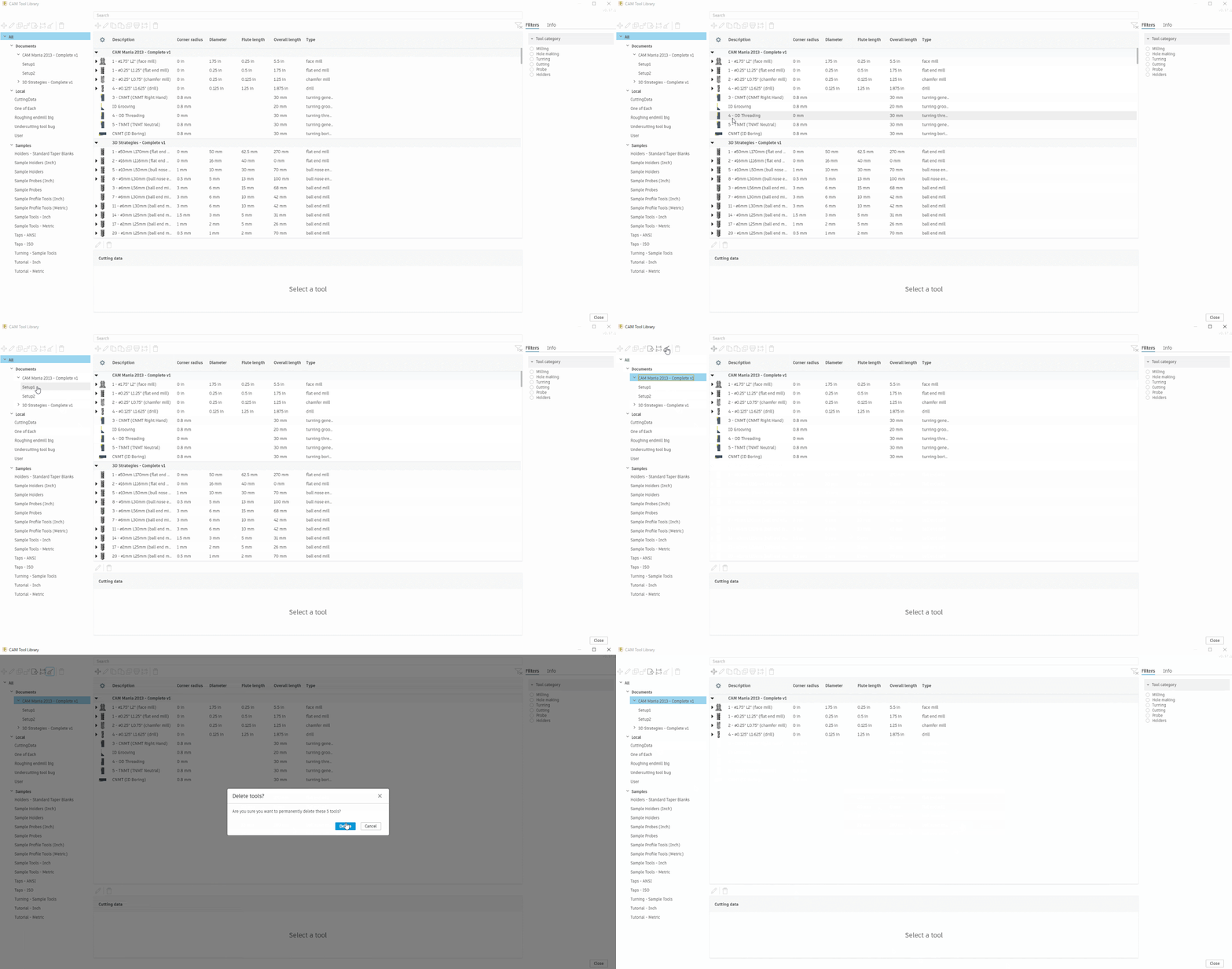
We’ve added the ability to remove all the unused tools from a document. Select the document you’d like to clean up from the tool library tree and then use the Remove unused tools button to remove all the tools in that document that aren’t used in any operations.
We’ve also added the ability to filter tools, as well as a whole bunch of fixes to the tool library preview.
[icon name=”file-text” class=”” unprefixed_class=””] Check out the Tool Library Preview blog post
[icon name=”comment” class=”” unprefixed_class=””] talk to us on the forum
[icon name=”thumbs-up” class=”” unprefixed_class=””] Improved! Live connection to Haas Classic controllers (Extension)
Probing > Actions > Begin Live Measurement
We’ve extended the power of the Surface Inspection strategy by enabling a live connection to the Classic Haas controller for real time results and feedback, allowing for faster decision making. This step forward lays the groundwork for further live data collection and connections to manual measuring devices and CMMs for part inspection. Simply connect your computer to the machine controller using an ethernet cable or serial cable, and navigate to Begin Live Measurement.
[icon name=”file-text” class=”” unprefixed_class=””] See Help Documentation
[icon name=”comment” class=”” unprefixed_class=””] Talk to us about it
[icon name=”wrench” class=”” unprefixed_class=””] [expand title=”Issues Fixed – Click to expand”]
- Tony.richmond.ii noticed that the Select Same Diameter option went missing from drill operations. No, you weren’t going crazy, this was our bad – this option has now been restored.
- The Turning Groove strategy now supports an additional spring pass through the option “Repeat Finishing Pass” even when roughing passes are turned off.
- Fixed an issue with Single Groove operations with pecking enabled where the tool was ignoring the radial stock to leave and machining up to the bottom of the groove.
- Fixed an issue with Profile Roughing toolpaths that were not clearing unfinished material by the expected amount of clearance during rapid traverse moves.
- Fixed an issue with certain Profile Finishing toolpaths that were generating an incorrect path when the compensation type was set to “In control”.
- Fixed an issue with certain Profile Finishing toolpaths that were gouging through the part while retracting after the end of the toolpath.
- Fixed an issue with certain Profile Roughing toolpaths that were incorrectly getting trimmed before the back Z limit.
- Fixed gouging issues with certain Profile Roughing toolpaths.
- Fixed certain Profile Roughing and Finishing toolpaths that were failing to generate.
Tool library fixes
- Delete tool warning – The confirmation dialog that appears when you delete tools will now show you which operations the tools are used in so that you can have confidence you’ve selected the tool you wanted to delete.
- Text legibility – We’ve heard that some customers were finding the text in the tool library difficult to read because of the light colors. We’ve made some changes to make the text darker and clearer.
- Column customizations are now remembered when returning from the edit tool to the main tool library page.
- Performance improvements – We know that you need to work as efficiently as possible, so we’ve made some more performance improvements.
- Tooltip on tools – We heard that some of you were finding the tooltips on tools in the tool list frustrating, so we’ve disabled them.
- Cutting data tab – We’ve moved some of the parameters on the Cutting data tab so that they are displayed in a more logical order.
- Dimension diagrams for S, T, V and W type turning tools are now displayed on the edit tool page.
- Invalid tools – Libraries containing an invalid tool will now show a warning icon in the tool library tree.
[/expand]