
An important product update addressing recent data issues is now available. Please update Fusion 360 ASAP and follow the steps outlined in this Support Article.
May 24, 2021: We pushed a new product update that includes important fixes to the recent data issues where some design documents exhibited missing thumbnails and/or failed to open due to “unresolved components”. If you haven’t updated Fusion 360 yet, we urge you to go through the following 3 steps:
- Save your existing work.
- Restart Fusion 360 to get the latest update.
- After update is successful, follow the steps outlined in the Support Article.
If you are still experiencing the issues described, please contact us using the details provided in the support article.
_____
Since mid-April, we’ve received a few reports from the community regarding an “unresolved component” error message. This means you were not able to open design documents containing externally referenced parts or derived parts, and the design documents themselves were stuck in an “unavailable” state.
We are currently seeing a very small percentage of the community hitting this issue, but due the potential impact on your ability to access your design documents and potential data corruption , we want to make you aware and provide mitigation steps. To help reduce potential data corruption, we advise that you immediately follow the steps outlined in the support article.
Our team is actively working on fixing this issue as quickly as possible, and this effort is our highest priority. We are also conducting a deeper investigation into the root cause of the issue so we can prevent it from happening again in the future. We understand that data access is paramount to you, as it is also paramount to us. We sincerely apologize for the inconvenience this is causing to your work, and we will keep you posted on our progress. Thank you for your support and understanding.
___
April 29, 2021| 2.0.10148
Black Toolbar / Black Canvas Issues Fixed
Some of you have reported that when you launched Fusion 360, you saw a black canvas or black toolbar, which prevented you from going any further. Sorry for this – we got a fix out and this issue should be resolved. Please restart Fusion 360 and get the latest update.
If you tried the work-around that was suggested prior to this fix, it’s best to undo that work-around and remove the environment variable mentioned in the work-around.
Sketching & Modeling
Improved! Thin Extrude now support Chaining selections
Design Workspace > Solid tab > Create Panel > Extrude > Thin Extrude Type
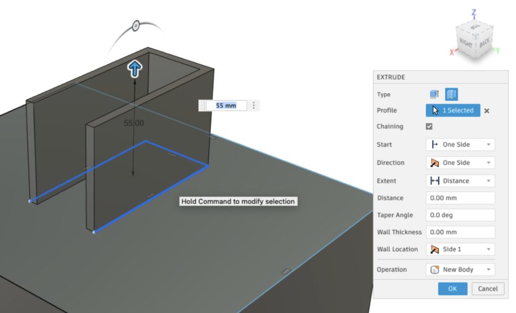
Previously when you picked Thin as an extrude type in the Extrude command and selected an open profile, you were only able to select an entire curve chain, but was unable to select discrete curve segment of a chain. Now when you do a Thin Extrude, you’ll see a Chaining check box (default is on), which will give you the option to turn off chaining, so you can select discreet curves as you see fit.
Simulation Fix:
- bezakdavid told us about an issue where he was not able to run any Spice simulations on his Eagle Schematic. Sorry about that, this is now fixed.
Manufacture Notable Fixes:
- We fixed an issue where re-opening a part that have previously been exported locally incorrectly showed that the toolpaths were out-of-date.
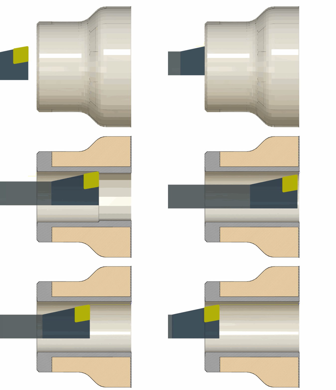
- We found a bug lurking in the Turning roughing toolpath where if you didn’t have Spun Profile enabled, the toolpath gouged into the model and incorrectly machined through the radius. You shouldn’t have to enable Spun Profile to avoid this from happening, so we fixed it and now Turning roughing no longer gouges the model.
- We fixed an issue reported by Farzati.Scott where the tool preview was not showing in the old tool library when you reverted back to it from the new one.
- We also fixed an issue with certain turning profile roughing toolpaths where the tool was starting inside the stock. Now the toolpath starts at the correct Z coordinate (stock front + z clearance).
- There was a problem with certain turning profile finishing toolpaths where they were not generating when the Z stock width was smaller than the tool nose radius. Now the correct toolpath should generate just fine.
Usability
Improved! Properties dialog

Now when you right-click on a component in the browser and select Properties, you’ll not only notice that it now has a modern user interface, but you can also pick different component in the browser and display properties of the selected component without closing the dialog.
This update sets us up to deliver a more cohesive experience around the upcoming Manage Extension mentioned below. If a component is managed through the Manage extension, its info will be displayed in this section, and will also be synced via Fusion Team.
*Coming Soon*
Here are a few projects in flight that are almost ready to land!
See your designs in augmented reality
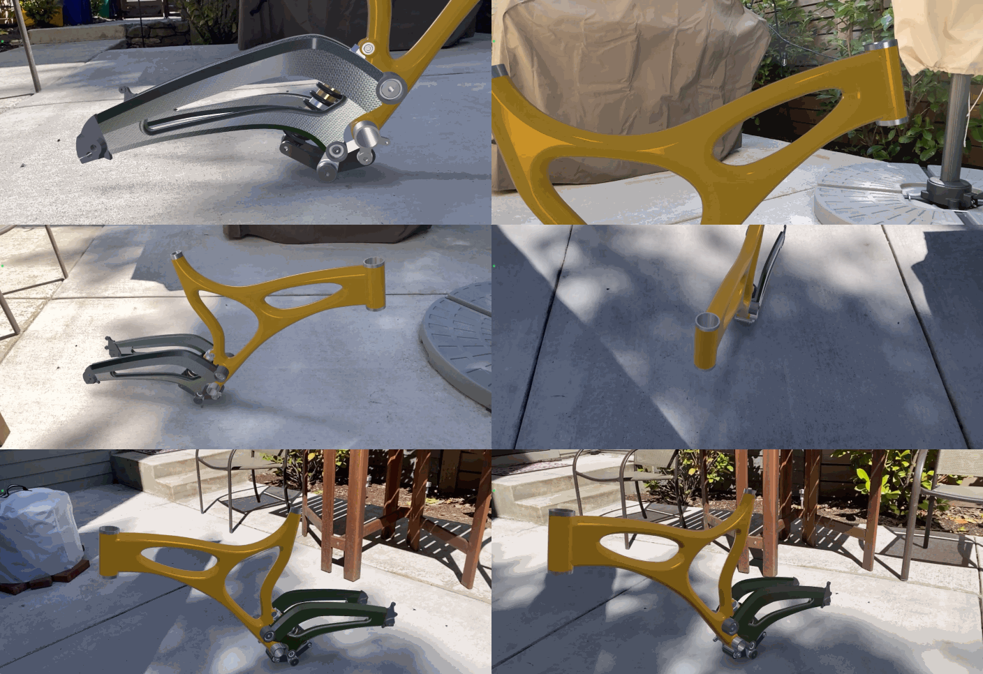
Yup, you read that right. Some of you have been asking for a more interactive, life-scale experience that enables you to visualize and communicate your designs in your own real-life surroundings. We’re excited to give you a sneak peek of what we’re doing around augmented reality. We’re working on enabling you to view your Fusion 360 designs in augmented reality (and to scale) via your iOS devices (or any device capable of reading USDz files). Keep your eyes peeled on the upcoming product updates!
Formlabs SLA support
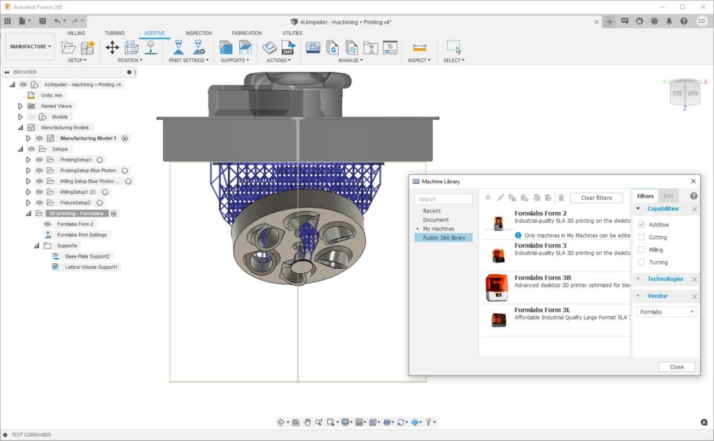
Sometimes, you just can’t get the level of detail and precision that stereolithography (SLA) delivers with Fused Filament Fabrication. If you’re using Formlabs printers, you’ll be happy to know that SLA support for Formlabs printers is coming to Fusion 360. Soon you’ll be able to easily define printing orientation, support structures, and print specs right within the Fusion 360 Additive space. Since your designs are parametric, any changes you make to you model will result in an update to all manufacturing models as well. Prints setups can be updated with a click of a button.
The Fusion 360 Manage Extension
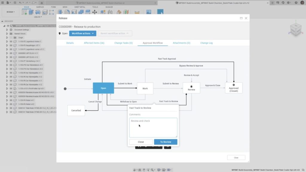
We mentioned this in our Year-in-Review/Roadmap update post at the beginning of the year, and we’re excited to update you that it’s almost ready for prime time. The Manage Extension is designed for teams working on a larger organization. As the scale and scope of engineering projects increases, so does the complexity of data management. Managing engineering changes, release states, and item numbers using manual processes can lead to costly mistakes. With the Fusion 360 Manage Extension, you can unlock additional capabilities in Fusion 360 to help solve these common data management challenges.
To learn more, check out our Fusion 360 Manage Extension website.
___
April 12, 2021 | 2.0.10032
We released a minor update that fixes the following issues found in the Manufacture workspace:
- Shift + tab not working – now it does.
- Operations not generating due to “Turn” and “Tilt” parameters – now they do.
- Fusion 360 crashes when simulating the newly created Probe geometry operation – now it no longer crashes.
___
April 5, 2021 | V.2.0.10027
Usability
New! Insert TraceParts
Design Workspace > Insert Panel > Insert TraceParts Supplier Components
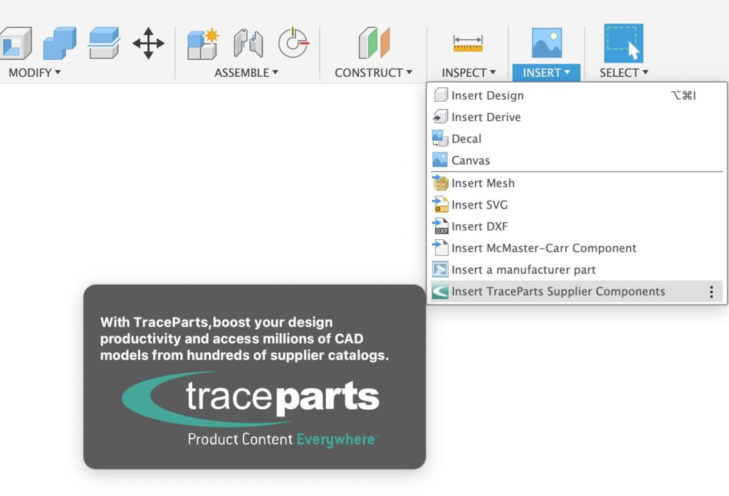
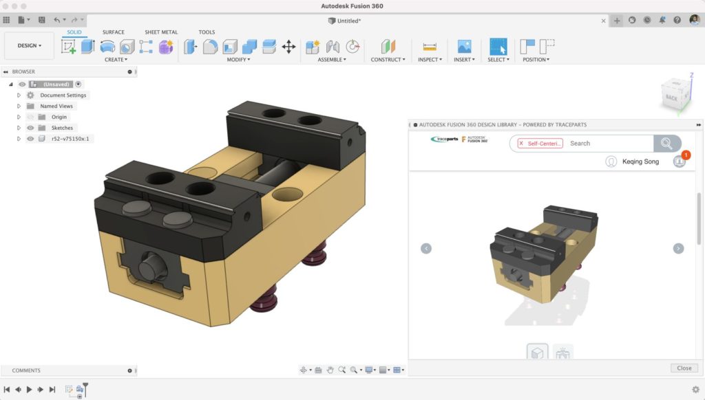
We partnered up with TraceParts to give you access to millions of supplier components, 3d models, CAD files, and 2D drawings right from the Insert drop-down menu. Simply navigate to what you are looking for, sign-in with your TraceParts account, download and voila, you’ve inserted a supplier component directly into your Fusion 360 canvas.
New! Send to Fusion 360 from Inventor 2022
If you’re using Inventor, you can now extend your Inventor workflow by sending your part directly into Fusion 360 with a click of a button. This is made possible via a Fusion Team connection. Check out the what’s new video above to see it in action.
Improved! UI framework
We recently updated our UI engine, which contains a number of behind-the-scenes updates to Fusion’s UI framework and modeling components. Some of the usability issues you’ve been experiencing with Fusion 360 have been addressed in a few updates back, but some may be addressed in this one. Let us know if you’re seeing wonkiness in the UI so we can capture it on our backlog. We’d also appreciate it if you do a quick search for your issue before posting it to our forums or the comment section; chances are someone has already reported it.
Sketching & Modeling
New! Create a Full Round Fillet
Design Workspace > Modify > Fillet > Type > Full Round Fillet
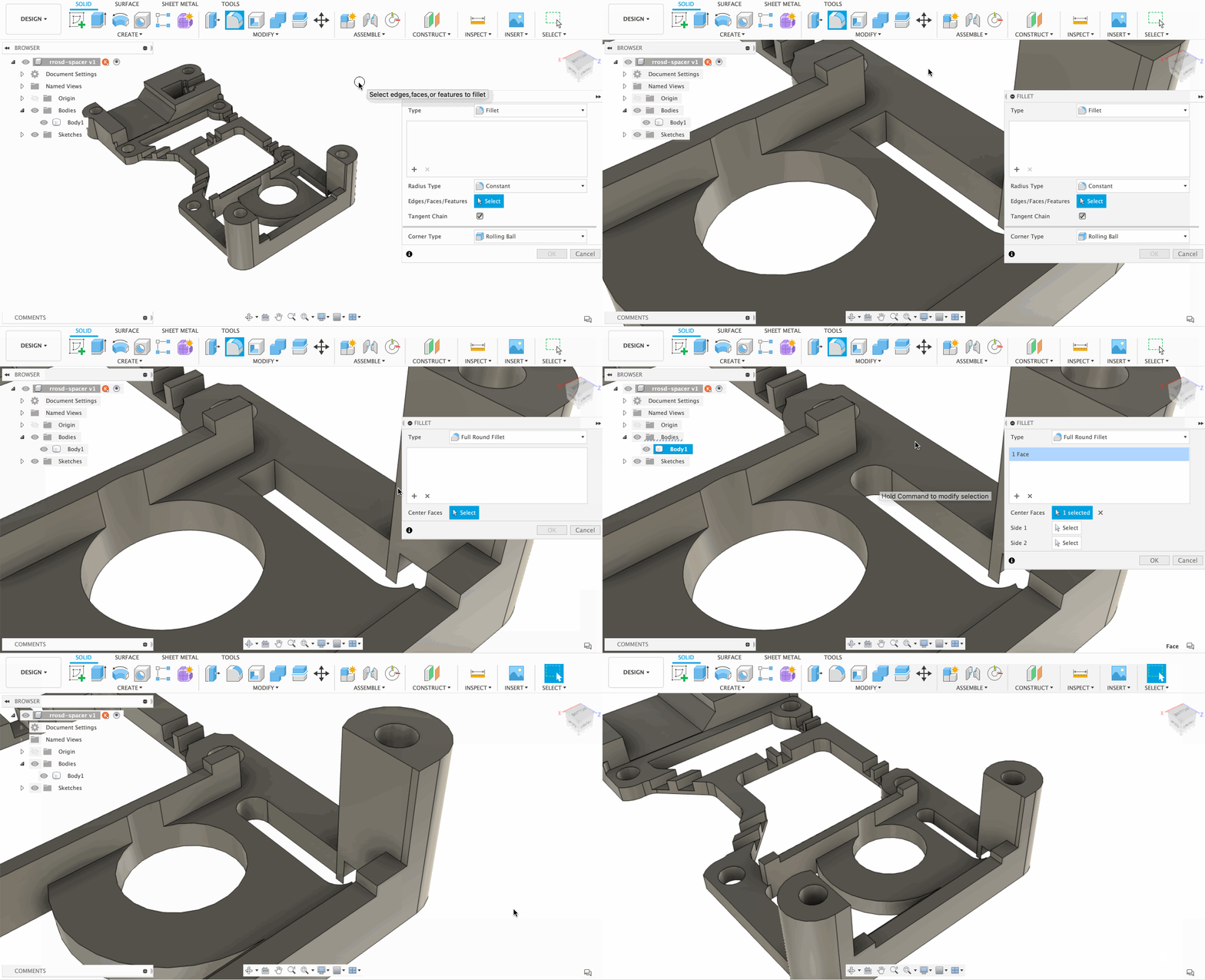
Previously if you wanted to create a full round fillet, you’d have to select 2 edges and go by trial-and-error to get the closest result. Now within the Fillet tool, there is a new Fillet type called Full Round Fillet, that does exactly what you think it does. No more guessing around – select a face and the tool will automatically find the 2 opposite edges and create a full round fillet.
– Learn how to create Full Round Fillets.
– Learn about Center Face Selection examples for Fillets
– Check out Product Design Online’s Full Round Fillet tutorial
Improved! Thin Extrude now supports Open Profiles
Design Workspace > Create > Extrude > Type > Thin Extrude
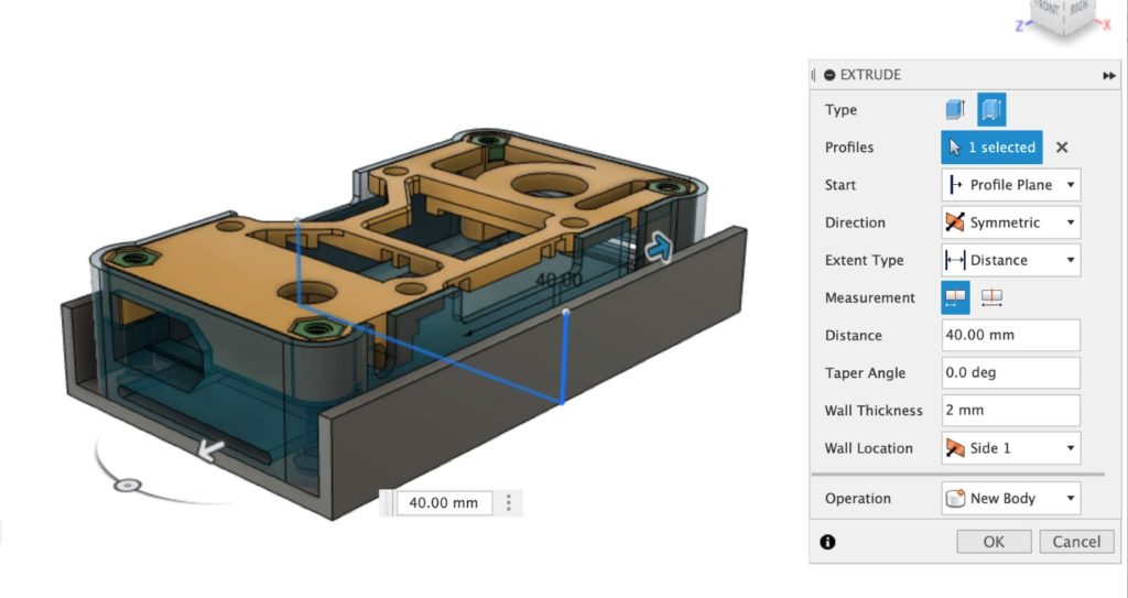
A couple updates ago, we introduced the ability to Thin Extrude within the Extrude tool. You were able to Thin Extrude sketch profiles that were closed. In this product update, we’ve improved on this Extrude type to support open sketch profiles. This should give you even more flexibility while using the Extrude tool.
– Learn how to use Thin Extrude on an open profile
Improved! Text curves are now smoother after Explode Text
Right-click on Sketch Text > Explode Text

Depending on the font you’re working with, it’s sometimes necessary to “explode” the text. Explode Text converts your text into usable sketch geometry, and previously some edges on fonts that contain lots of curves were not very smooth. We improved the performance of Explode Text and now text curves are a lot smoother after the text has been exploded.
Improved! Font dropdown now shows preview of font
Design Workspace > Create Sketch > Text > Font
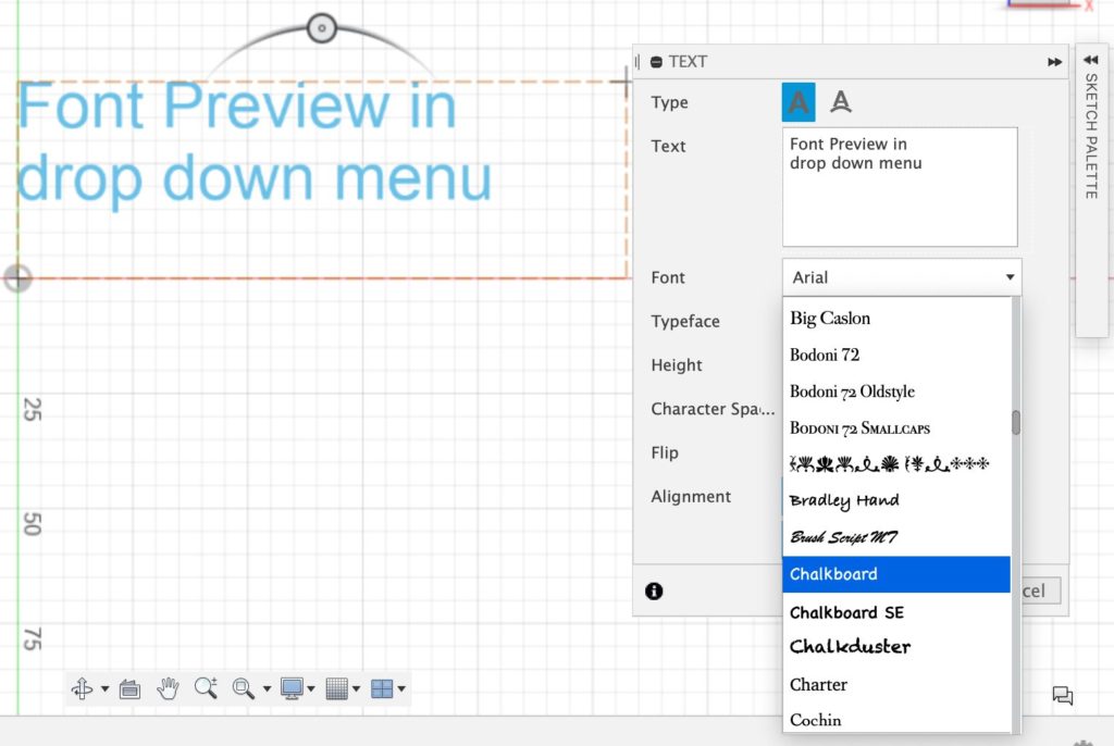
Now when you’re looking through your font library in Sketch Text, you’ll notice that each font will show a preview of what it looks like, right within the drop-down menu. This should help you scan the list of fonts and zero in on the one that you want to use faster.
Electronics
New! Connectors and battery holder added to content libraries
File > New Electronics Design > New Schematic > Add part
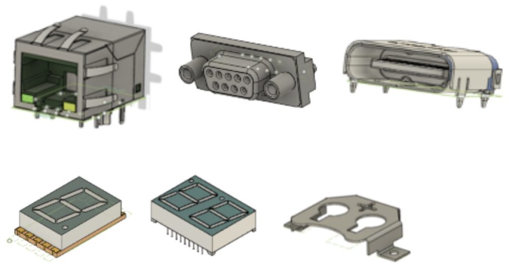
Connectors are an essential part of all PCB designs. Every time you charge your tablet, your phone, or plug your computer into the internet cable, you interact with them daily. Our developers have expanded the content to include many of these connectors, such as RJ type connectors, D-Subs, and USB connectors. We have also added LED segment displays which are great when your design needs a read-out display and coin-style battery holders.
Generative Design
Improved! Access to Start 7-day Generative Design Extension Trial
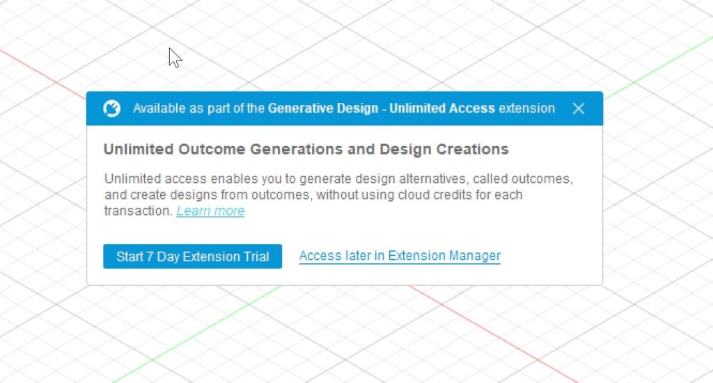
The 7-day Generative Design extension trial is one of the best ways to get started experiencing all that Generative Design has to offer. We wanted to make it extremely easy for users to start the trial, so now upon entering the workspace, you will be greeted with a prompt to start the trial if you meet the eligibility criteria, i.e., you haven’t already run the trial or subscribed to the Generative Design extension. You can always get access to the Generative Design extension through the Extension Manager, as well.
– Learn more about Generative Design – Unlimited Access extension.
Improved! Moment Command
Design Conditions > Structural Loads >Moment
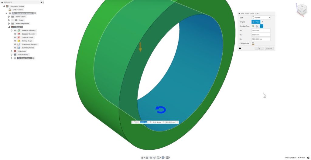
We are continuing to extend consistency across the Generative Design and Simulation workspaces. The Moment command will now allow you to define moment directions that are not parallel to the axis of the cylinder. In the example here, you can see we have applied a moment to a cylindrical face but defined the axis of rotation for the moment about the vertical axis in the design. This will give you additional ease of use in defining the loads your generative design will experience.
– Learn more about Moment load in a generative study.
Drawings
New! Break View now available
Drawings > Create > Break View
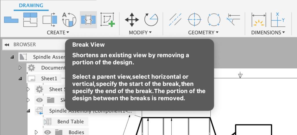
Good news! The Break View tool is the Drawings environment is now out-of-preview and available in the drawing environment.
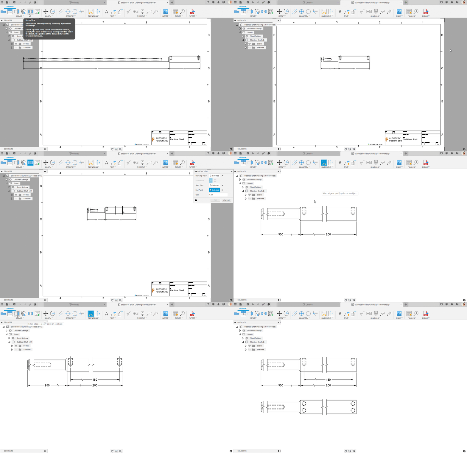
A broken or break view reduces the size of long models by removing irrelevant portions, to make it fit the drawing sheet. Dimensions that span the break show the true length.
Improved! Create Smart Templates with All Level assemblies
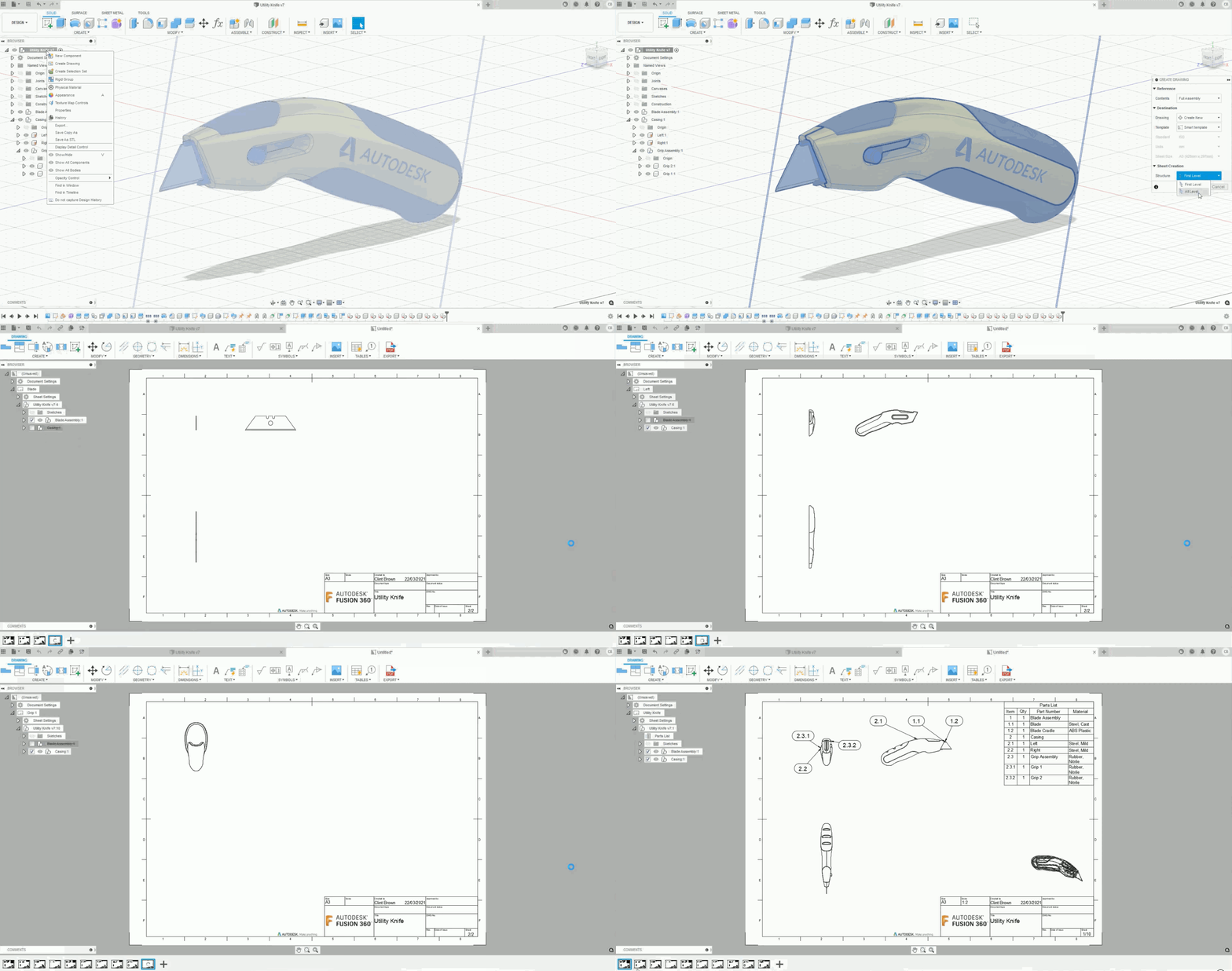
Workspace Switcher > Drawing > Create > Sheet Creation > Structure > All Level
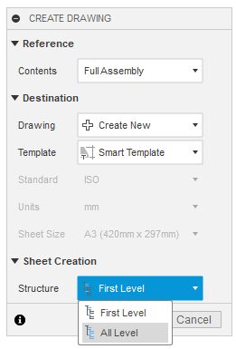
Smart templates now support “All Level” assemblies, which makes drawing creation even faster than before. The handy video below, shows the difference between “First Level” & “All Level” sheet creation.
Improved! Toolbar Usability
Workspace Switcher > Drawing > From Design or From Animation

The toolbar in the drawing environment has been given a subtle update. This includes better grouping of commands, new icons and better tooltips. The user experience team leaned heavily on user research to inform the new design, as a result, commands are now more discoverable and are grouped more logically.
Manufacture
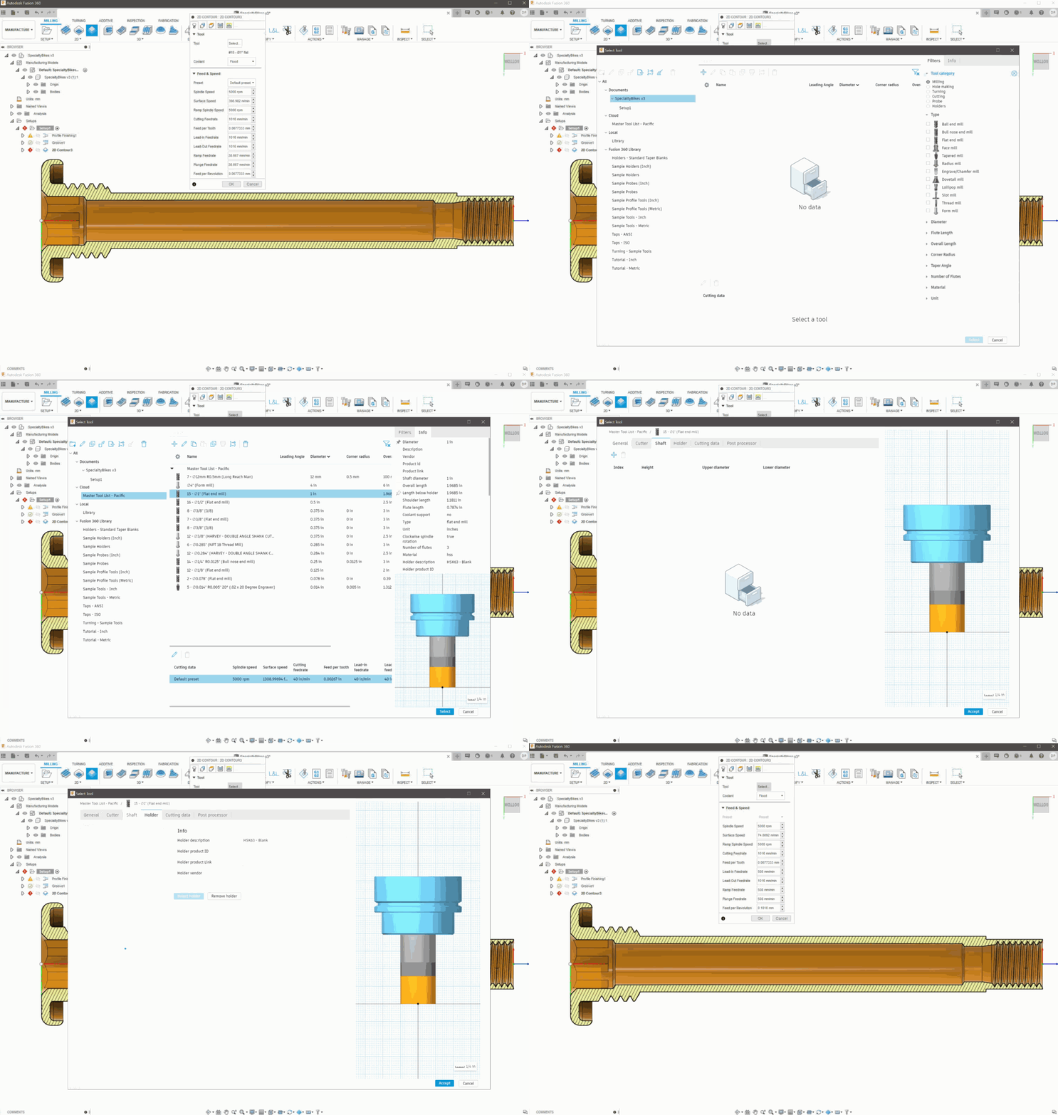
Improved! Toolpath Simulation Usability & Performance
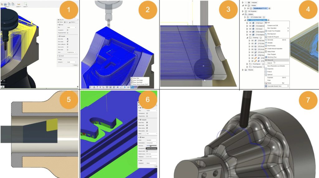
We’ve added more flexibility around how you can show or hide tools and toolpaths:
- Show/Hide leads and links in Simulation
- Show/Hide tool, shaft, holder – out of simulation
- Display the tool on the cursor
- Show/Hide multiple toolpaths
- Section View Stock in Simulation
- Simulation Accuracy Slider
- Follow Tool option
[expand title=”Learn more about each improvement“]
Show/Hide leads and links inside of Simulation
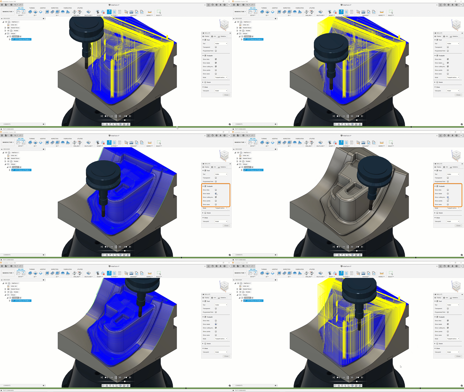
You can now show and hide the leads and links when they obscure the areas of interest.
Show/Hide tool, shaft, holder – outside of simulation
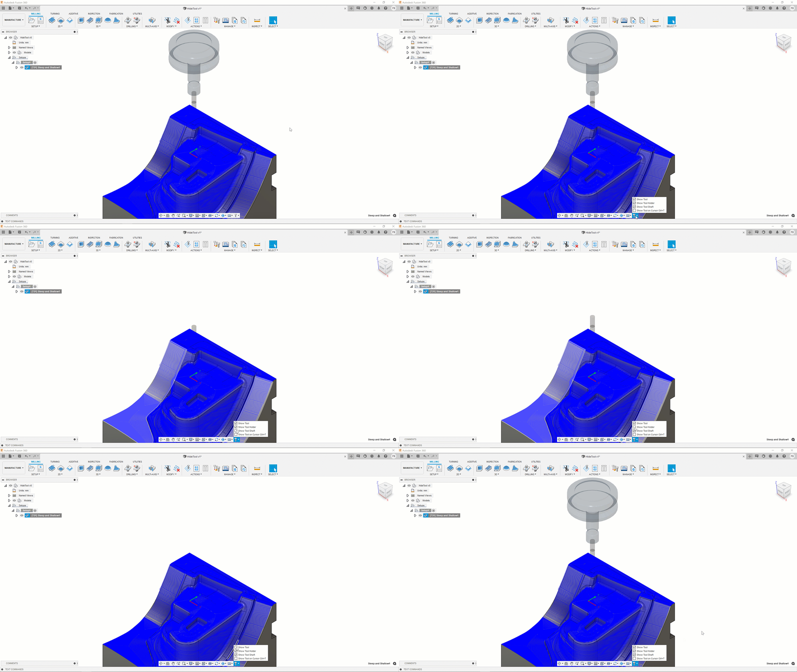
If the tool, shaft, or tool holder is blocking your view, you can also hide them to clearly see specific areas of the toolpath.
– Learn how to control the tool’s visibility.
Display the tool on the cursor (CTRL+T)
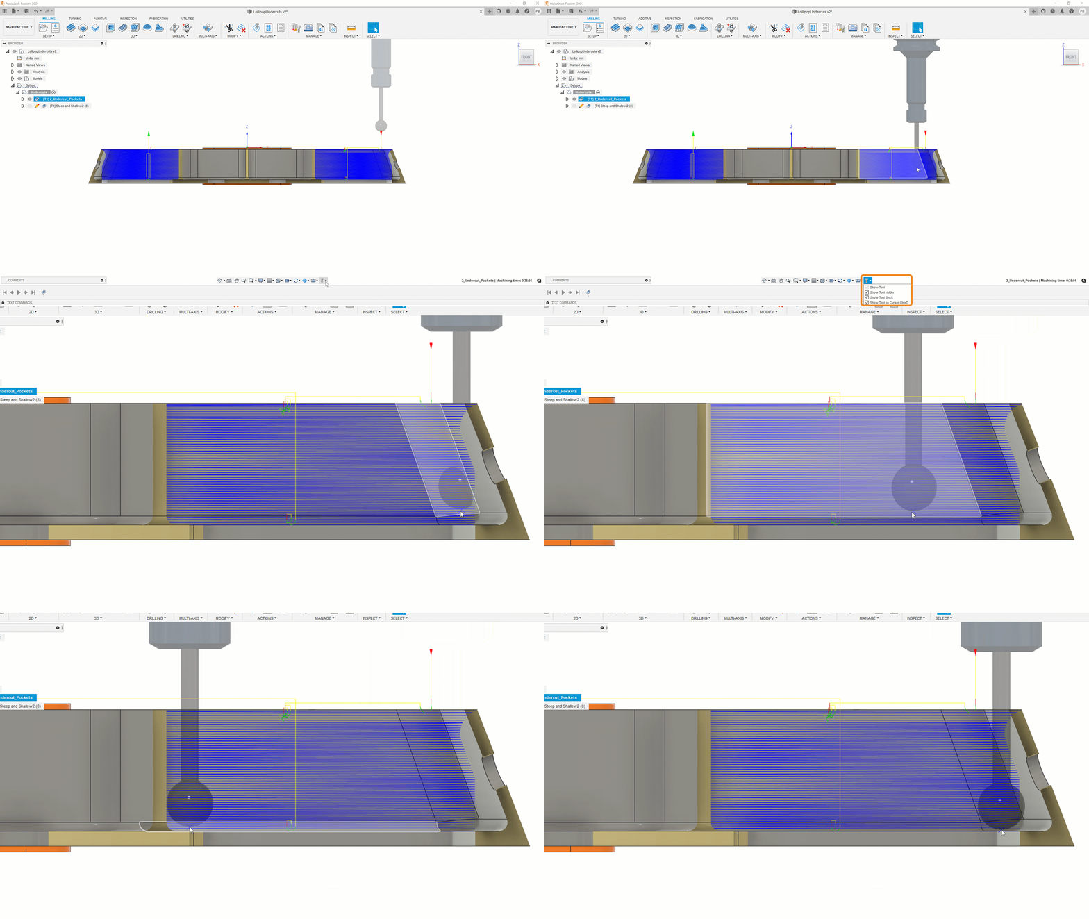
The last option in Show/Hide Tool is Show Tool on Cursor, will enables a preview of the tool right at your cursor, aligned to the tool orientation so you can see exactly where it is and where you want to put it.
– Learn how to see a preview of the tool on the cursor.
Show/Hide multiple toolpaths
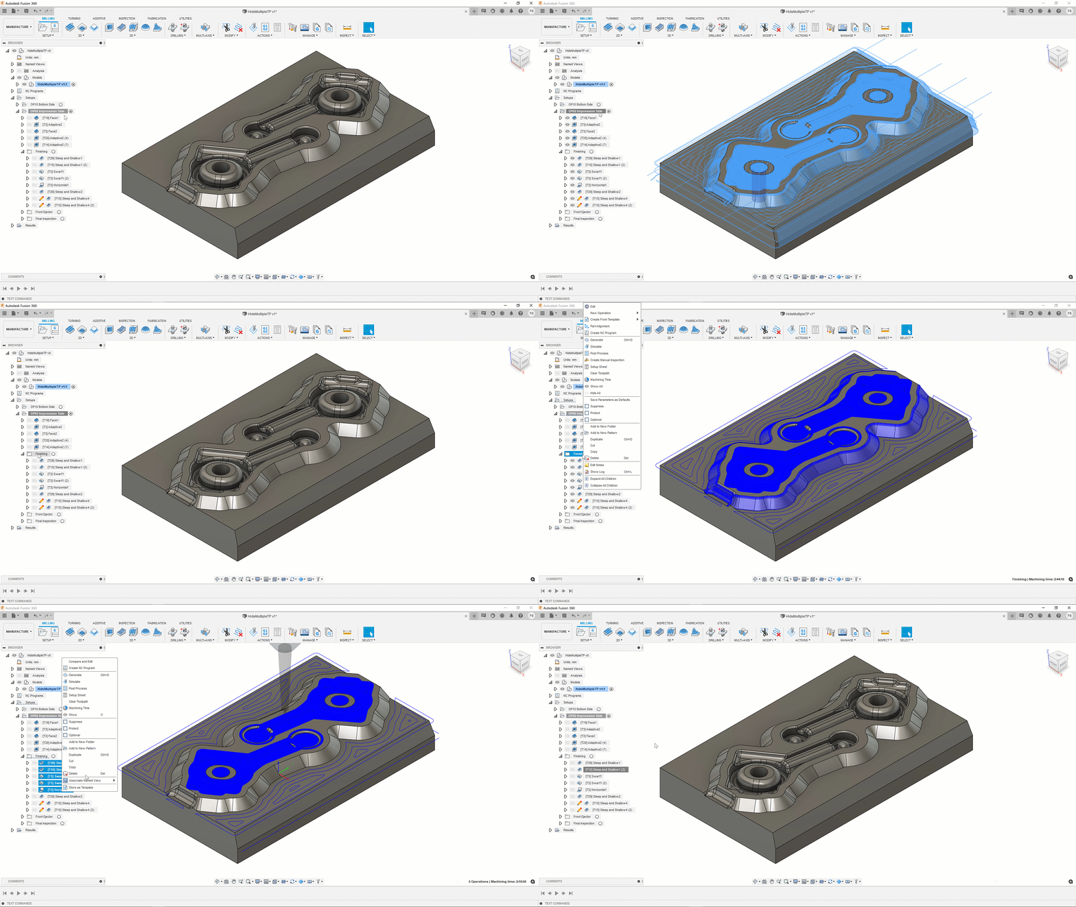
Similar to the Design workspace, you can now show and hide multiple toolpaths. The right-click menu from the browser now includes the option to Show and Hide. You can also use the V keyboard shortcut to toggle Show and Hide.
– Learn how to control a toolpath’s visibility.
Section View Stock in Simulation
Now when you simulation your toolpath, you’ll also be able turn on Section View and see the Stock section.
Simulation Accuracy Slider
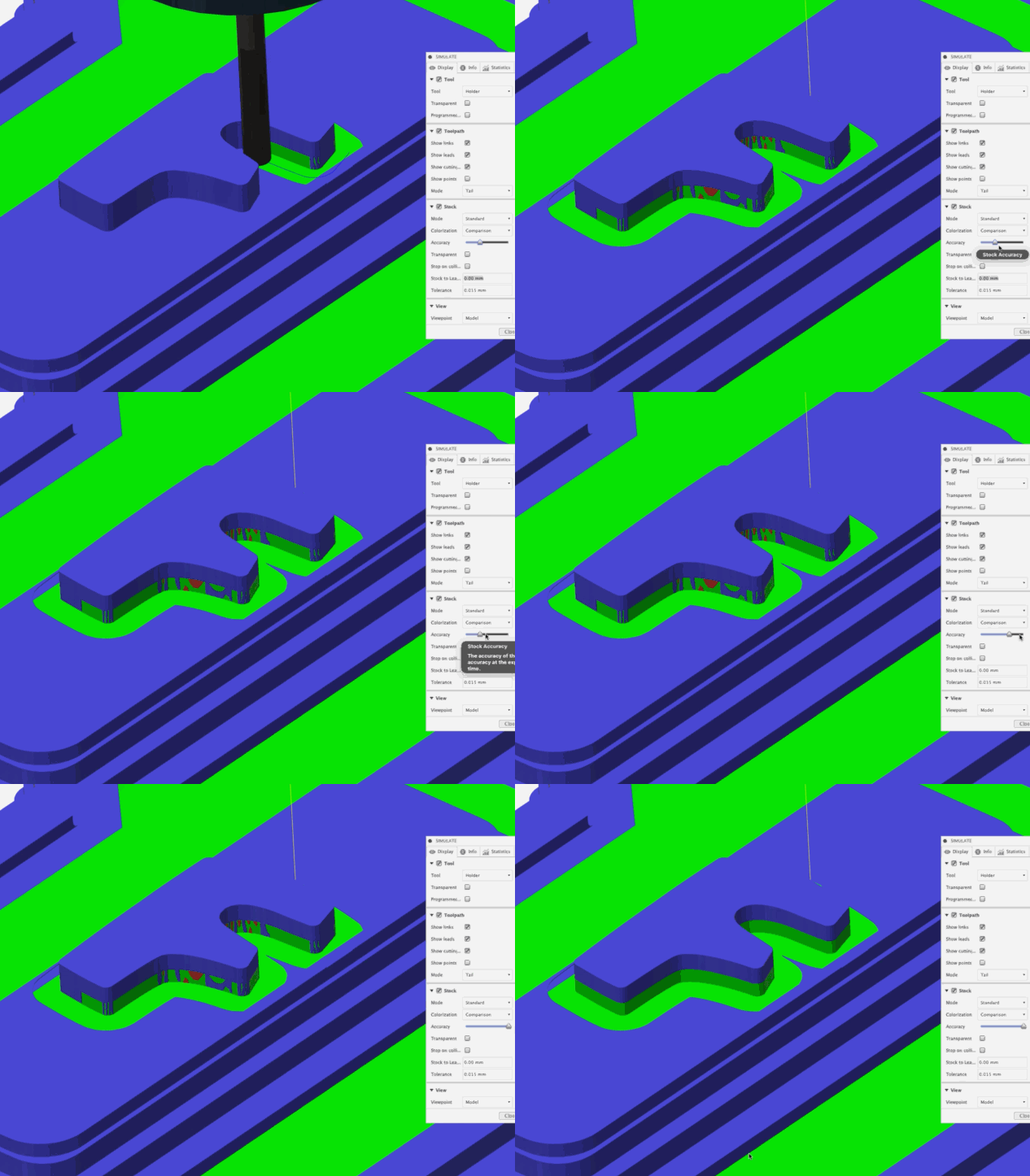
There is also a new Accuracy slider that will enable you to adjust the simulation quality.
– Learn how to simulate manufacturing operations.
Follow Tool option
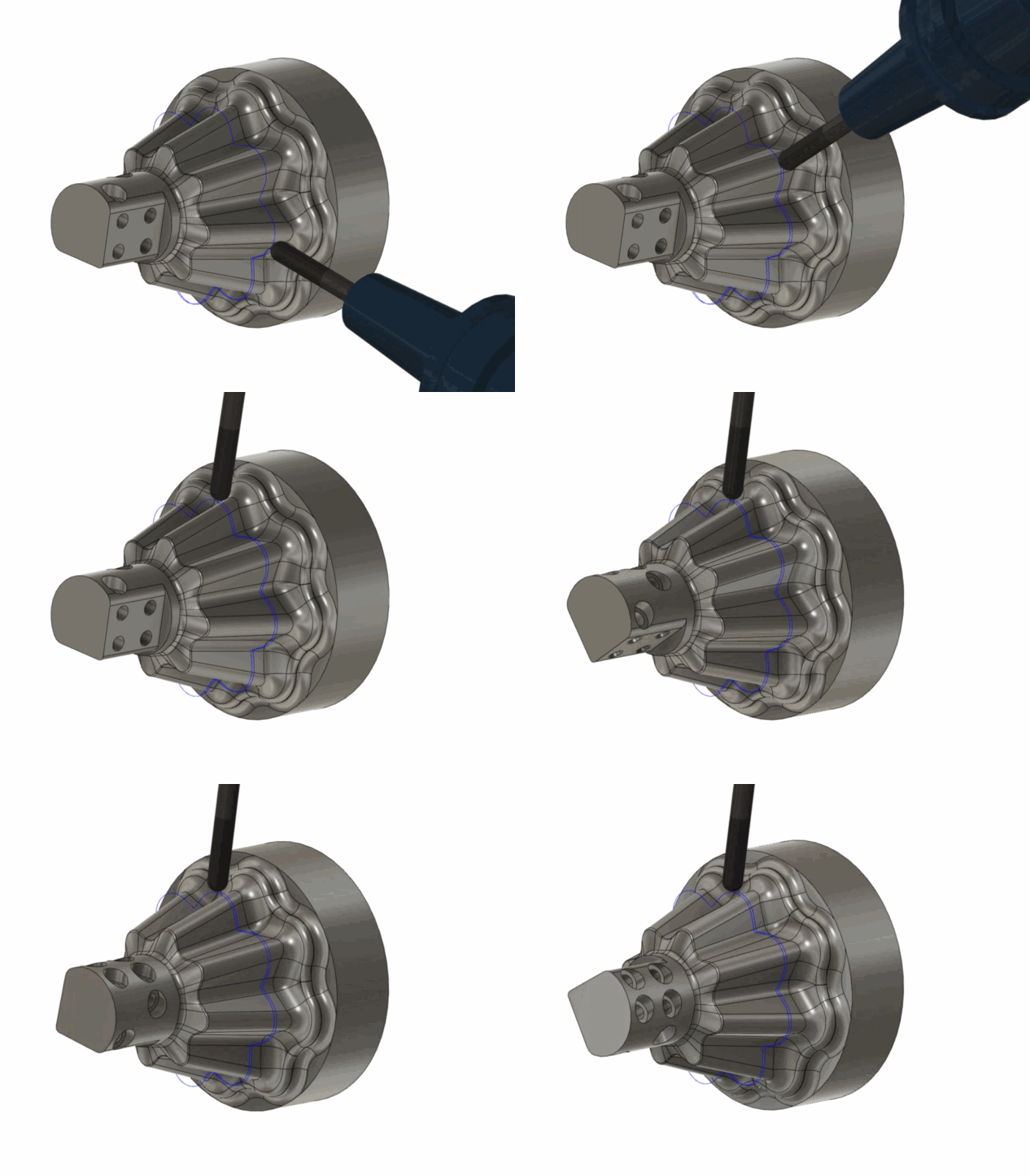
Instead of having a still view of the part being cut, you can now choose to view the simulation by following the tool, and see the part move from the POV of the tool itself.
– Learn how to change the viewpoint during simulation.
[/expand]
___
Improved! Defaults, Displays, Auto-completes, Tooltips
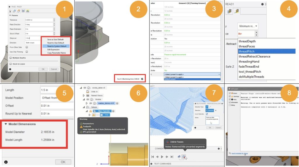
Here are some areas where you’ll see better information and general improvement in usability:
- Renamed make/reset default options
- Display Machining Time
- Compare & Edit
- Better Autocomplete
- Display Model Dimensions
Icons for errors, valid, and valid with IPS(still in development)- Show notes in timeline tooltip
- Better error reporting
[expand title=”Learn more about each improvement”]
Renamed make/reset default options
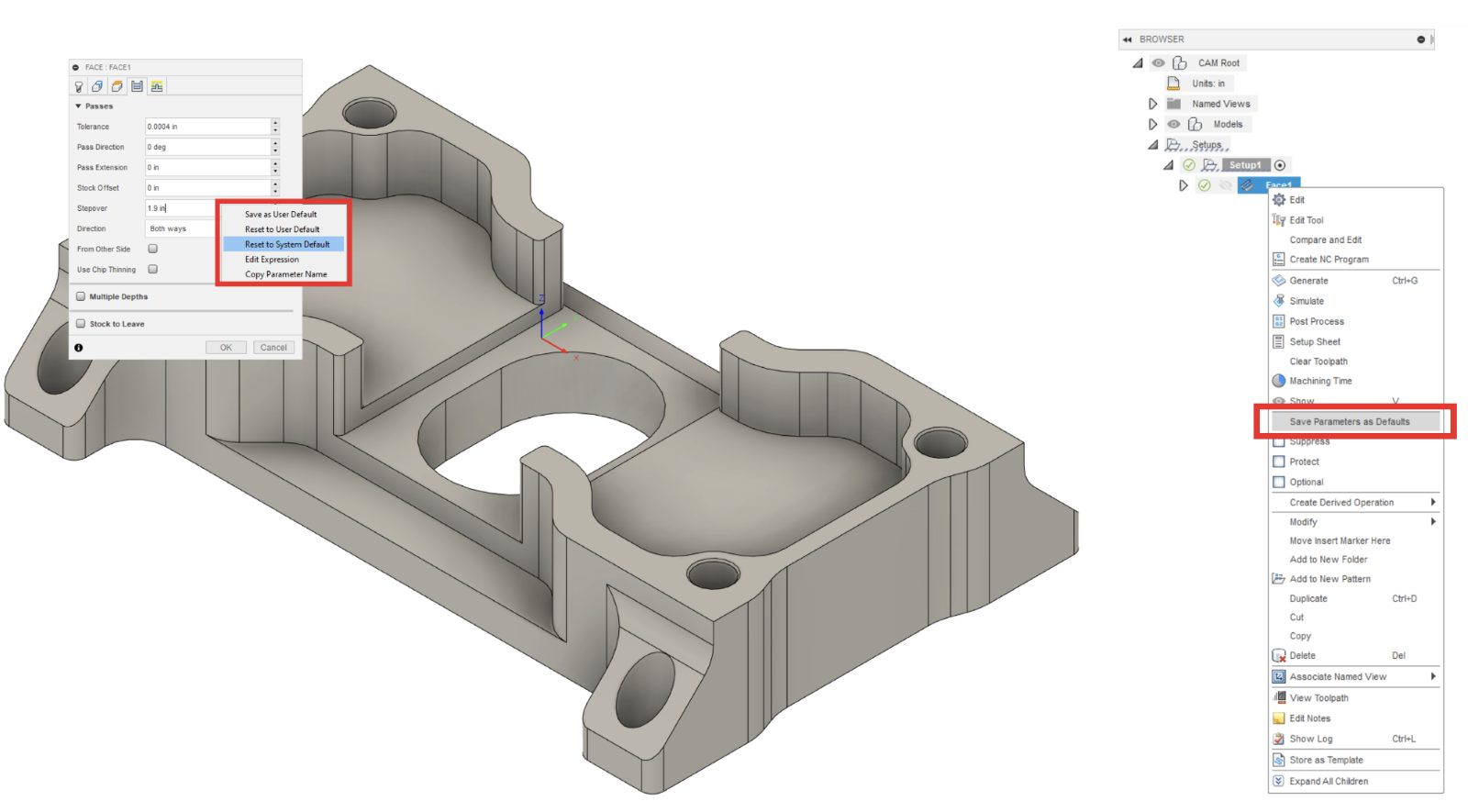
Now when you right-click on a value entry field, you’ll see the options to Save as User Default, Reset to User Default, and Reset to System Default.
Display Machining Time

Machining Time is now displayed in the bottom right corner, decluttering the browser.
– Learn how to view the machining time for operations.
Compare & Edit
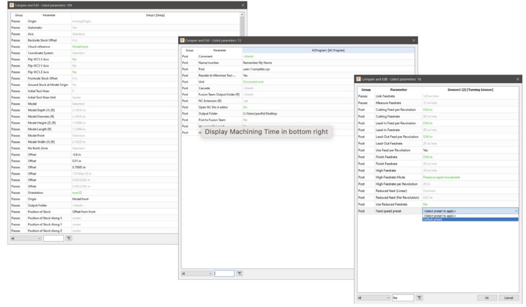
You can now also Compare and Edit Setups, NC Programs, and Cutting Presets side-by-side.
Better Autocomplete
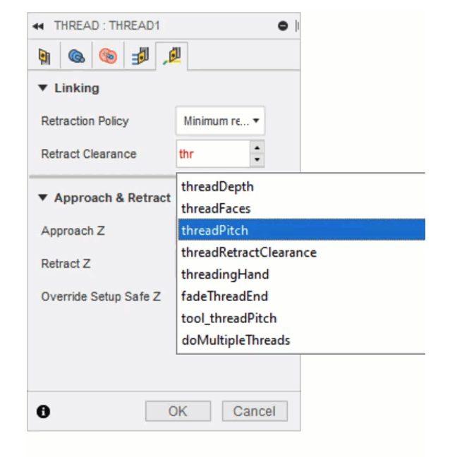
Start typing in a field such as Retract Clearance and Autocomplete will help you narrow down your choices as you type more letters.
Display Model Dimensions

Previously known as Stock Dimensions, Model Dimensions are now directly shown within the Setup dialog.
Icons for errors, valid, and valid with IPS (Coming Soon)
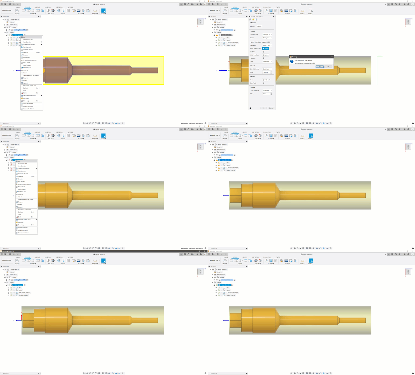
We also improved the icons for errors, warnings, valid, and valid with IPS, just enough to clearly distinguish them at-a-glance without being distracting.
Show Notes for individual toolpath modifications in timeline tooltip
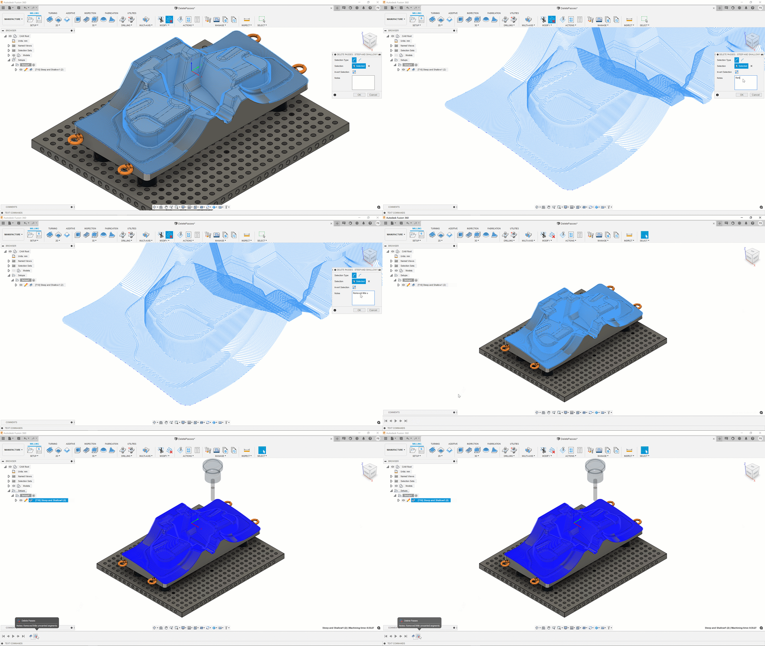
Adding notes to a toolpath modification (such as Trim or Delete Passes) can help you better organize what you’ve changed and why you’ve changed it. Now when you hover over the entity in the timeline, you’ll also see the notes you’ve added to the toolpath.
– Learn how to trim a toolpath.
– Learn how to delete passes or segments of a toolpath.
Better Error Reporting

When you click on the Warning icon next to your toolpath, you’ll notice better error reporting in terms of what you need to know, as well as a link at the bottom that takes you directly to a page that has pre-populated search results related to the issues mentioned in the warning dialog.
[/expand]
___
Improved! Probing Usability
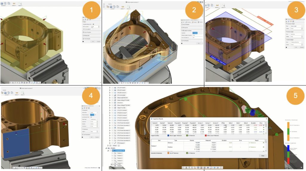
Here are 5 new improvements we’ve made to the Probe tool:
- Better guidance in updating work offsets
- Better toolpath selection for Probe Geometry
- Drag “bottom height” for more consistent probe positioning controls
- Drag probe position on “Surface at Angle” selections
- Combine Inspect Surface & Probe Geometry results for the same part in the same folder
[expand title=”Learn more about each improvement”]
Better guidance in updating work offsets in Probing
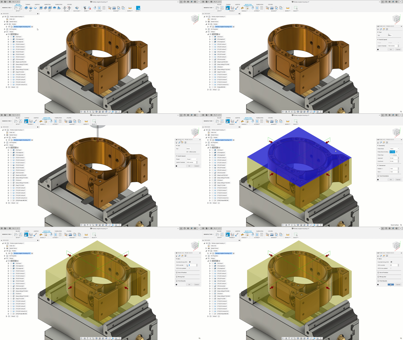
A setting called ‘Override Driving WCS’ allows you to use two different work offsets but the User Interface did not explain which was which or how it works. We have made changes to the interface and improved the tool tips with a better, more task-oriented description. A new label of ‘WCS to be updated’ shows explicitly which work offset will be adjusted and the explanations are much clearer.
– Learn about Probe WCS
Toolpath selection for Probe Geometry
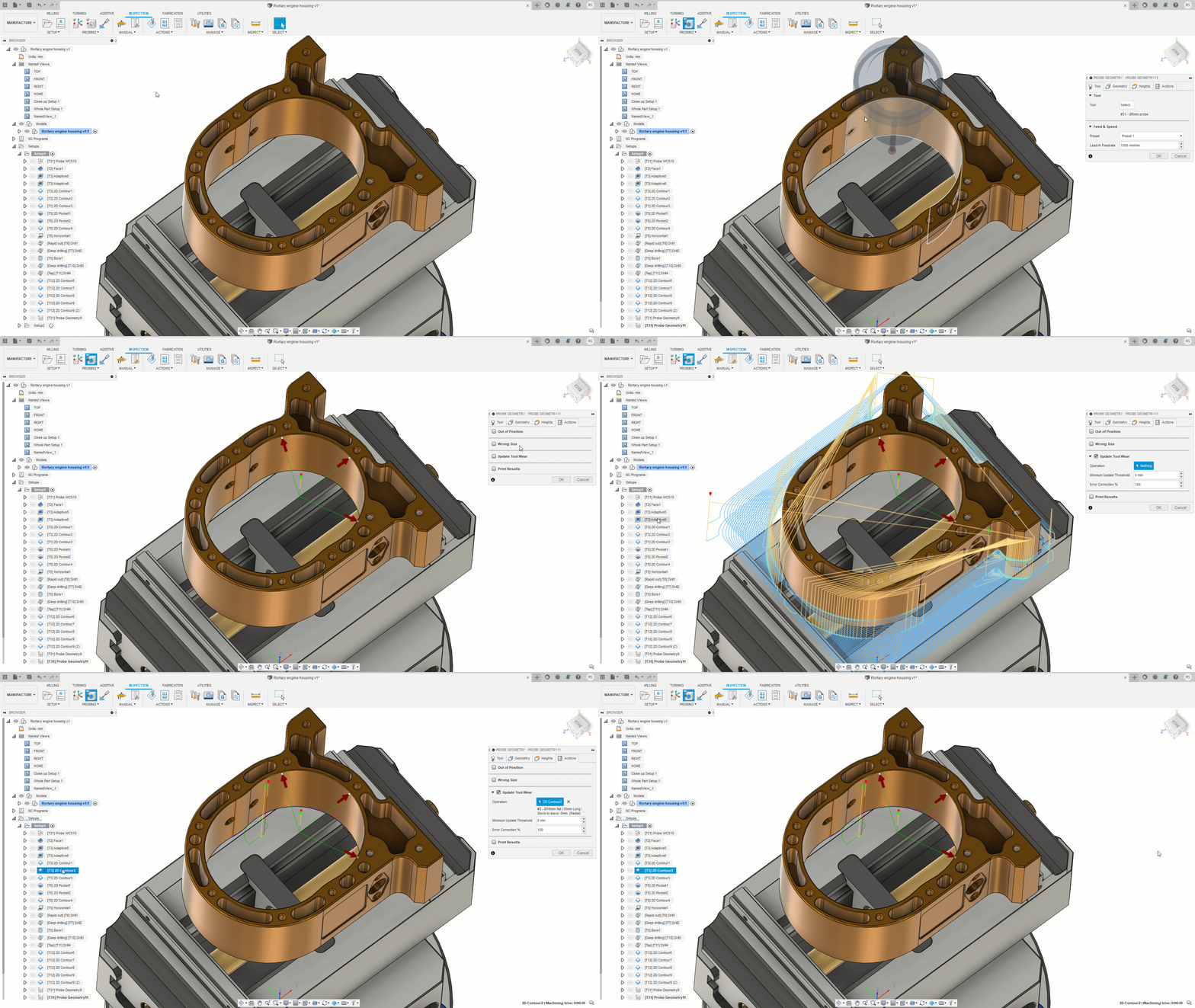
Previously you selected the toolpath just by picking from a list, but if you had lots of toolpaths with similar names it was hard to tell which was which. Now when you hover the mouse over a probe path, you now see a preview. This helps you to identify the correct toolpath more quickly and clearly.
– Learn about Probe Geometry
Drag “bottom height” for more consistent probe positioning controls
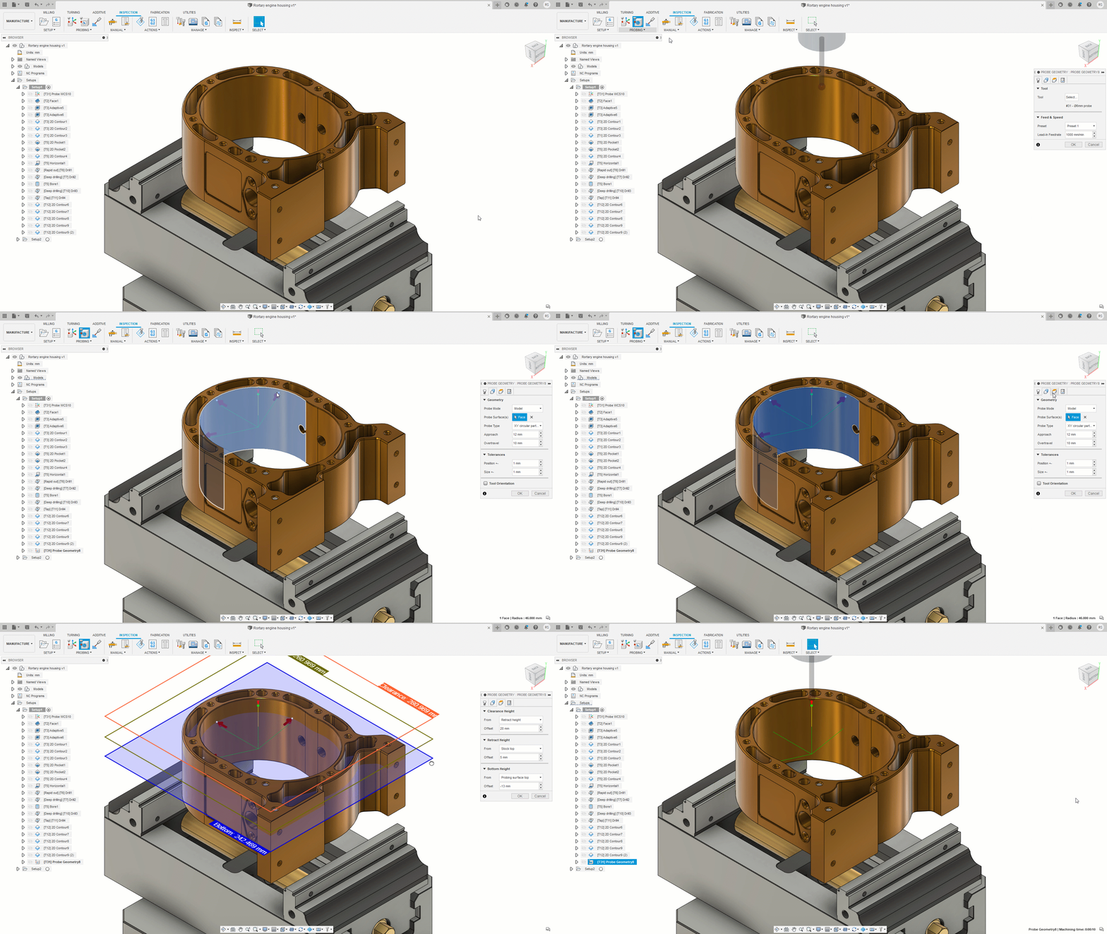
The Probe WCS and Probe Geometry already use the draggable arrow controls so that you can adjust the position from side-to-side just by dragging the point at the tip of the arrow. Now you can also adjust the probing height by dragging the bottom plane. This makes the overall experience more consistent.
– Learn about Probe WCS and Probe Geometry
Drag probe position on “Surface at Angle” selections
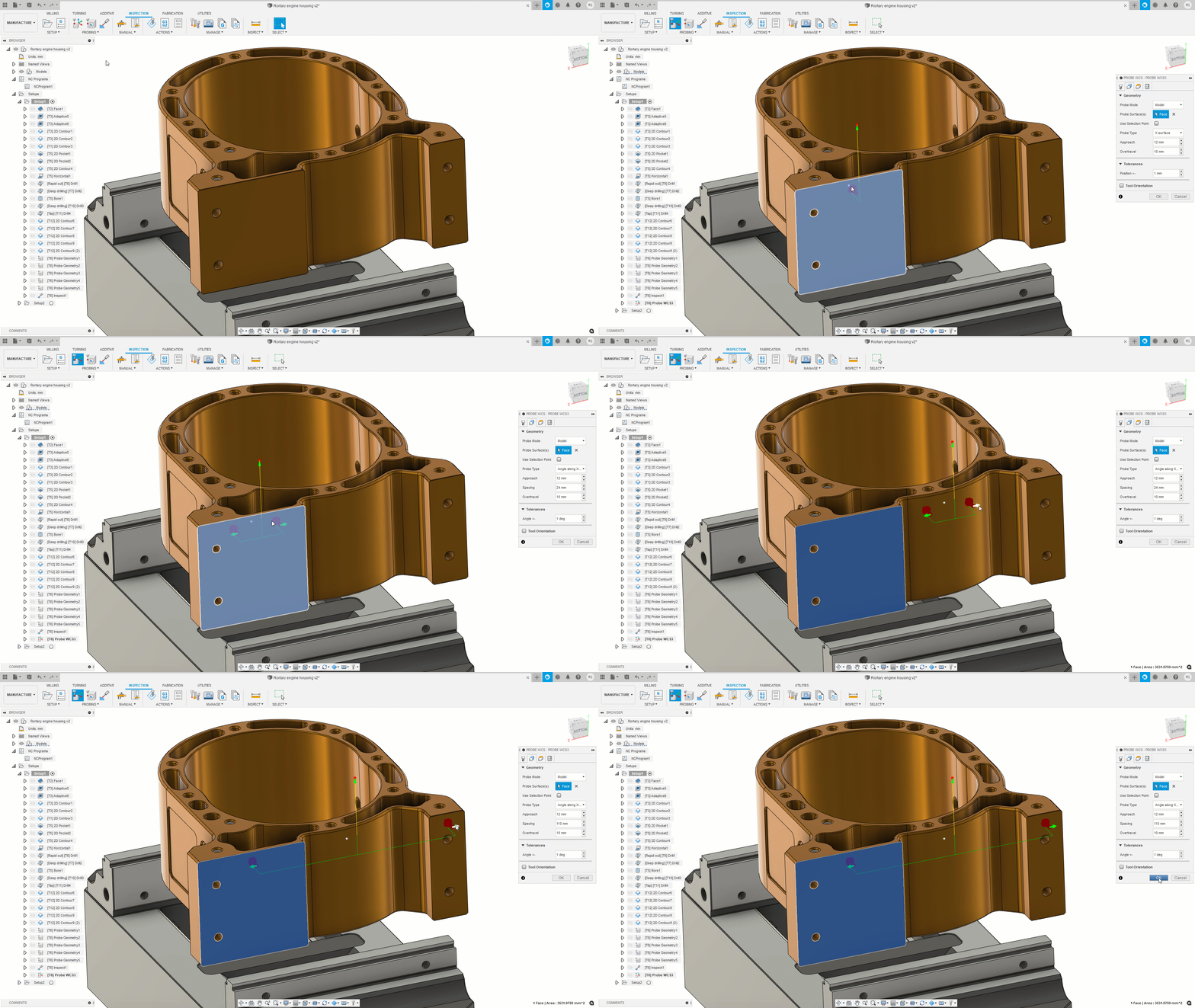
Previously, it would have been very difficult to position points either side of a wide gap like this. You would probably have had to create a fill-in surface to position the center point before typing the numbers to space the points. Now you can select one of the sides, move the center position by dragging the center point, and spread the points by dragging a new arrow. It’s much quicker and easier, and we think it’s more intuitive too.
Combine Inspect Surface & Probe Geometry results for the same part in the same folder

Results were arranged in folders grouped by probing type. This made it easy to identify the different types of results but harder to group all the results for the same part. The import now creates a folder for the part and arranges the different types of results in sub-folders. It is now much easier to identify all the results for a particular part and create the inspection report.
– Learn about inspection results
[/expand]
___
Improved! Turning Toolpath Usability
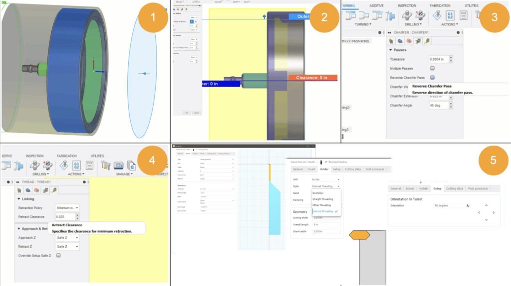
- Safe Z & Chuck Drag Handles
- Spun profile Visible in all Tabs
- Reverse Direction Chamfer Option
- Minimum Retract for threading
- Turning options in the Tool Library
[expand title=”Learn more about each improvement”]
Safe Z & Chuck Drag Handles
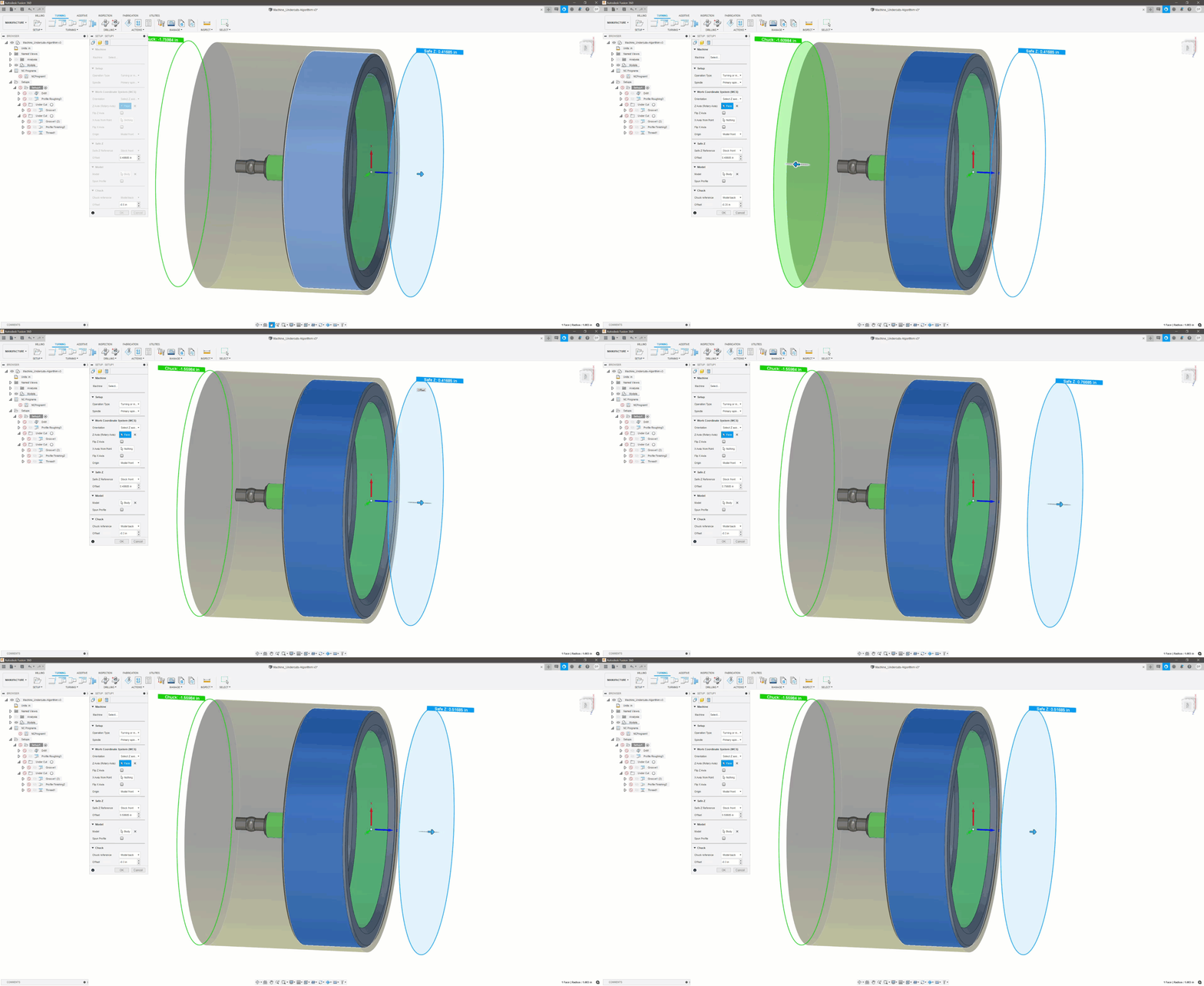
You can now drag the arrow manipulators to modify your Safe Z and Chuck distances.
Spun Profile Visible in All Tabs
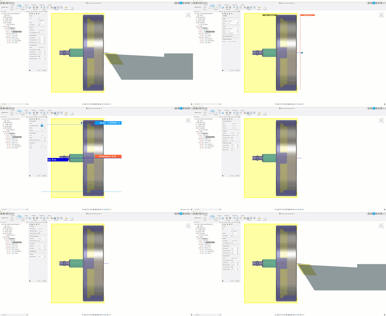
This option displays the selected toolpath tool wherever your cursor is in the canvas window. It will show the tool and the holder aligned to the current Tool Orientation. This can provide a quick visual check to help determine if the tool is oriented as intended, or if the tool is long enough to machine the intended area.
Reverse Direction Chamfer Option
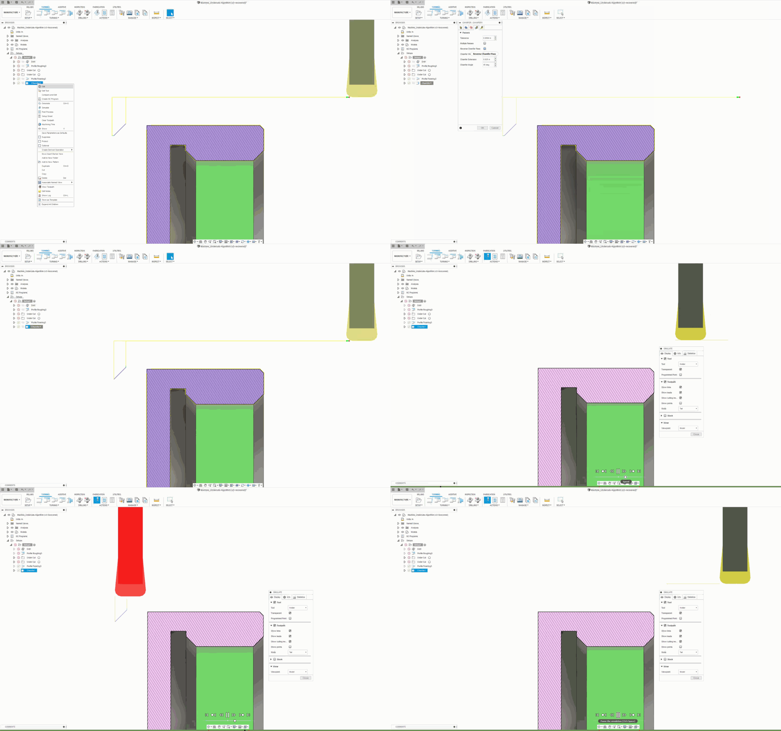
We also added the option to change direction of chamfer toolpath.
Minimum Retract for threading
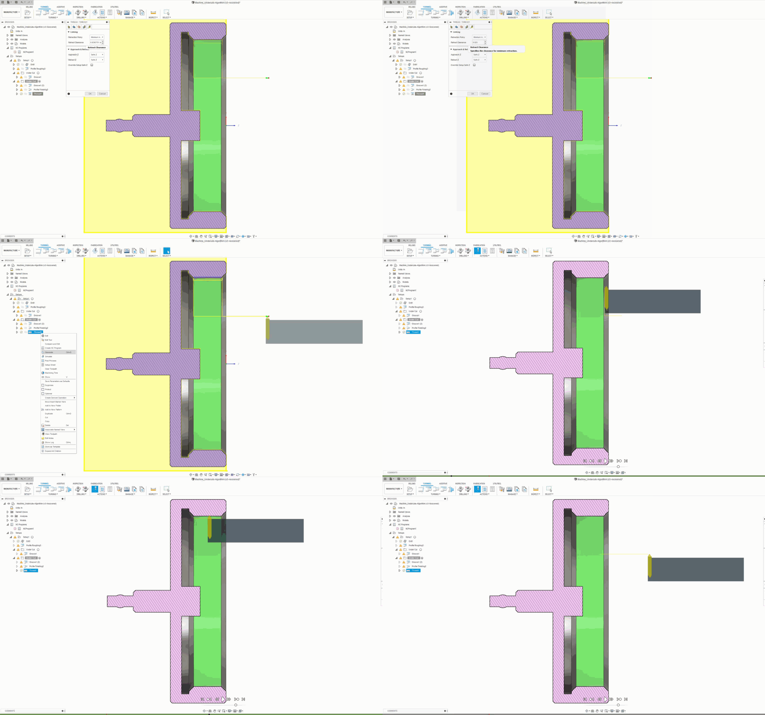
You can now set your own Clearance value added for between passes for threading.
Turning options in the Tool Library
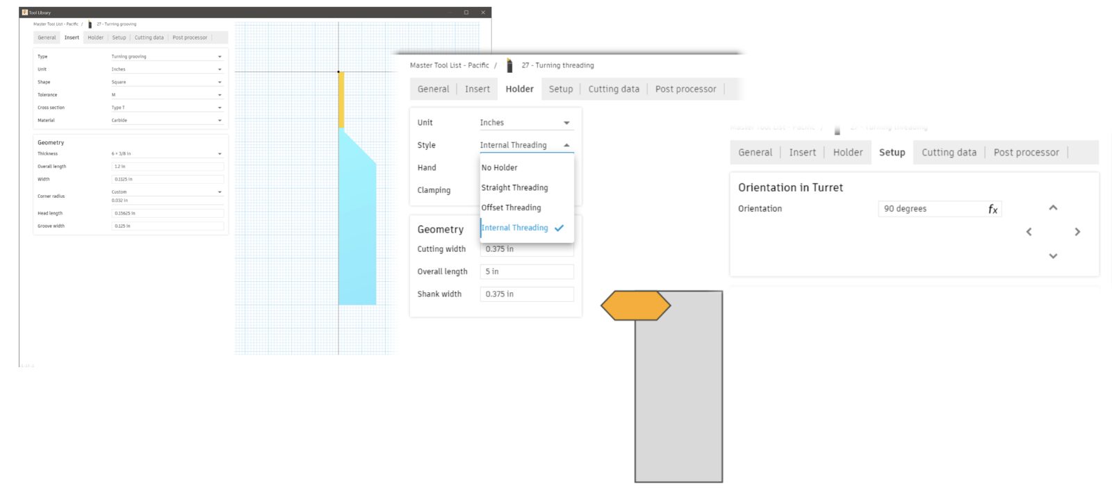
Turning options in the Tool Library now has Square Groove as an Insert > Shape type, Internal Threading as a Holder > Style type, and Automatic Orientation as an option Setup.
[/expand]
___
Improved! Tool Library & Machine Library Usability
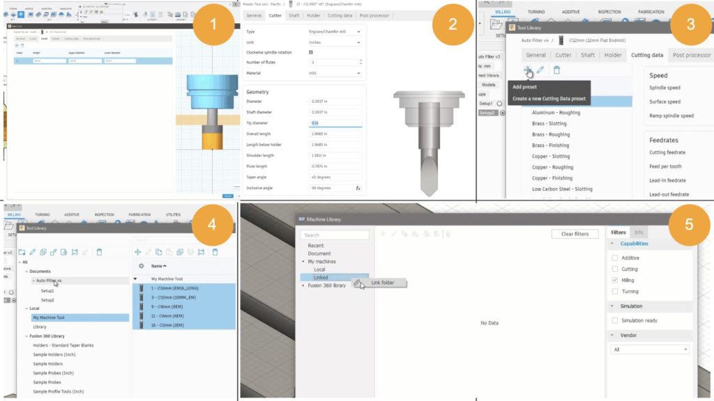
- Alignment of functionality
- Engraving Tool
- Add Presets
- Drag & Drop
- Local library folders for Machine Library
[expand title=”Learn more about each improvement”]
Alignment of functionality
Now in the Tool Library, you can use Escape to cancel, auto filter tool category, pin filters, show shaft segments, and edit holders.
Engraving Tool
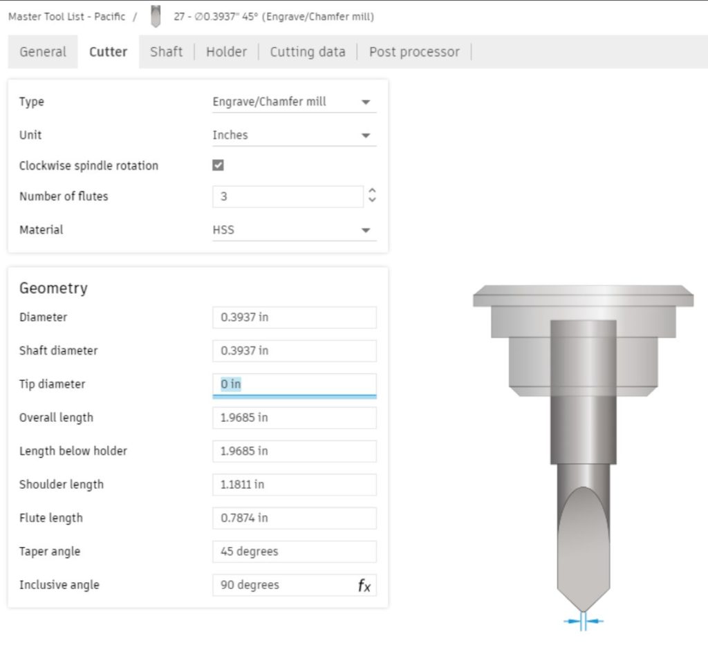
In the Geometry section of the Cutter tab, you’ll notice that we’ve added an Inclusive angle, and defaulted the Tip diameter to a zero.
Presets

You now have the ability to add a preset, reorder all presets, double click to highlight preset name. These changes will be reflected in the cutting data list on the main page.
Drag and Drop

For increased efficiency you can now Drag and drop tools from a document to a library or between libraries either individually or by multi-select. This will result in the tool/s being copied into the destination library.
Local library folders for Machine Library
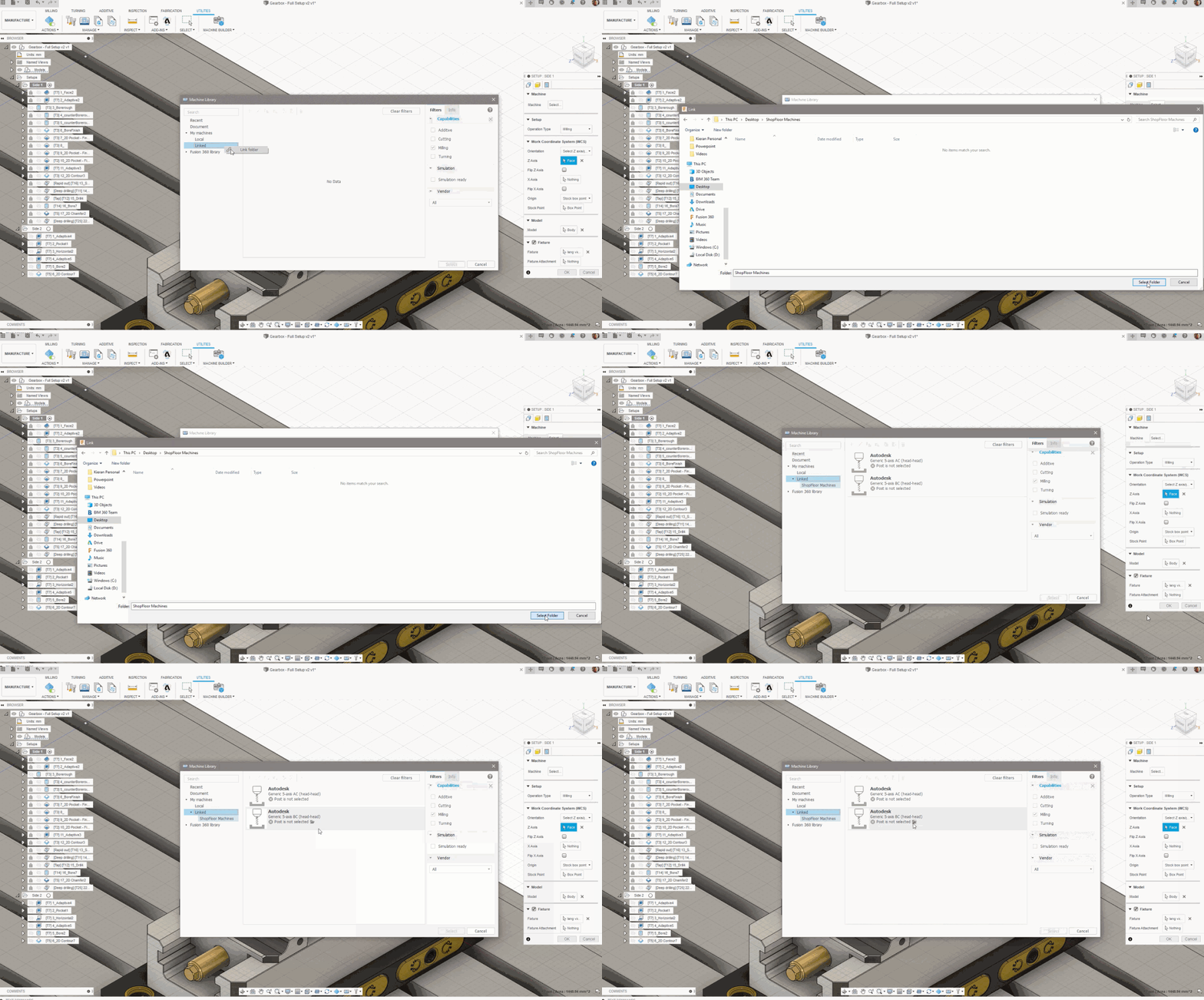
And use of local system folders for storage of post processors and machines.
– Learn how to use the linked folder in the machine library.
[/expand]
___
Improved! Nesting Usability
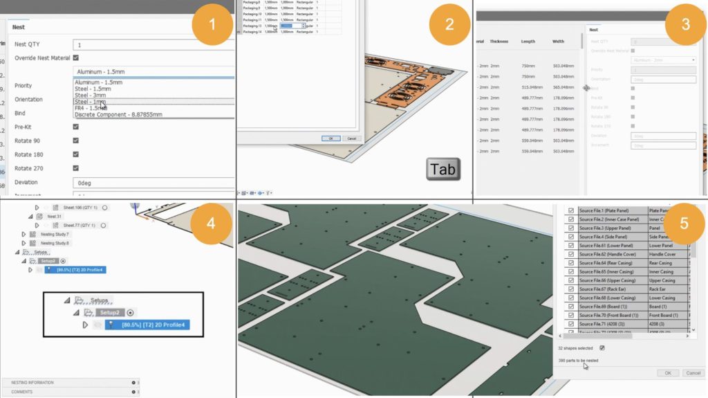
- Nest Material Override
- Tab Key Control
- Persist Dialog Size and Settings
- Improved Toolpath Calculation Time – 2D Profile
- Total Shapes Indicator
[expand title=”Learn more about each improvement”]
Nest Material Override
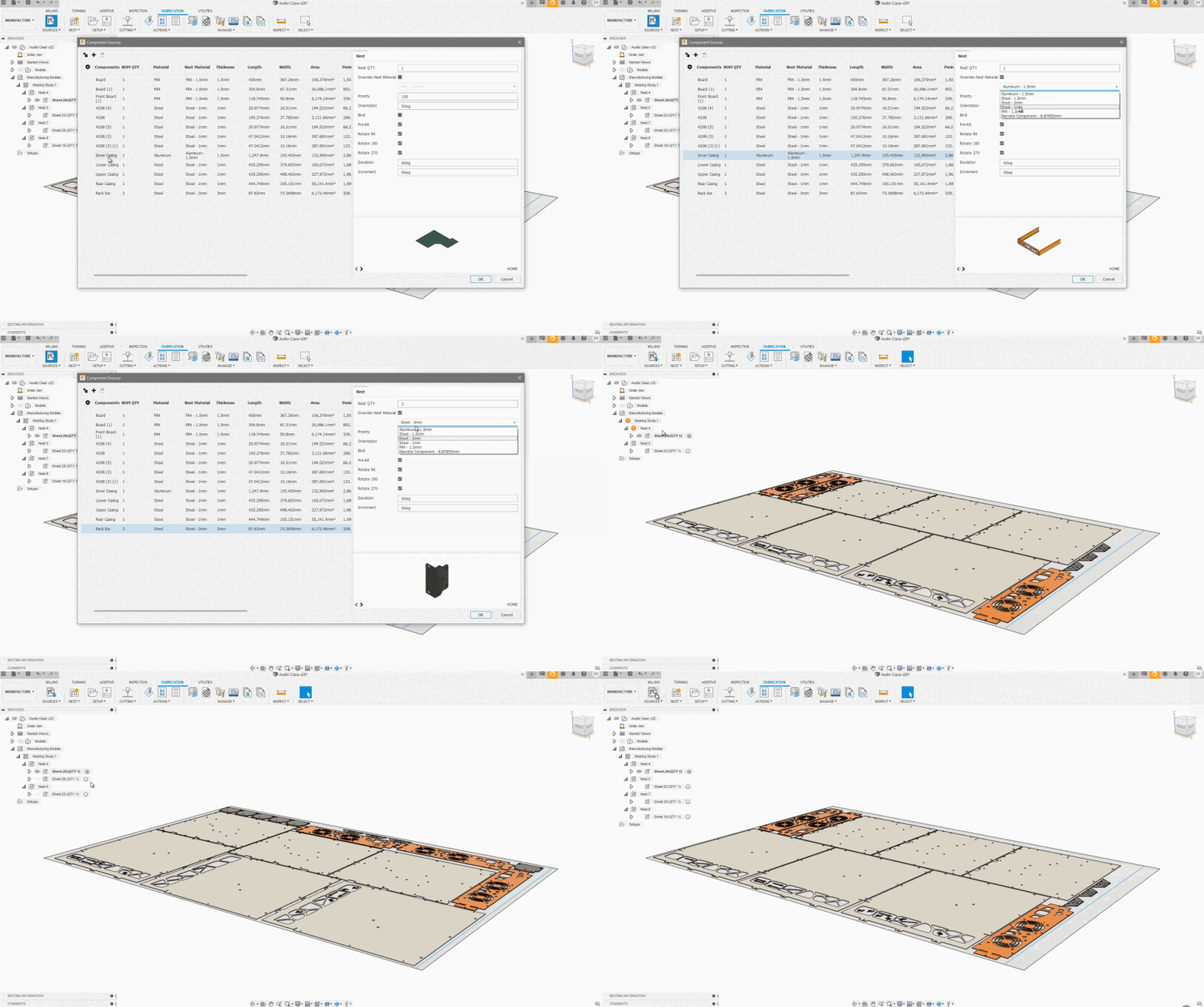
As you nest your components, you can now override the nest material, select the material you’re working with, and force parts onto the same or another nest with that same material.
– View the Nesting help documentation.
Tab Key Control
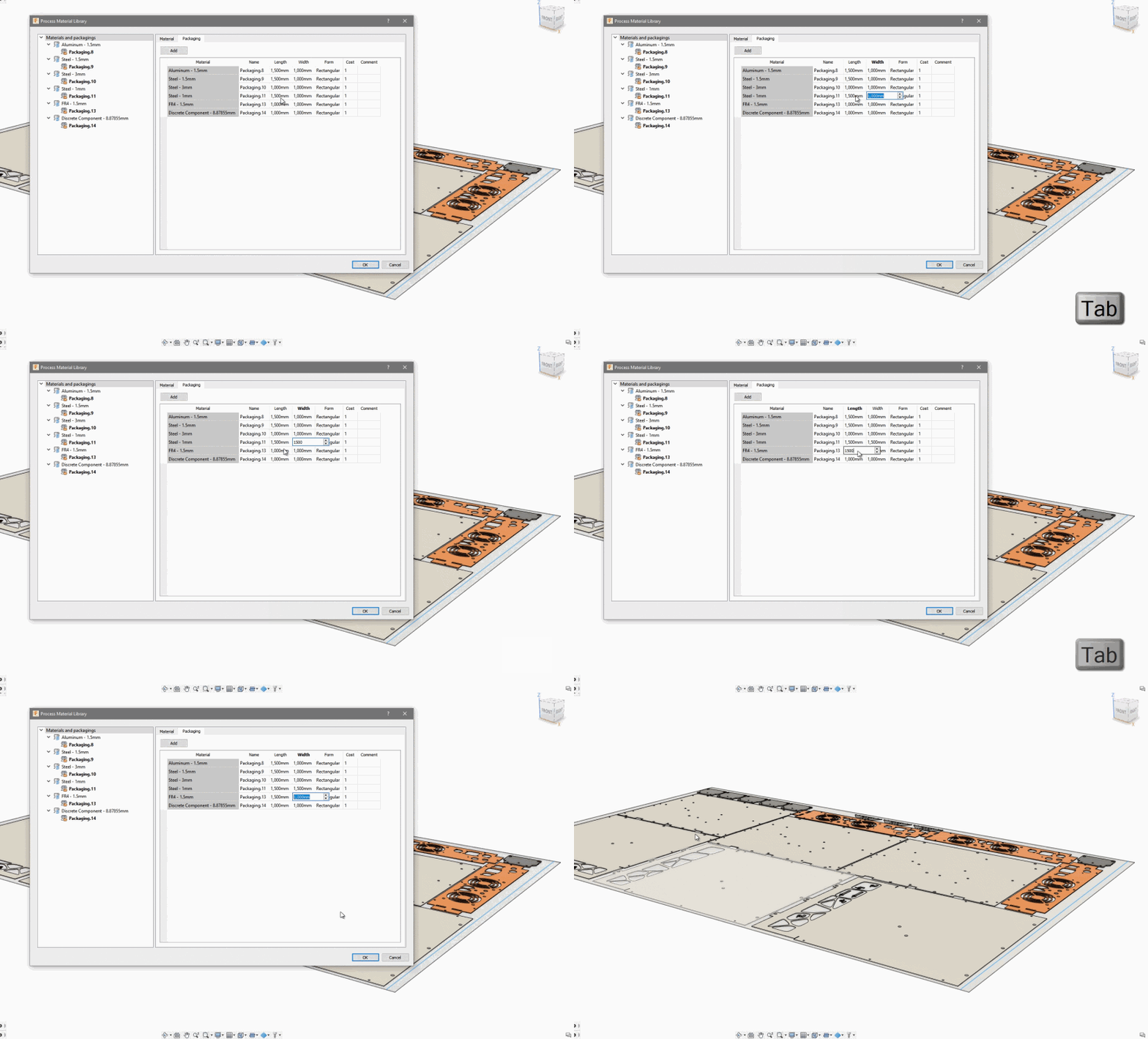
We’ve added the use of ‘Tab’ key to advance cursor and focus to next editable field.
Persist Dialog Size and Settings
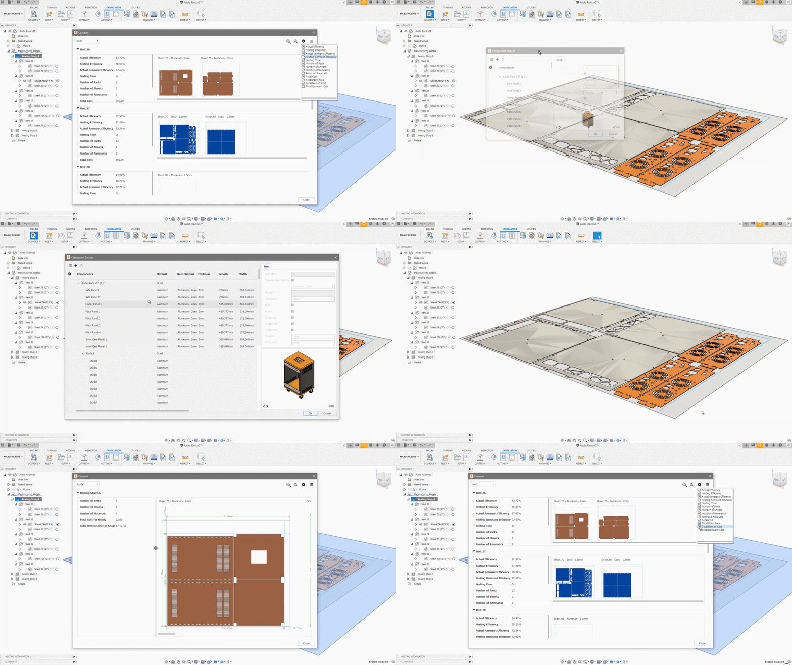
Another usability improvement is around the Compare and Component Sources dialogs. If you resize them, they will persist and will be remembered for the next time you pull up those dialogs again, preventing you from constantly needing to resize them to fit your needs.
Faster 2D Profile Toolpath Calculation Time
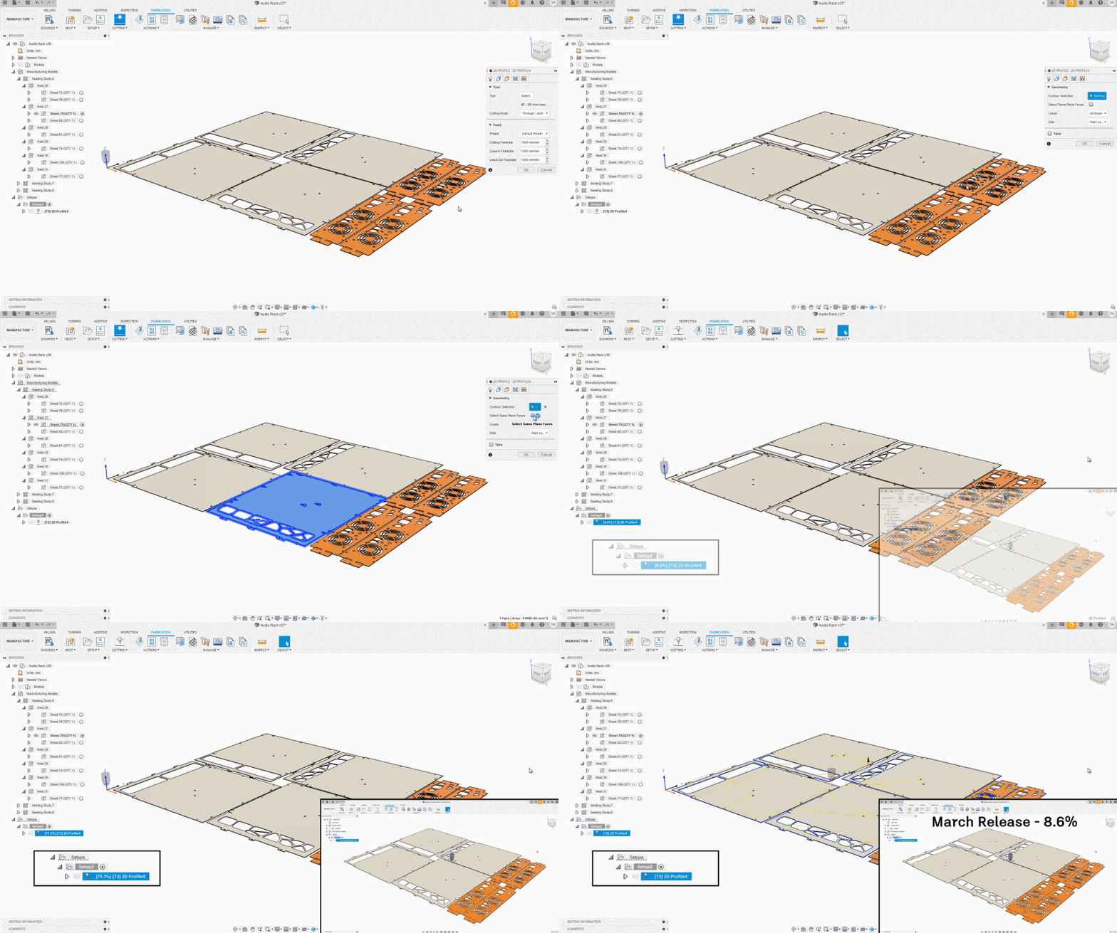
As shown in this example, 2D Profile toolpath calculations are now noticeably faster before. With the same toolpath, Fusion 360 is now about to finish the calculation in a matter of seconds, whereas back in the March update, it was still cranking away at 8.6%.
Total Shapes Indicator

Now in the Create Nest Study dialog, you’ll see the number of parts to be nested update with what you select. Now you’ll know exactly how many shapes will be used for your nest calculation.
[/expand]
___
Improved! Steep & Shallow Tool Strategy
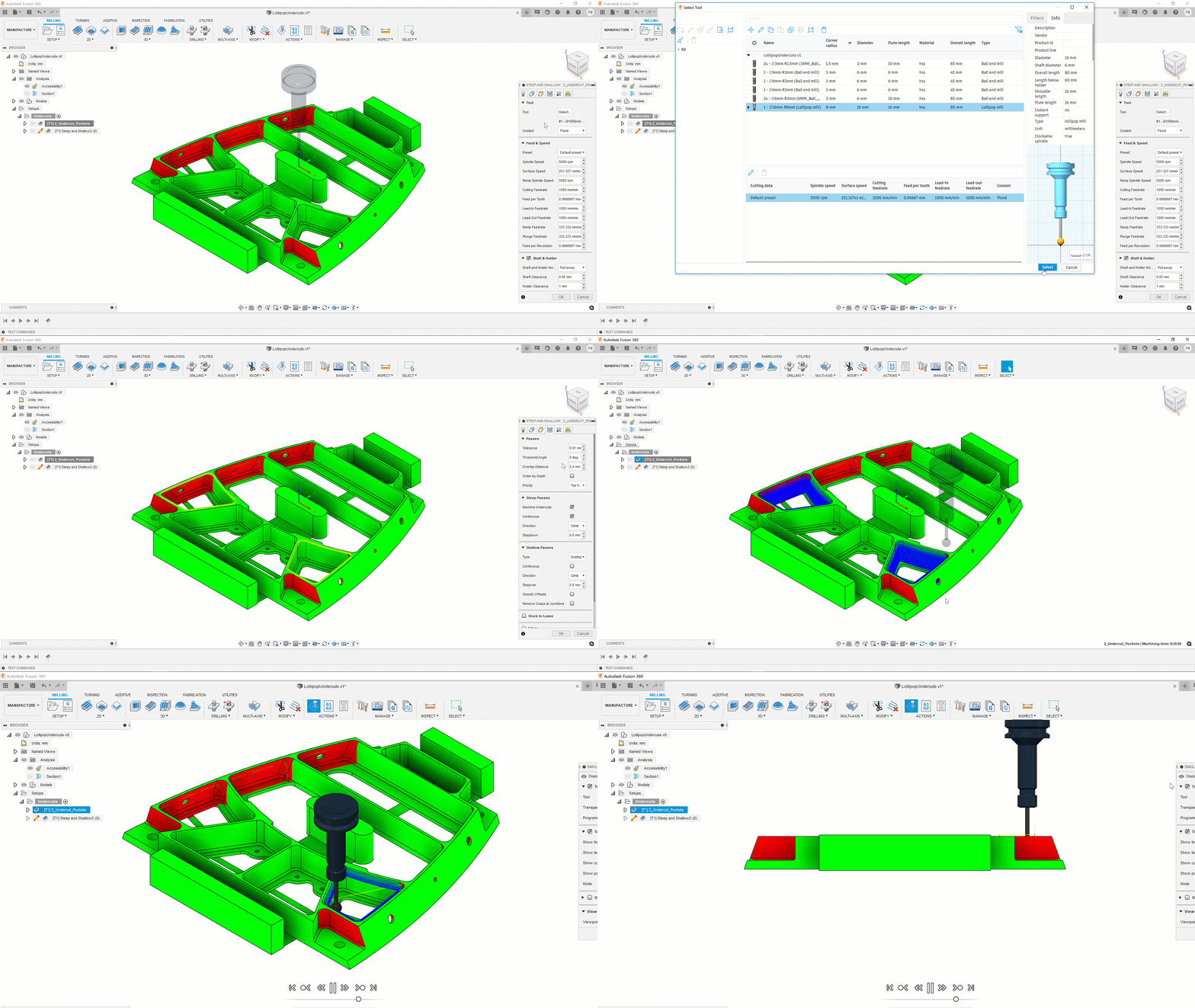
The Steep and Shallow strategy is typically used to machine freeform parts, often with a ball-nose tool. Machining flat regions with the same ball-nosed tool isn’t very efficient (Lots of passes to get a small cusp height) and the surface finish on flat regions isn’t as good as we’d get with a bull-nosed tool.
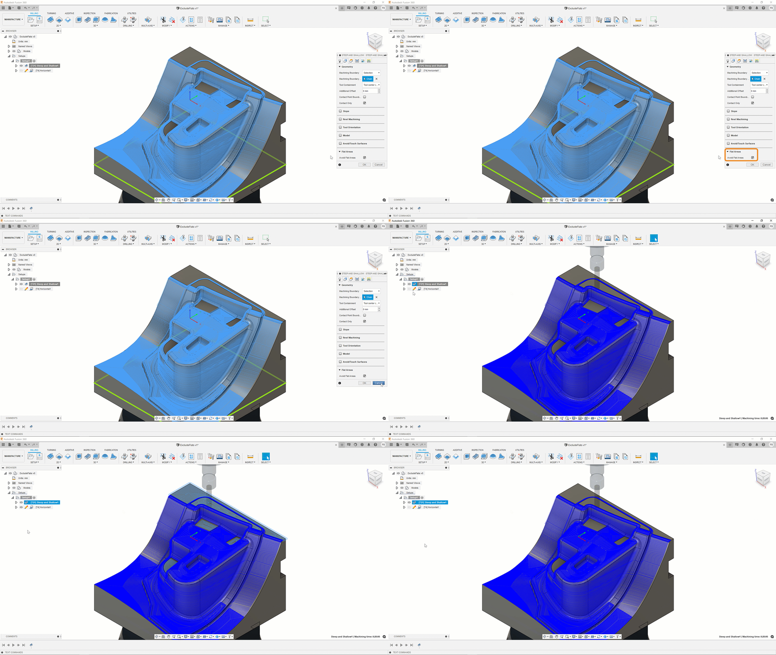
This option has been added to exclude any flat regions automatically. These excluded flat regions still need to be machined and this will typically be achieved by using a purpose-built strategy such as Horizontal, and a more appropriate bull-nosed tool.
– Learn how avoid machining flat regions in steep and shallow.
___
Improved! Consistent behavior across 2D and 3D Adaptive and Pocket strategies
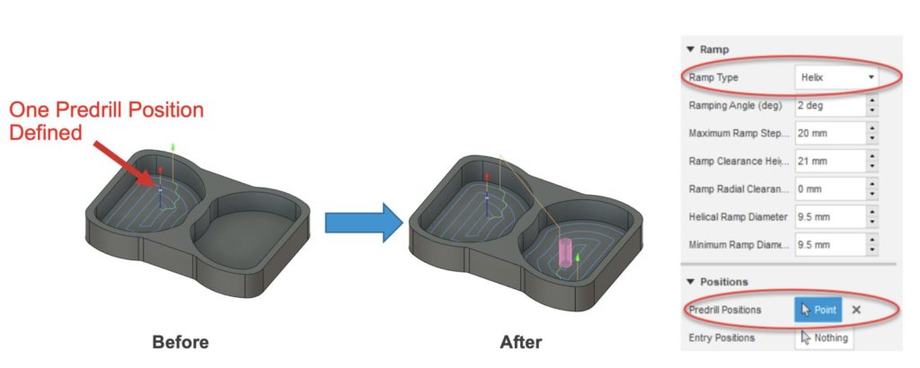
2D pocket now correctly enters the pocket using a helical ramp, while still using the predrill points for pockets where they are available.
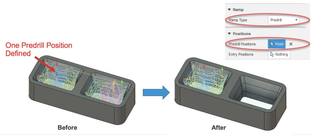
2D Adaptive now correctly ignores the pocket which doesn’t have a suitable predrill location. This is now consistent with other Pocket and Adaptive strategies.
___
Improved! Form Tool
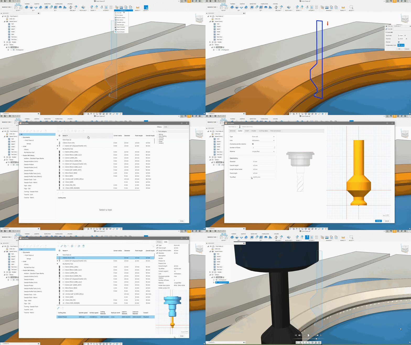
We added added Tip offset (Controls Z) and fixed offsets in the Form tool, so you can have more flexibility in how you want your toolpaths to work.
___
Additive
NEW! Support for HP Multi Jet Fusion printers
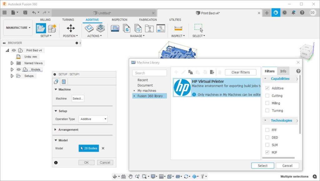
Fusion 360 Machine library now includes a virtual MJF printer to replicate an HP 3D printer’s build volume. When creating an additive setup, you can choose this machine and the bodies you select will be placed in this new build volume. Once you are ready to 3D print, you can send your additive setup to HP’s SmartStream 3D Build Manager software using the following App from Fusion App store.
Improved! Quick Access to Post

Simulate Additive Toolpath now give you the option to Post Process, giving you Easy access to Generate GCode right from the dialog without any extra clicks.
___
Improved! Infill pattern reorder

When you are editing your FFF print settings, you may notice that we reordered the type of infill patterns within the Sparse Infill Pattern drop-down menu. The new order is based on how sustainable each infill pattern is and their print success. We also updated all the print settings included with Fusion 360. This means when you select a print setting from Fusion 360’s Library you will be printing with gyroid infills by default. And if you wish it to change to a different infill style, the infill pattern order will look slightly different than it used to.
___
Improved! Smart Nozzle Priming
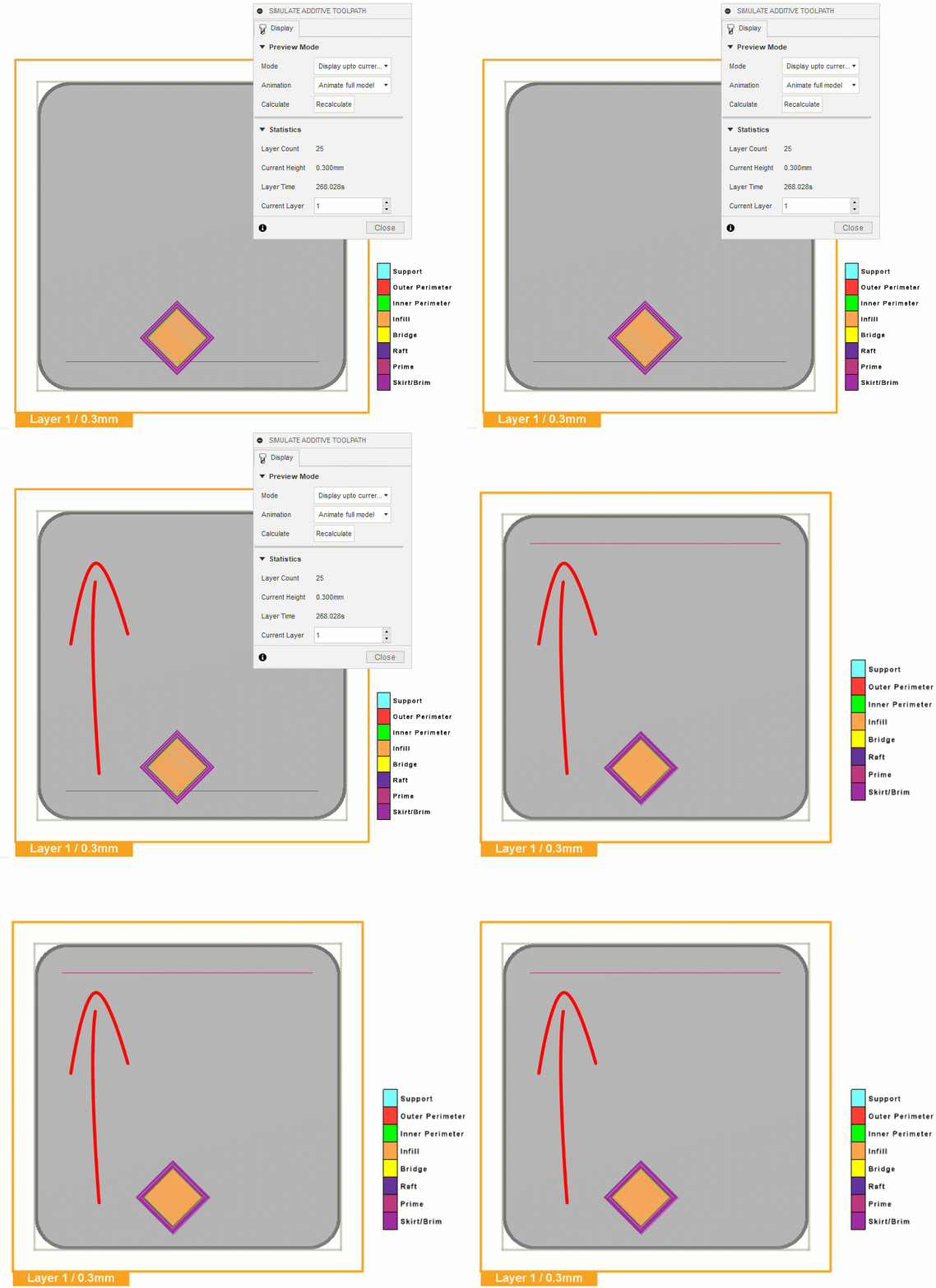
We have added some smarts behind the nozzle priming action in FFF 3D printing, so that the prime line does not interfere with the rest of the print. Before starting to print the model, the nozzle priming process extrudes a small amount of plastic along the edge of the build plate to get the plastic flowing smoothly. Fusion 360 already included a parameter to control the distance of the prime from the edge of the bed. But it always placed the prime line at the X axis by the front of the build plate. However, if you are printing a large part, or printing your parts close to that front edge, the prime line often interferes with the print. After this release, the prime line will look for another edge when it detects such interferences, so that you can print a problem free first layer.
___
Improved! Ultimaker 3D Printers

All the Ultimaker printers in Fusion 360’s Machine library now display a more realistic build plate when selected. This will give you better confidence on where you are placing your parts within the build volume.
Notices, Fixes & Known Issues
Notice: MacOS 10.13 High Sierra is no longer supported
As of this update, Fusion 360 no longer supports MacOS 10.13. This means that Fusion 360 will no longer be receiving updates on any MacOS that is running MacOS 10.13 or lower. Fusion 360 is not available to be downloaded and installed on MacOS 10.13 or lower, from this point, if uninstalled.
To see details around this, our extended list of fixes, as well as known issues, check out this forum thread in our support forum.