(V.2.0.16009)
This update addressed one of the key issues that was causing an unexpected spike in crashes for some of you, especially for those of you running Fusion 360 on Windows machines. We wanted to release the fix now instead of waiting for the next big update so that you can get the fix as soon as possible and continue your work without worries.
(V.2.0.16007)
– We fixed a crash issue that occurred when selecting a tool after filtering tool type.
– We fixed an issue that occurred when using Offset Plane and inputting a value from your keyboard.
– A few of you on the forums reported an issue within Fusion 360 Electronics that occurred when transferring 2D PCBS to 3D PCB, this issue occurred when your OS region was set to either French or Dutch.
April 2023 Minor Product Update
(V.2.0.15995)
In the April 2023 minor product update we addressed key issues reported through our support channel, forums, Fusion 360 Insider Program, as well as our manufacturing Customer Advisory Board. Thank you everyone for your ongoing support! Let’s get into the key updates:
Design Fixes:
- kdh4287 reported an issue within the new export dialog box workflow where Fusion 360 removes the user defined body name and replaces it with the component name. This change made it so you had to rewrite your part names when exporting STL files. This workflow is now fixed, and you will be able to accurately name your exported mesh files with ease.
- We fixed an issue where the Viewcube was displayed incorrectly in non-English languages.
- A few of you on the forums reported an issue where high DPI scaling was not working as intended. This is now fixed.
Manufacture Fixes:
- We fixed an issue within wrap 2D Contour where trimming a chain and setting the negative value for start/end extensions would cause an error.
Electronics Fixes:
- A few of you on the forums reported a graphics issue in Fusion 360 Electronics where a black screen would be displayed instead of the Schematic and Board design areas. This is now fixed.
- Previously, if the pads in Fusion 360 Electronics were rotated (but not with 90 degrees) and the polygon edges are also with some angle, the pad (with the same signal as polygon) was displayed as a gap/cutout. This is now fixed, and the pads should display as expected.
- We made many asset management improvements and addressed multiple CERs in the Electronics workspace.
Live with the Experts | Live from the Birmingham Technology Center!
What’s New in the April 2023 Release
Check out the following video to see the latest and greatest in Fusion 360.

April 2023 Major Product Update
(V.2.0.15775)
Usability
NOTICE: Important OS support information after April 2023
This update marks the end of support for legacy Operating Systems like macOS 10.15 Catalina, Windows 7, and Windows 8/8.1. While old versions of Fusion 360 will continue to work on these OSes for some time, the latest and greatest releases now require a minimum OS of macOS Big Sur 11 and Windows 10 (v1809) or newer.
While we try to support as various OS’s for as long as possible, this often comes at the cost of embracing newer technology and developmental efficiency. What we gain from dropping legacy support is the capability to leverage the latest and greatest technologies supported by Apple and Microsoft.
While the April update will still be native x86_64 code, the update is a crucial step in our quest to create a native ARM-based Fusion 360 client on Apple silicon (which we hope to show you later this year). In addition, this update will greatly facilitate our ability to bring high DPI scaling support to Windows.
Updated Sign-in Experience
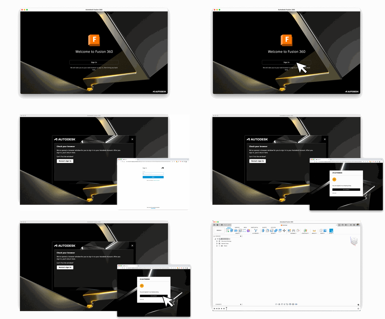
For those of you signing into Fusion 360 after this update, you may have noticed the new sign-in experience. Now at the log-in screen, clicking on the Sign In button will take you to a separate web browser to continue the log-in process. Once you’re done, clicking on Go to product will bring you back to Fusion 360 and you’ll be logged in. We updated how you sign into Fusion 360 for a few important reasons.
- This new experience adds a new layer of security, allowing companies to leverage their own single sign-on policies.
- Also, you can now use your own password managers to fill in your account info. This was a pain-point we’ve heard from many of you, and we’re glad to say that it is now possible.
- Lastly, this makes our sign-in consistent across multiple Autodesk solutions.
Sign-out experience of Fusion 360 will behave the same way as well.
Performance Improvements
Like our past updates, we continue to improve usability performance across the platform. Here are some key highlights for this update:
- Saving design files with a large local .SQL cache file is now up to 10x faster
- Mirror component for large design files is now up to 8x faster
- Opening large design files is now up to 51% faster
- Window-selecting component under Move command has improved 58%-132%
- Moving components in large design files has improved up to 40%
- Invoking Pattern command after selecting many bodies from Browser has greatly improved
- Expanding Document Setting Browser to change Thread Type when convert the model into Direct Modeling is now greatly improved
F3D and F3Z files should no longer get caught in email filters
Some Fusion-generated files were generating an embedded .INF file to define the model’s material properties. This clashed with email file scanners’ heightened security policies, causing false positives when the .INF was detected. Files generated with the April release and later should no longer contain embedded .INF data and should once again withstand email scanners’ scrutiny.
Design
New Blend Curve Command in Sketch
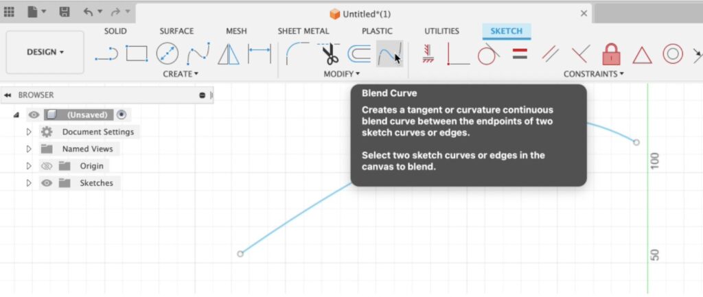
Now in the Sketch contextual workspace, you can use the Blend Curve tool to create a tangent (G1) or curvature (G2) continuous blend curve between the endpoints of two existing sketch curves or edges. The live preview helps you make better choices related to continuity. This addition is a fast and easy way to connect existing geometry.
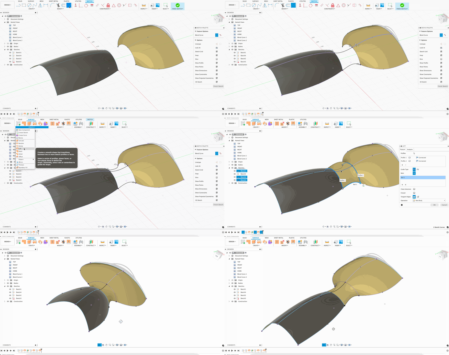
Learn more about how to use Blend Curve.
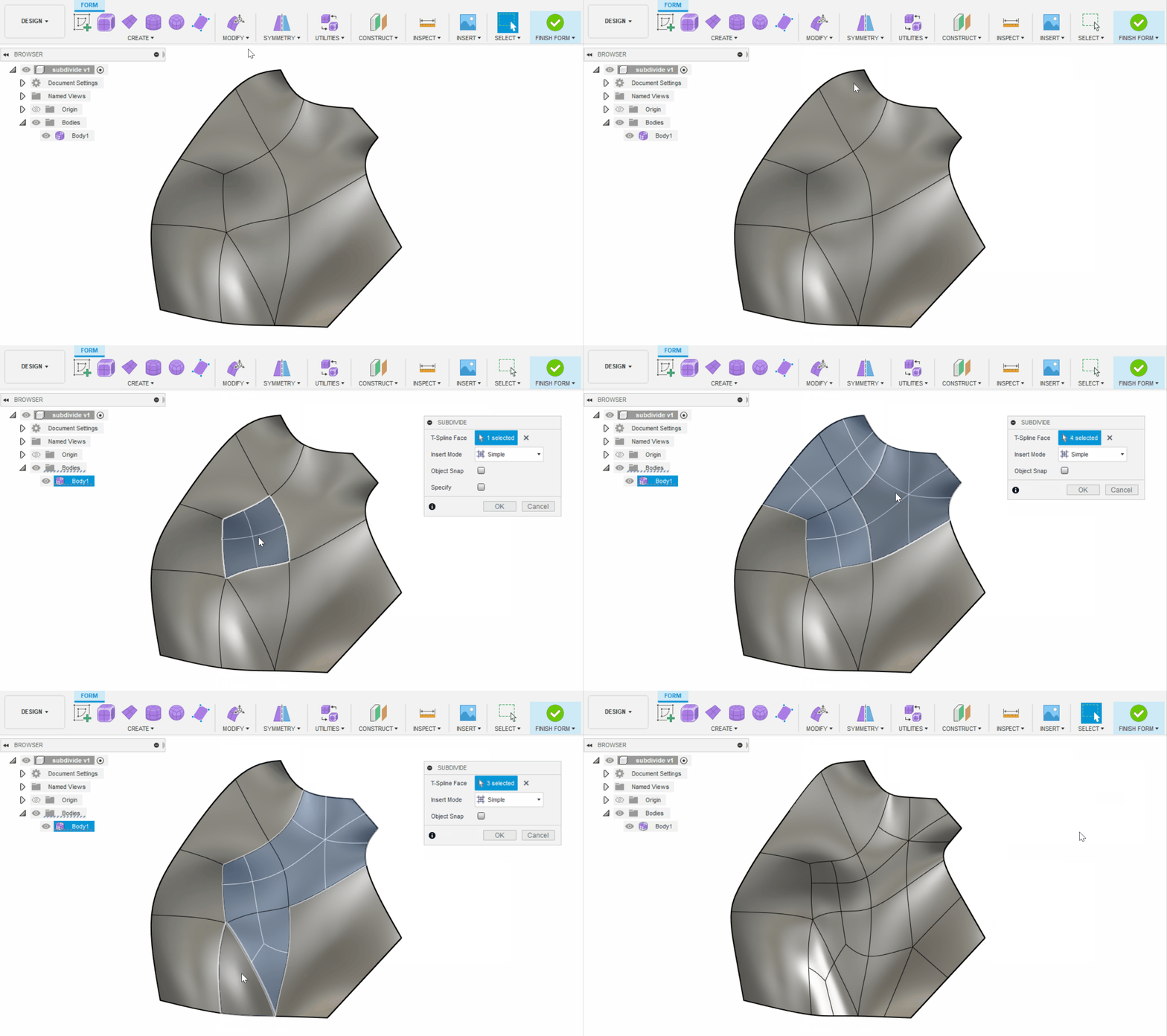
Improved Face Selection in T-Spline Subdivide
Previously, you were unable to select any additional faces after the T-Spline Subdivide command was invoked and an initial selection was made. Now you are able to easily select additional faces to subdivide. Preview graphics will be displayed on all selected faces.
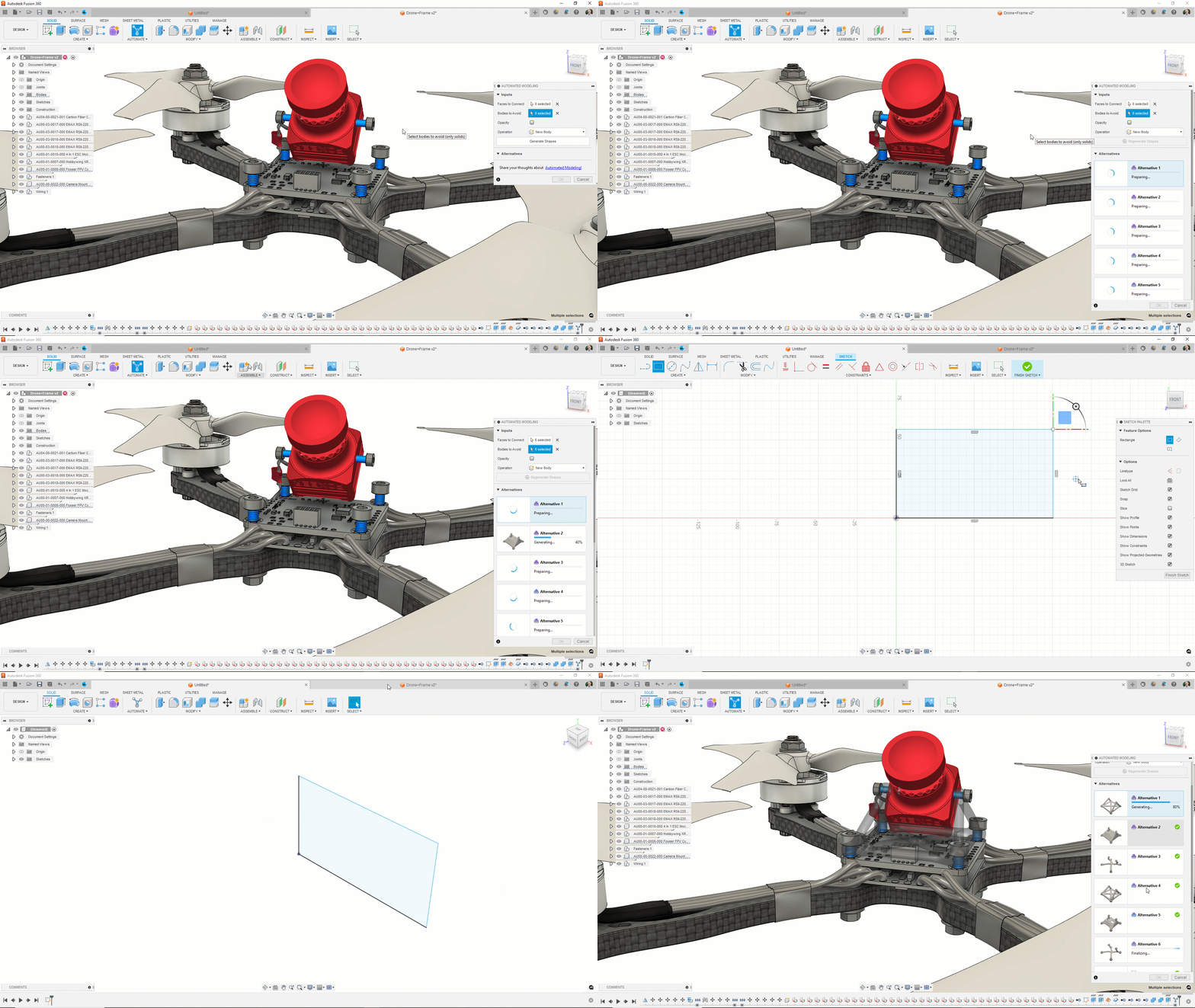
New Support for Document Switching While Waiting for Results in Automated Modeling
In this update, we have improved Automated Modeling to be more aware of those of you who want to multi-task while alternatives are being generated on the cloud. Previously, if you switched to another document while Automated Modeling was generating results, it would close the command, forcing you to start over. Similarly, if you started another command while Automated Modeling was running, it would close the command, again, forcing you to start over. With these improvements, Automated Modeling will now run in the background when switching from document to document, allowing for improved multi-tasking across many documents.
Improved Insert X-ref behavior
Previously, when a design with a milestone is inserted, Fusion 360 automatically inserts the latest top version of a design rather than respecting the existing milestone. We’ve corrected this behavior so now the workflow will insert the latest milestone version of the design. This means minor saves beyond the milestone will not be exposed until the next milestone is created.
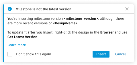
Learn more about inserting designs.
Electronics
Improved Electronics Graphics
We switched our graphics engine and are now using GPU rendering as our graphics back-end. This should make things look a lot more crisp and less pixelated, it’s as if we turned anti-aliasing on. The difference is noticeably better and improved performance.

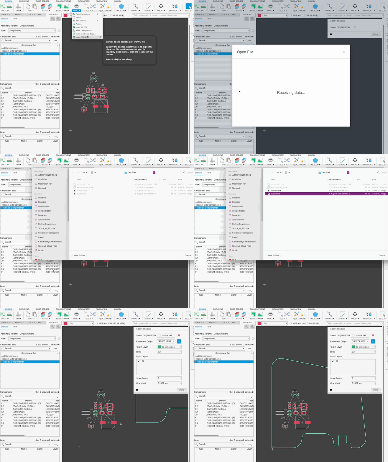
Insert DXF/DWG is Now a Native Command
Previously, the command inserting DXFs & DWGs was executed via a ULP and limited. It’s now possible to insert DXFs & DWGs and target them to a specific layer as well as change scale/position all through a handy wizard.
New Option to Paste on Active Layer
Previously, if you tried to copy and paste objects existing on a source layer, the target layer always matched the source layer. In many cases, you may have wanted to paste the object onto the active layer. Now you can choose whether to paste the object on the source, a new target or active layer.
New Choice to Keep the Via Source Net When Pasting Vias
It’s now possible to choose whether to keep the Via source net when pasting Vias. Previously, when patterning GND Vias in the 2D PCB, the resultant patterned GND Vias were not connected (they were created as GND1, GND2, GND3… respectively). Now, patterned GND Vias can either retain the source net or target a new net with a user toggle option.
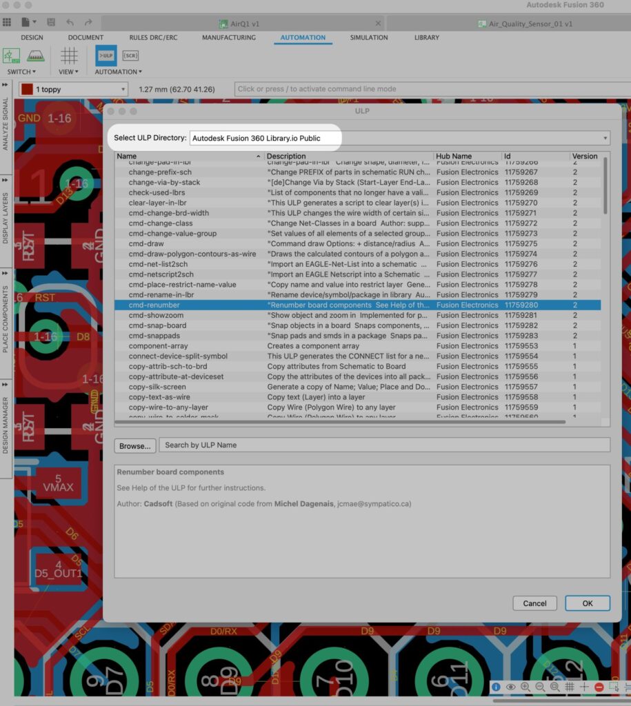
Electronics Assets Now Stored Through Fusion Cloud
Previously, locally stored Fusion 360 Electronics vendor-supplied/sample utility files (including Design Rule Files (DRU), Scripts/User Programs (SCR/ULP) and CAM files) could only be accessed through your local drive. You can now browse these files hosted in the Fusion cloud directly within Fusion 360!
Tabbed Panels are Now Collapsible
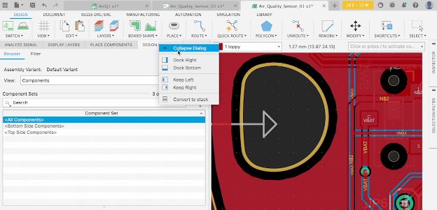
Previously, when you wanted to collapse a tabbed panel directly, you had to instead first ‘convert to stack’ now you will be able to simply ‘collapse dialog’.
Improved Signal Integrity Extension
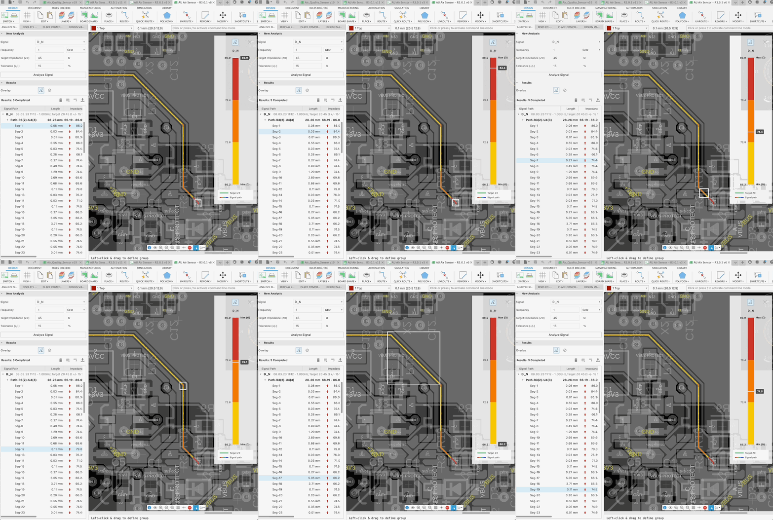
For our Signal Integrity Extension, we improved geometry analysis so that it gives better and more correct segments. We also fixed several bugs in the UI.
Simulation
Improvements to Simulation Pre-Check
We have added some better guidance to the Simulation Pre-check dialog:
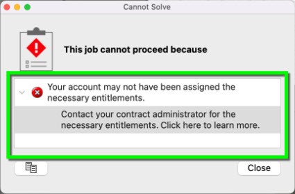
- Pre-check now lets you know that you are missing the Simulation entitlements and will ask you to contact your contract manager to get the right entitlements assigned to your account.
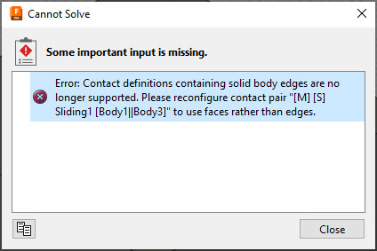
2. The pre-check dialog now captures issues with edge-based contact and will identify the problematic area for you to go back to and modify.
Heat Sources Defined on Contact Surfaces Now Recognized in Nastran Solver
We have added an improvement in the Nastran solver where it now recognizes heat sources defined on contact surfaces correctly, allowing you to see more accurate results for your Thermal and Thermal Stress Simulations.
New Additional Warning for Body/Component or Settings with Visibility Off in Simulation Workspace
Turning off the visibility of a body/component or a particular setting in the Simulation workspace does not exclude them from being used during the Simulation run. Previously we showed this just as a Pre-check warning. Now, you will be reminded ahead of time, so you’re not caught off guard at a later step.

Generative Design
Symmetry Graduates from Preview
Previously available as part of our Experimental Generative Solvers and Features preview, the Symmetry Plane option has now graduated out-of-preview and is officially part of the Generative Design Extension.
The Symmetry Plane tool enables you to define up to 3 orthogonal planes of symmetry to enforce in the design outcomes. These symmetry planes will also be present in the outcomes and will drive symmetric editing in the T-spline form body. The Symmetry Plane tool can be found on the Design Space panel of the toolbar in the Generative Design workspace.
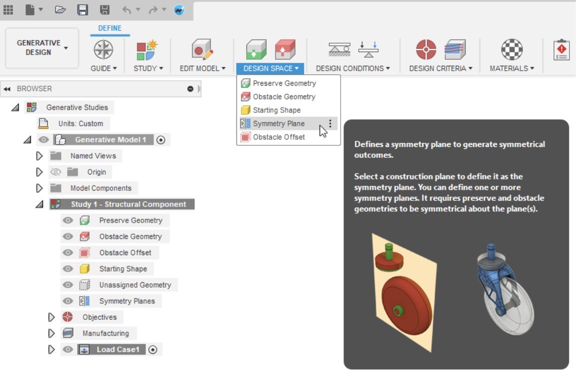
Learn more about Symmetry Plane.
Improved Study Settings Dialog
We improved a few aspects of the Study Settings dialog so that it is easier and more intuitive to use. You will now see updated nomenclature, slider tick marks, and new tooltips explaining what high/low-resolution setting means.
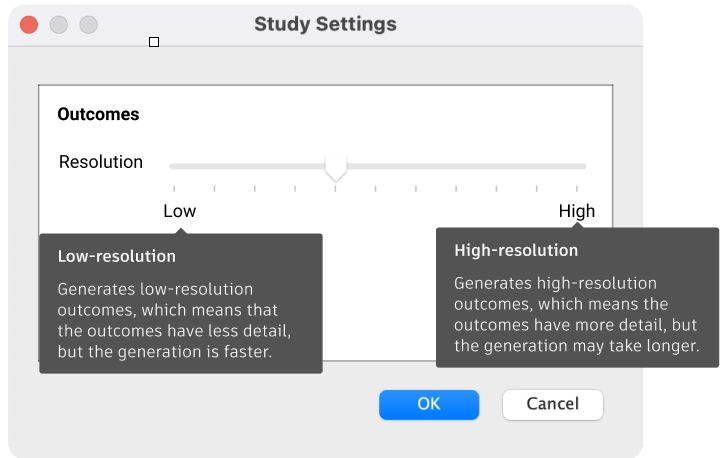
Learn more about Study Settings.
Alternative Outcomes Option is Retired
In this release, we reached a major milestone in our Experimental Generative Solvers and Features preview and our retiring the Alternative Outcomes option that was part of the Study Settings dialog. We are now fully standardized on our new solver technology for all non-preview functionality in the Generative Design extension. As a result, you will no longer see multiple duplicate outcomes that look the same and clutter up your Explore environment. The remaining functionalities in the Experimental Generative Solvers and Features preview are Modal Frequency Limits, Buckling Limits, and the option to Remove Rigid Body Modes for under-constrained models.
Learn more about Experimental Generative Solvers and Features Preview.
Drawings
New Automatic Centerline and Center Marks feature
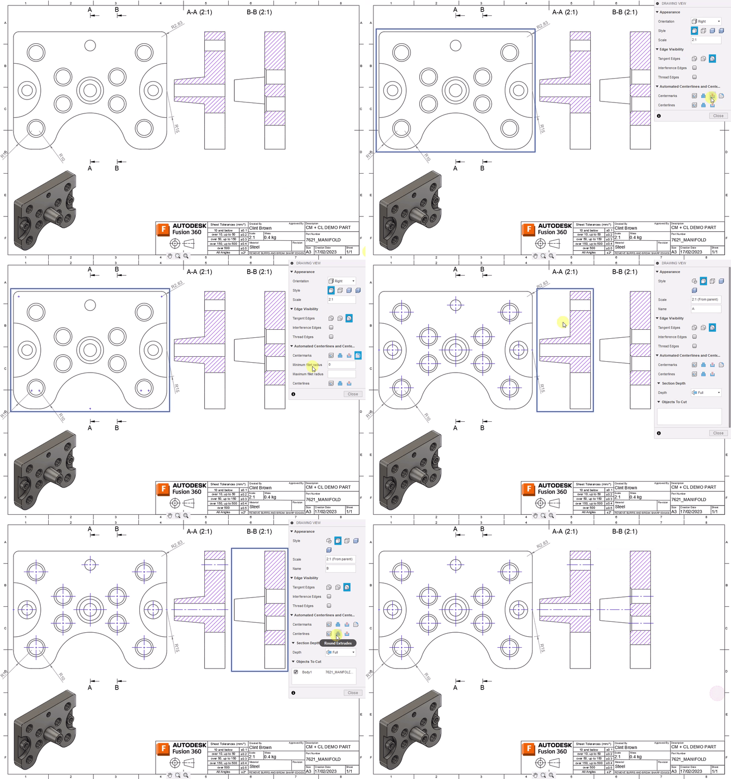
With the new automated center mark and centerline feature, you can now quickly create center marks & centerlines for all holes. We’ve even included the ability to create center marks and centerlines on extruded (or revolved) bosses and cuts. Additionally, center marks can be set on or off by size of radii.
Learn more about creating automated center marks and automated centerlines.
Manufacture
New Incline Flats for Flat Machining Toolpath
Flat machining now includes intelligence to give you a multitude of automatically calculated 3+2 toolpaths for all inclined planes while the connection moves are all simultaneous 5-axis. This is a great addition to the Flat strategy, which automates the toolpath to machine all the flats on your parts, inclined or not. Inclined Flats detects the max and min tilt angle range defined by you, references either the setup z-axis or the tool orientation for the angles defined and finds all the flats within that range and cut them.

Learn more about Incline Flats
New Deburr Toolpath (Machining Extension Preview)
When you machine parts, there is often a “flash” of material left on the edges of the machined parts called “Burrs”. They can be anywhere between 1- 10 microns and almost always need to be removed as part of manual process after machining. The new Deburr toolpath (found under the Milling Tab > 3D Panel) aims to address this and is typically used on finished parts. Use it on areas where you have a corner between a vertical and a horizontal face or where two flat surfaces change direction from one another. The toolpath runs the tool along the edge just enough so that the sharp burrs are removed, reducing the need for manual processing. Deburr works for 3, 4, and 5-axis milling, uses the side portion of the tool, and lets you define the gouge value. This is currently a Machining Extension Preview feature and will be released as part of the Machining Extension.
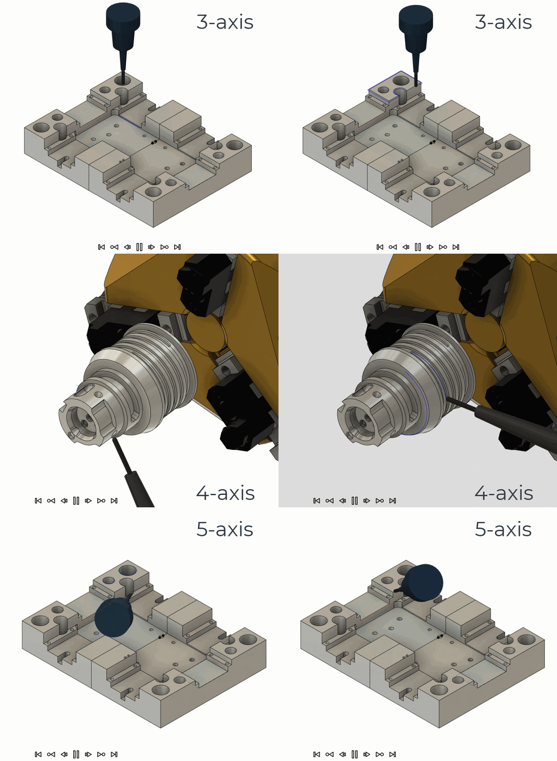
Learn more about Deburr Steps.
New Corner Toolpath (Machining Extension Preview)
New for this update, we’re introducing a new toolpath called Corner Finishing (found under the Milling Tab > 3D Panel). This technology was brought over from Powermill and is currently available to try as a Machining Extension Preview.
In Fusion 360, you already had a corner-style finishing strategy referred to as “Pencil”. In PowerMill, there are 3 main strategies: Corner Finishing, Corner Multi-pencil Finishing and Corner Pencil Finishing. Pencil in Fusion 360 machines all model segments ‘along’, meaning the tool will run up and down steep corners, potentially creating dangerous cutting conditions. The new Corner Finishing strategy can cut along for shallower regions and across for steeper regions to avoid damaging the part and tool.
In future releases we plan on adding capabilities to address variable corners/fillets as well as adding capabilities from Multi-pencil Finishing from PowerMill to create a combined unified strategy within Fusion 360.

Learn more about Corner Finishing
Global Planes Now Displayed in Section Analysis for Additive Setups
Section analyses applied to Additive manufacturing setups will now automatically display the Global planes based on the machine origin. When you add a section analysis to see how the parts / support interact you will now notice that the XY, YZ, and ZX planes are now automatically visible / selectable. This improvement makes it easier to select a section plane specially for organic looking parts which do not have any planar faces to select for section analysis.
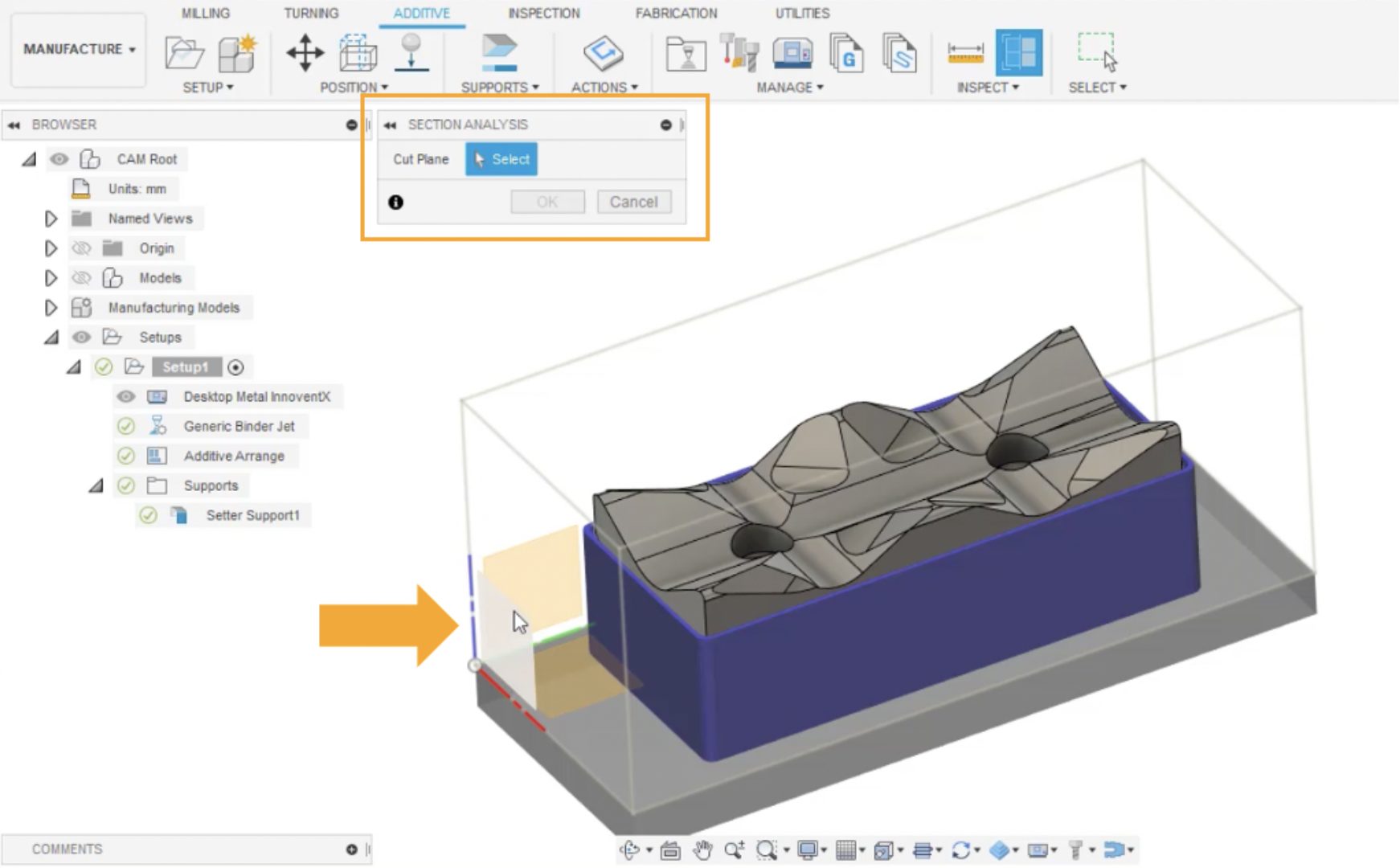
Learn more about Section Analysis.
New Additive Brace/bracing Cross-connections between Bar-supports
Additive Brace/bracing cross-connections between bar-supports helps you create lightweight, strong bar supports, and minimize wasted material usage as well as labor involved in post processing printed parts.
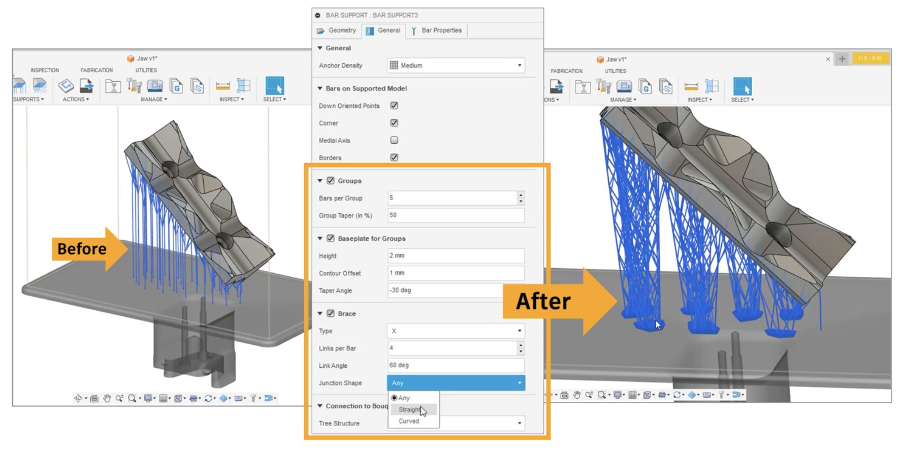
Now when you create an additive setup with an SLA/DLP and or Metal printer (this does not apply to FFF printing), you will see new settings for bar supports around “grouping, base plate for groups and bracing. This allows you to have more control over how you create your bar supports.
Learn more about adding bar supports.
New Ability to Import Custom Process Parameters (PRMs) for Metal Additive Simulation
Additive Build Extension users now can import custom PRM files (created using Netfabb Local simulation) to Fusion 360’s metal powder bed fusion print settings. This will allow them to simulate parts printed with any material/print setting a custom PRM file may contain.
Learn more about how to change a print setting’s associated PRM file.
Copy/Paste Presets – Multiple Presets to Multiple Tools
We’ve improved the current Copy/Paste Preset functionality so that multiple presets from a single tool can be copied and subsequently pasted to multiple tools of the same type. For example, you can select 3 presets from an existing flat end mill and paste them across 5 other flat end mills. Typical list selection controls are supported, like shift-select to grab all items in a range, or control/command-select to grab individual items across the list.
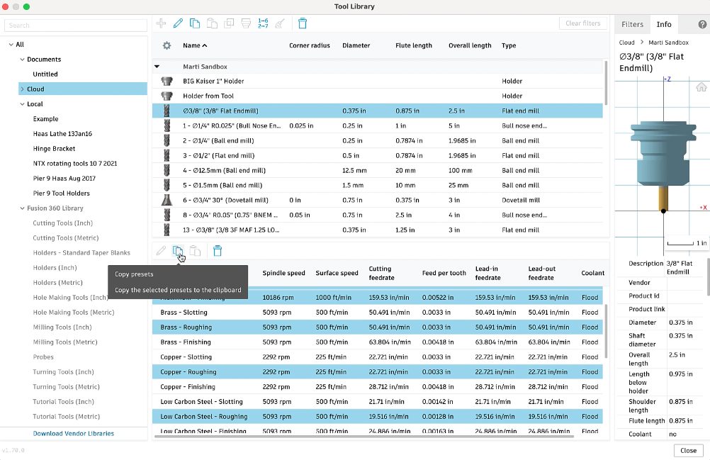
Learn more about working with tool presets.
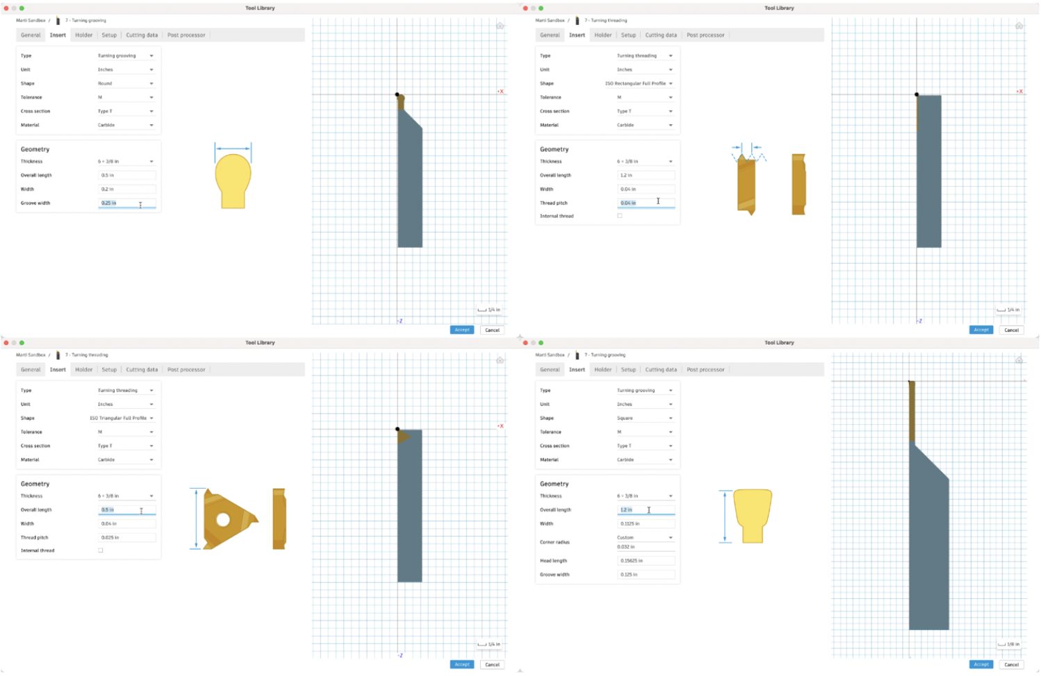
New Visuals for Threading and Grooving Turning Tools
When creating a threading or grooving turning tool, previously there was no center image or visual to help display what the insert dimensions corresponded to. Now you will see the appropriate visual for round grooving inserts, rectangular threading inserts, and square grooving inserts.
New Dynamic 3D Preview of Tools and Tool Holders in Tool Library (Public Preview)
This public preview changes the 2D preview of tools and tool holders in the Tool Library to a dynamic 3D preview that can be manipulated with pan, zoom, and orbit controls. If you have too much fun and lose sight of the tool or otherwise want to return to the original view, there’s a “Home” button in the upper left corner to snap back to the original view.
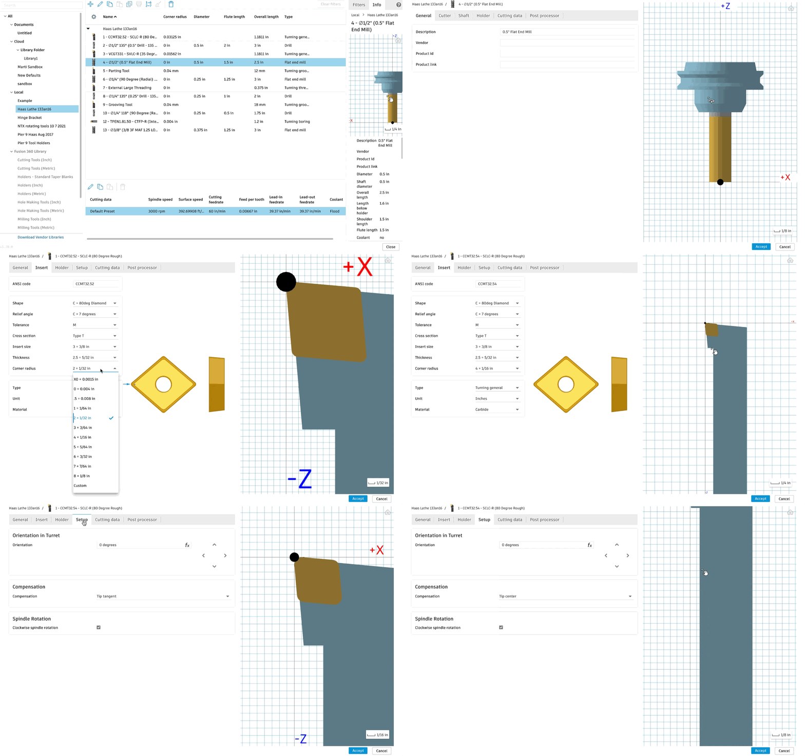
This preview is especially valuable when creating or editing milling tool assemblies where the tool is much smaller than the holder. Same for turning tools where the insert can be difficult to see in detail when a holder is applied.
This is currently under public preview as there may be driver or other hardware issues that we were unable to catch in our tests. If you experience issues, please let us know so we can make sure your hardware is supported!
Learn more about the Tool Library preview.
Improved Drilling Toothpath Dialog
In the January update, we made a UI change to the drilling toolpath dialogue where you can designate between using FPR (feed per rev) or FPM (feed per minute). This had unintended consequences in only showing the active parameter. We heard your feedback about the benefit of having both FPR & FPM displayed at the same time and in this update, brought the field back (but in a read-only mode). The read-only mode will provide a visual sanity check between the two output types that were previously missing.
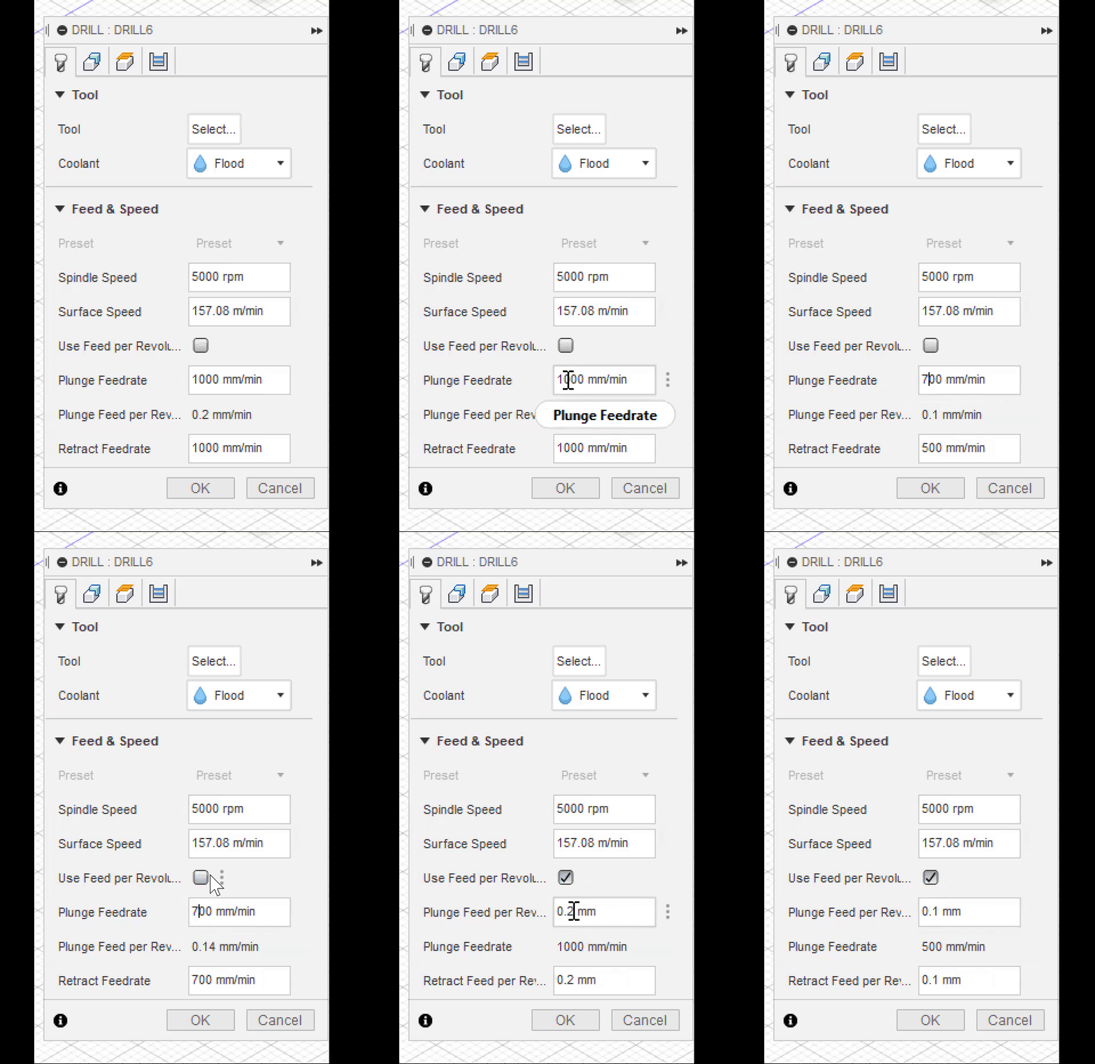
We have also brought back both the FPR & FPM fields in the Tool Library presets. This will allow you to visually see all 4 input fields: Plunge/Retract FPR & Plunge/Retract FPM. They will retain the old behavior of being linked together with one driving the other with changes. The ‘Use FPR’ checkbox will remain in the Tool Library preset and will act to default set the FPR checkbox on/off. The presets will pass both fields independently to the operation, and if you check/uncheck the ‘Use FPR’ we will take the value from the Preset when performing the initial switch.
Improved Geometry Selections
Back in January we released a big change in how you select geometry within the Manufacture Workspace. In this update you will see a series of enhancements to the Geometry Selection functionality:
- Pocket area preview will no longer block selections
- We fixed an issue relating to persistence of property expressions
- There will now be a warning when reusing selections from a different tool orientation
- We fixed an issue occurring while using mesh silhouettes
- We added support for handling expressions stored in templates
New and Improved Post Processors Update
Looking for the latest post processors and machines updates? This March we released a ton of new updates and improvements to many of the open-source Post Processors and Machines we offer for free. Within this release you will see a new beta post processor for FlexCNC as well as a new milling post processor for Faro CNC. In addition to that, you’ll find improvements to generic post processors, milling post processors, turning post processors, mill-turn Post processors, and additive post processors. We also added new machines to our machine library, updated our Haas tooling library and improved functionality around the Autodesk CAM Post Processor engine.
To learn more check out the forum post here.
API & Add-ins
New API calls for Manufacturing
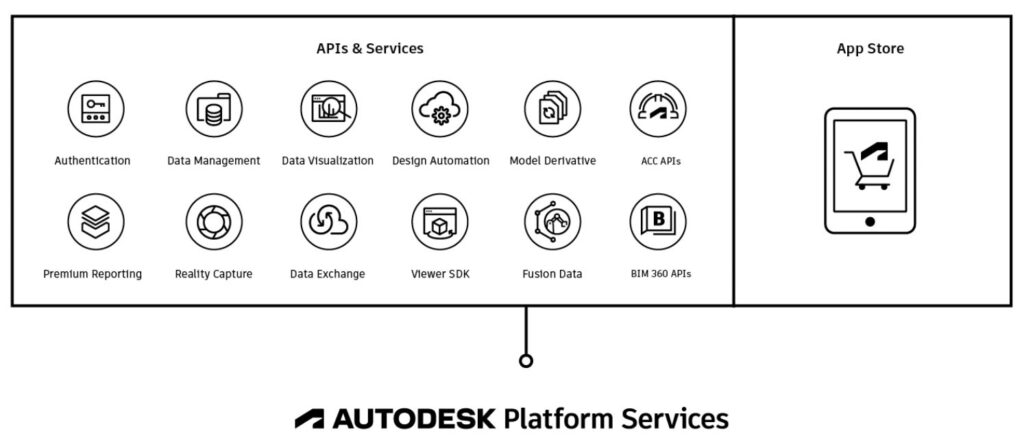
Big news for those of you who use Fusion 360 API, you can now create scripts (Python/C++) to:
- Create Manufacturing Setups
- Add operations
- Control (most of) the inputs / parameters to those operations
- Generate toolpaths, and post using the NC program
You will also be able to access the following libraries via the API to accomplish the above-mentioned points:
- Machine library
- Tool library
- Template library
- Print settings library
- Post library
Additionally, you will be able to choose items from an existing library and to some level even edit the item in the library via the API.
New Makersite Add-in gives you live Assembly Carbon & Cost Calculations
Makersite uses AI, data, and apps to power sustainable product and supply chain decisions at scale. This plugin provides a direct integration to the Makersite platform from within the Autodesk® Fusion 360™ environment. It works by converting your CAD model into a Bill of Materials (BOM), and requests Makersite to calculate climate change impacts as well as cost estimates of the BOM. It also provides suggestions on how to reduce these impacts in the form of material alternatives. Results can be visualized in a grid or as heatmaps. More, extensive information on other criteria such as risk, compliance etc. as well as more powerful scenario modeling, collaboration and PLM/PDM integration tools are available through subscriptions of the Makersite service.
Download the free trial and give it a try today.