
V.2.0.8816
3D Modeling
Jonathan0137 experienced a crash in his design when he tried to “Get all Latest” for his referenced designs in his assembly. This is now fixed.
Electronics Design
We fixed an issue where if you output a PCB design as a Gerber output and loaded the result in a Gerber viewer, some of the Poly Shapes went missing from the rows of footprint SMDs, and were instead output at the board origin.
A number of you have reported instability issues while working through some routing workflows. We tuned our engine under the hood and things should run more smoothly now.
Manufacture
Slickiii told us about a bug where every time he tried to create a thread turning tool, the tool is saved but says that it is missing required data, even though he had already entered them.
This bug has been squashed.
v.2.0.8809
Stability
We found some instability in how Fusion 360 handled uploading of certain assembly designs, and tweaked the engine so that it now runs smoother.
Drawings
Some of you have reported about a wonky behavior in the Drawings environment where if you were working with a table, clicking some cells would randomly select multiple cells all at once (as if you were pressing the SHIFT key). Sorry about that – we fixed this wonkiness in this update.
Electronics Design
There was a bug that was causing a Z-axis issue affecting PCB faces when you tried to render the PCB board with local or cloud rendering. We squashed this bug and resolved the issue.
Manufacture
We improved the speed at which patterns with many copies, and/or patterns involving heavy or many toolpaths appear when you try to select and edit them. It should feel faster now.
We also improved how Tool Renumbering works in the new tool library. Previously, tools are numbered in the order they get selected, and some that are not in use are still being numbered as if they were. Now when you select Renumber Tools, they will appear in the order they are used in a setup, so that looking in the CAM browser, the tool number is in descending order.
Additive
Apparently the FFF custom print settings, regardless of whether it was saved locally or in the cloud, were not being remembered by Fusion 360 and disappeared after you restarted it. Now they will be truly saved and remembered!
v.2.0.8749
[toc]
Sketching & Modeling
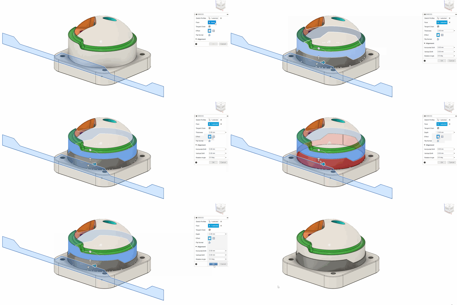
New! Emboss command
Design workspace > Solid Tab > Create Panel > Emboss
Now you can emboss like a boss, and abandon those pesky work-arounds that you were used to doing. The Emboss command now lets you select the sketch profile you want to use as well as the surface you want to emboss onto. Currently Emboss works with Sketch Text, but we are also in the process of revamping the Sketch Text command as a whole, which will give you more flexibility around working with text in the Sketch environment, and enabling text-on-path. Stay tuned for that.
New! Edit by Curve command
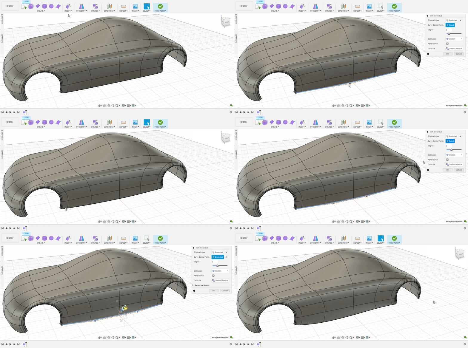
Design workspace > Solid Tab > Create Form > Modify Panel > Edit by Curve
You will now find the new Edit by Curve command right below Edit Form in the Create Form environment. Edit by Curve gives you more control and fine tuning abilities over a series of T-Spline edges by using Curve Control Points instead dragging on the actual edges like in Edit Form. You also get more options like Degree values, Distribution, Planar Curve toggle, as well as Curve Fit preferences.
Improved! MovingParting Line Draft
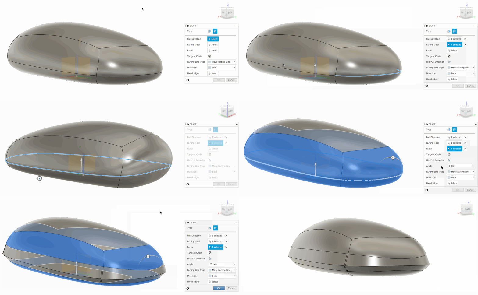
Design workspace > Solid Tab > Modify Panel > Draft > Move Parting Line

In the last update we introduced the ability to create a parting line in the Draft command. Now you can move a parting line by specifying a draft angle. You can also set the Direction to be Angle Above, Both, or Angle Below, as well as select Fixed Edges depending on your design.
Improved! Direct parameter naming within dimension creation
Create Sketch > Dimension > change the default dimension name
It took us a long time to get to this one, but we’re glad that we finally got it in. The idea of this improvement can be traced back all the way to 2014 via the IdeaStation, and it is now finally available in Fusion 360!
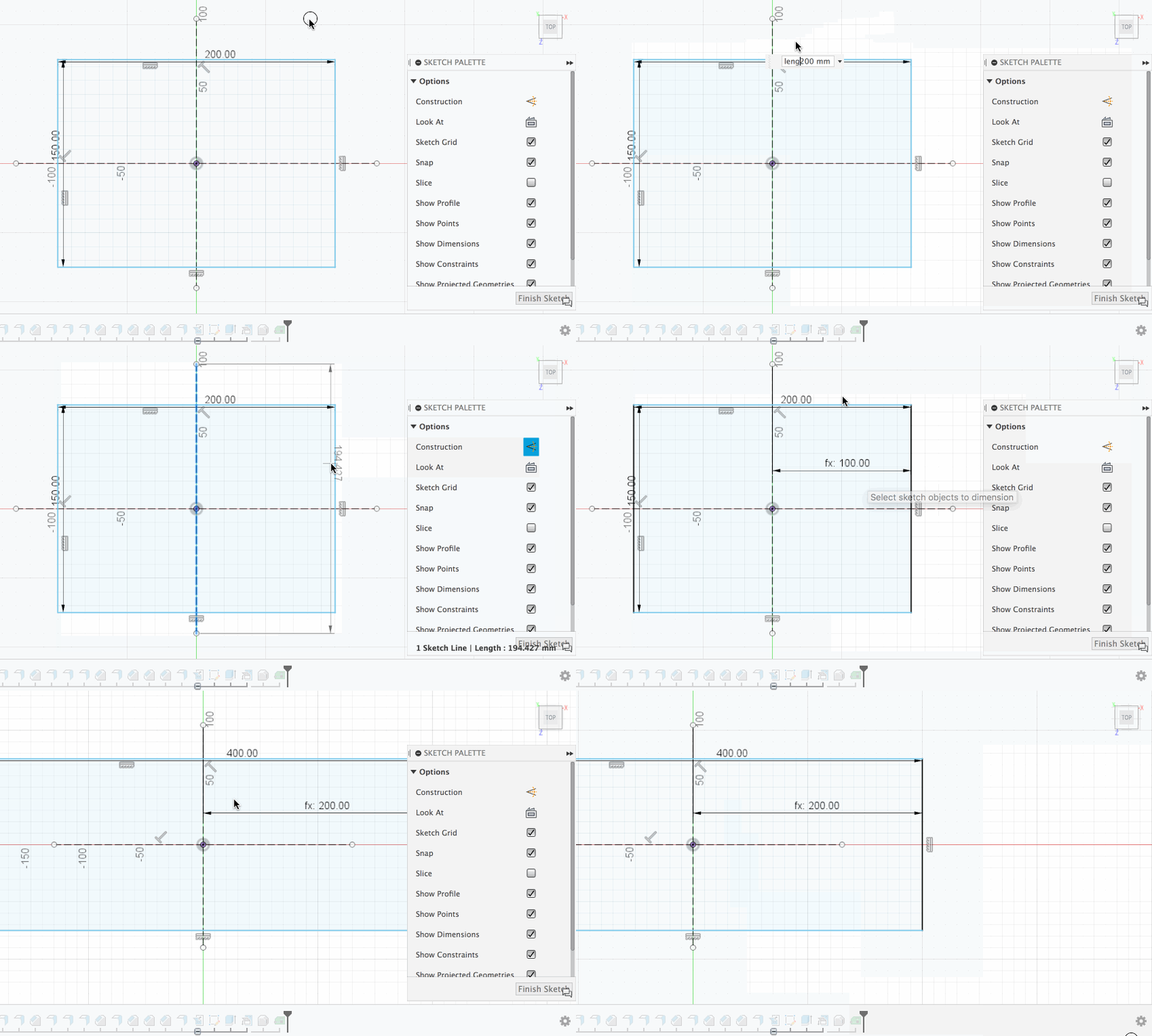
Now when you create a dimension on a sketch, you can change the name of the default dimension while entering the value. Just enter the name you want for that dimension and give it an equal sign. That dimension will be called that name from now on. No longer do you have to go to the Parameters dialog to change the names. You can also use the custom parameters in your modeling tools, such as Fillet, Extrude, Sweep, or any tool that lets you input a value.
Improved! Create New Component now has External and Internal options
Design Workspace > Create Panels > New Component
EIP made it possible for you to edit a referenced component in-place of the assembly that it is in, and now you can create a referenced component directly within the assembly you’re working in and have that component saved automatically to the location you choose.
The New Component command dialog now has 2 new options: External and Internal component Creation. Selecting Internal will create a new component like it has always been, but selecting External will create a referenced component within the active assembly, and reveal a new Location option, letting you pick where you want this new component to live.
[expand title=”See more”]
Once it’s created, you’ll be taken right into EIP mode.
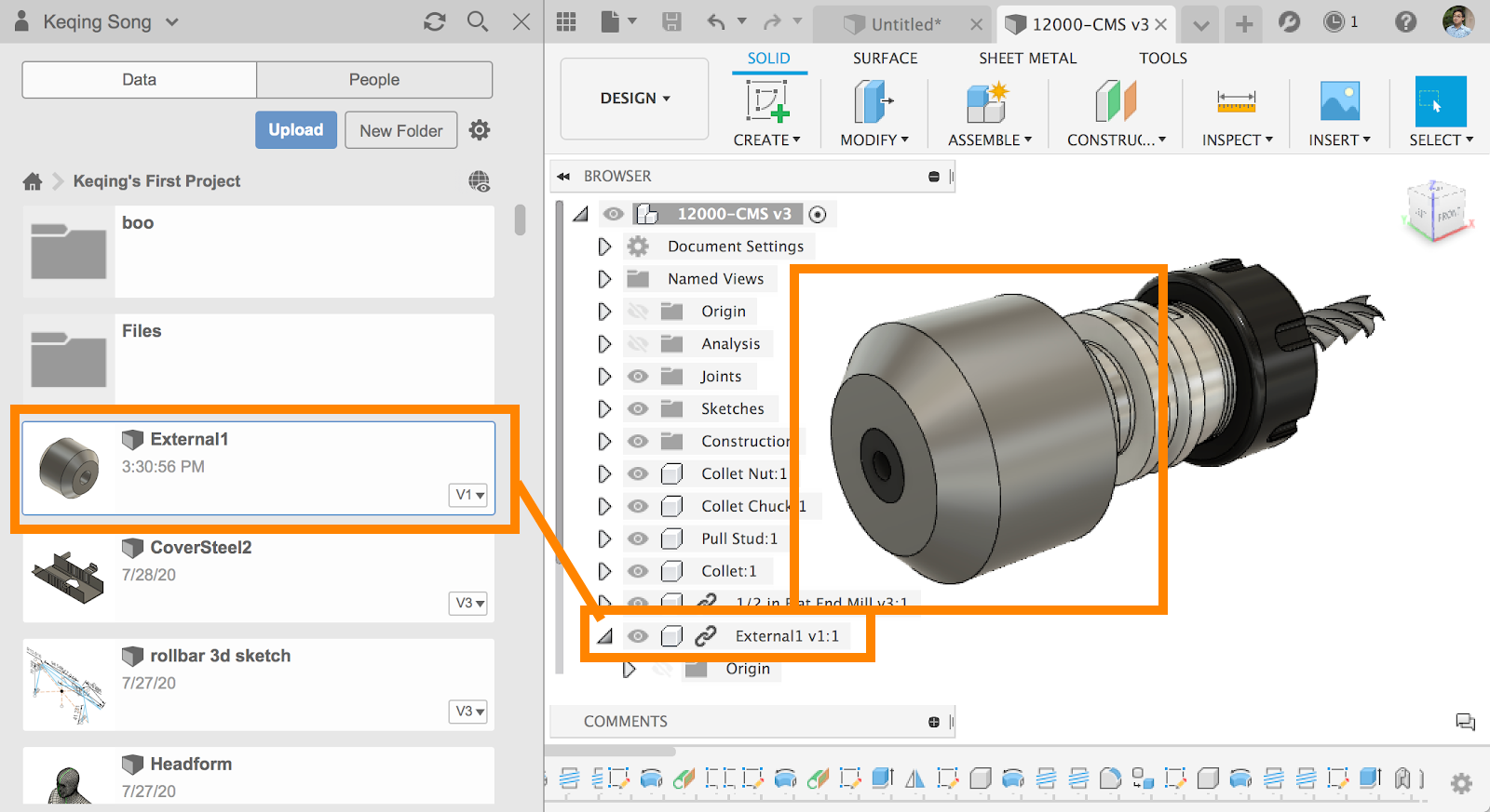
When you’re done with your edits and have saved the assembly design, you can see that the newly referenced component can be found in the project folder you selected earlier as a standalone part.
[/expand]
[expand title=”See Help Documentation”]
[/expand]
Improved! Assembly designs now open faster
File > Open
In past product updates, we improved joints performance when you moved components joined to other components in your assembly. In this update, we tweaked the algorithm that controls how you open your assemblies from the File > Open path and are seeing significant improvements in open speeds compared to previous times. Through our testing, we clocked some of the improved open speeds to be as high as 75% faster than before, using the same design as our control.
[expand title=”Other Fixes – click to expand”]
- FrodoLoggins and HughesTooling showed us a wonky issue regarding the Measure tool and how it was grabbing measurements out in the middle of nowhere. Sorry about that; based on the examples you provided us, we were able to fix this issue!
- We improved a Press-Pull/Offset behavior that has been a pain-point from a number of you. If you invoked Press-Pull and entered a value instead of using the arrow manipulator, invoking the command again and using the arrow to press-pull sometimes caused Fusion 360 to crash. Turns out Fusion 360 remembered the value you entered the first time, and thought you wanted to use that value for new subsequent Press-Pulls. We fixed this and now it will forget it.
- DimaGorbenko had a couple of issues with copying a body from one design and doing a “Paste New” into another one that contained custom parameters. Apparently, the custom parameter values are honored with the paste, but the parameter name is incorrectly renamed with an extra “1” attached to the name. Furthermore, trying to rename the parameter back to the original generated an error message. We fixed the renaming error, but are still working on the extra “1” issue.
[/expand]
Electronics Design
New! Edit in Place for Electronics
Design > Insert > 3DPCB > Edit in Place
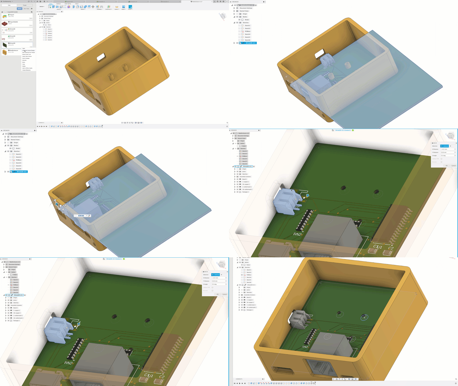
One of the most common challenges between the electronic and mechanical engineer is communicating the exact placement of components that will require external access. These typically entail adding an USB component or maybe exposing a LED for power indicators, or even an on/off switch. This will require many emails and calls between the multiple disciplines of engineering to get it right. With EIP support for 3D PCBs, you now have the flexibility to quickly update components right in the context of the assembly design workspace.
New parts added to library
File > New Electronics Design > New Schematic > Add part
This update includes new parts in IC_Embedded library from Atmel AVR micro-controller series MEGA16, 32, 64, 1280, 1281, 2560, 2561, 644. We also also added a couple of Boost (Step-up) voltage converter IC’s in IC_Power-Management library.
Improved! Ratsnest behavior
PCB Editor > Move
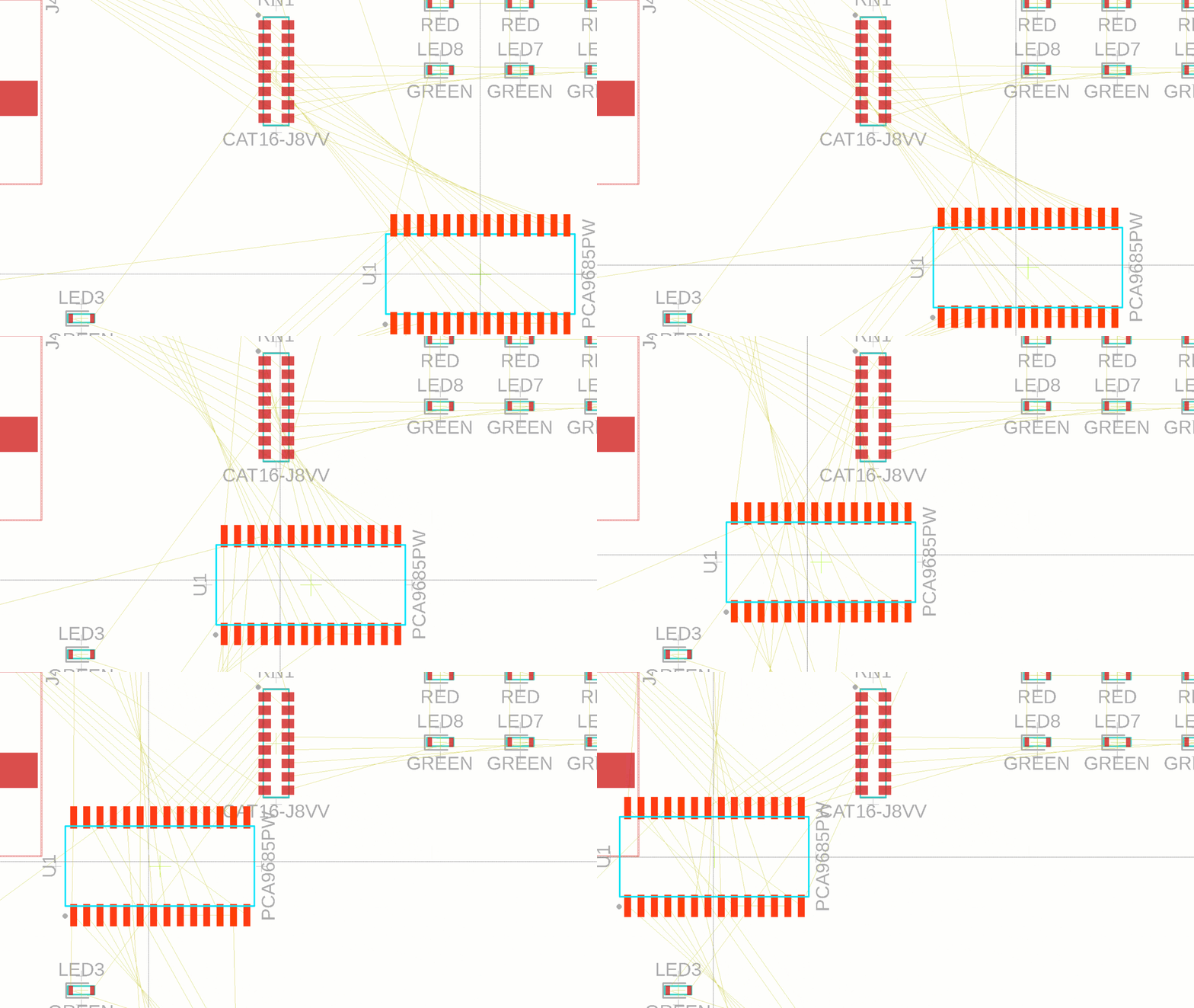
We made changes to the design workspace that are truly innovative and unique to Fusion 360. Traditionally, the Ratsnest command required to be manually invoked to recalculate the shortest possible path of a signal. With the latest release this action is now performed interactively. As you move your components you will notice your signal connection looking for the closest path.
Improved! Push & Shove behavior for moving components
PCB Editor > Move > Push & Shove
It is unavoidable that changes will need to be done to your design. There will be instances that new components will need to be added or changed to your design. Traditionally these changes required moving or deleting of existing traces to make space for the new assets. Rendering all the efforts you spent routing a waste of time.
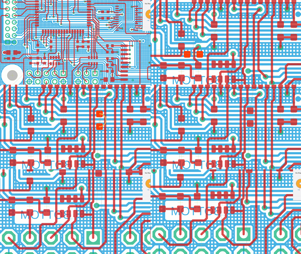
Now in Fusion 360, obstacle handling is no longer restricted to the routing commands. This is now a PCB-editor capability available in all appropriate commands. As such, the options for what to do when a violation occurs is now on the Navigation Toolbar rather than the route command panels since it is now an editor setting. With the push violator option enabled, traces and vias will move out of the way to accommodate the placement of un-routed components. We think this will greatly optimize your design time.
Improved! Tighter Library.io Integration
The electronics library now has a tighter integration with library.io, allowing you to access almost 8000 available 3D Models.The comparison above shows what used to be on the left, and the new improvements on the right. New icons in the toolbar will enable you to link your library to it, and fetch real-time updates as you edit your design. It is now aware of changes made to linked managed libraries and will guide you as you merge the changes. Detailed tooltips will appear upon hovering over a library.io component. Selecting that component will reveal a direct link to library.io on the web, so you can manage your content there as well.
Improved! Support Gerber Output For fixed and proportional True Type Fonts
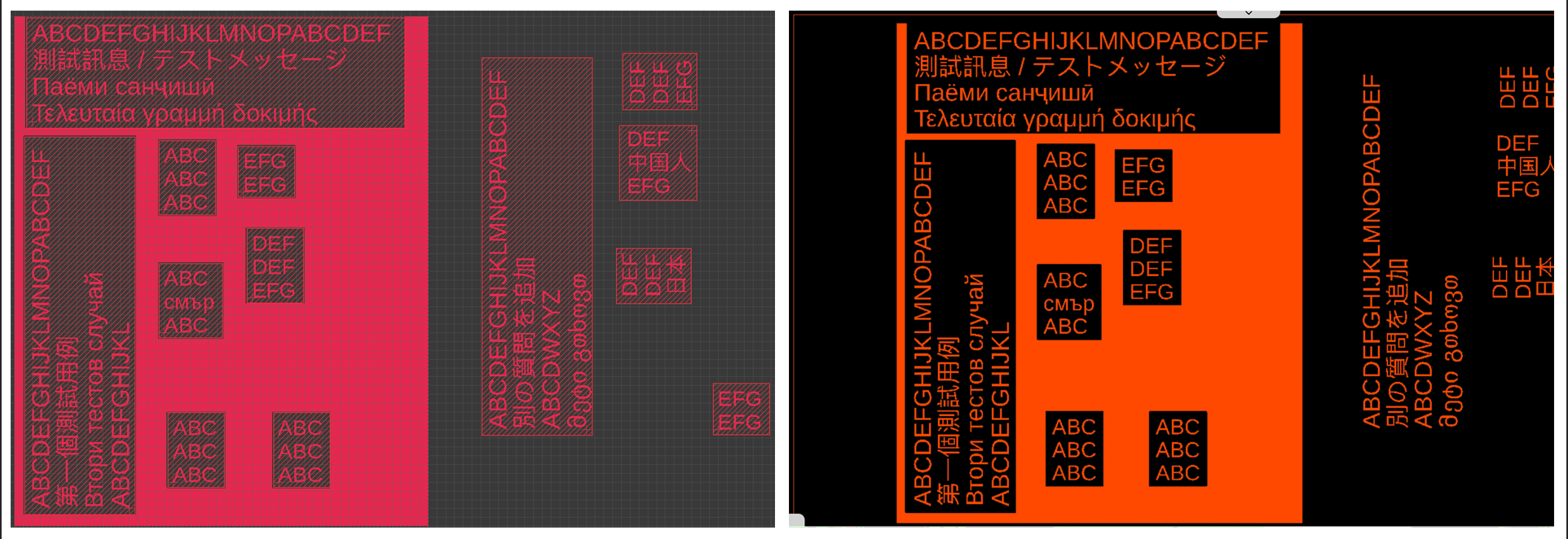
Left: TTF in Fusion 360 Electronics Design | Right: Text in Gerber output viewer
If you were coming from Eagle, you were aware that it only supported Gerber output for vector font type. If you used a fixed or proportional True Type font, it would get converted to a vector font at time of Gerber output, which resulted in discrepancies between the manufactured boards and what you (the designer) saw on the screen. Now we’ve enabled Gerber output to support fixed and proportional True Type fonts without converting it to a vector font. This insures that the font you used in the board design for any text objects will match exactly what will be generated as Gerber output (What You See Is What You Get).
Rendering
Improved! Instructions for Render on Save
Render workspace > Rendering Gallery > Render On Save
Some of you may not be aware that when you create a local(background) rendering or cloud rendering, you can drag that specific rendered view and drop it to the left space where it says “Render on Save” within the Rendering Gallery. This will automatically kick off a re-render of that view every time you commit a save on that design, making it easier for you to keep the views you’ve spent so long to set up.
Previous drag-and-drop instructions made it sound like you can only use your named views; we’ve made the instructions more clear, specifying that the thumbnail views are the ones you can drag and drop.
Drawings
New! Section View Depth Control
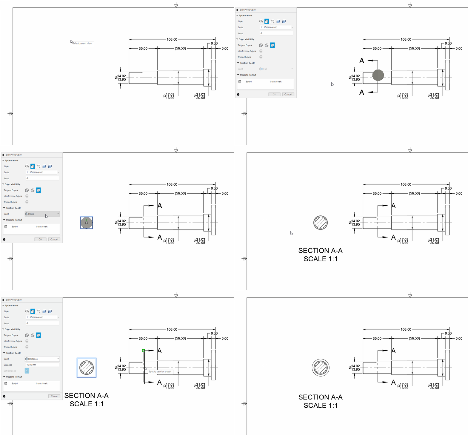
We’ve leveled-up our Section View command to give you control over your section depth in cases where you want to reduce the appearance of unwanted geometry. Rather than cutting through the full part, you’ll have the option to choose a zero-depth ‘Slice’ or select a ‘Distance’ via an input or slider in order to define the desired extent of the cross-section.
Improved! Image Insert from the Cloud
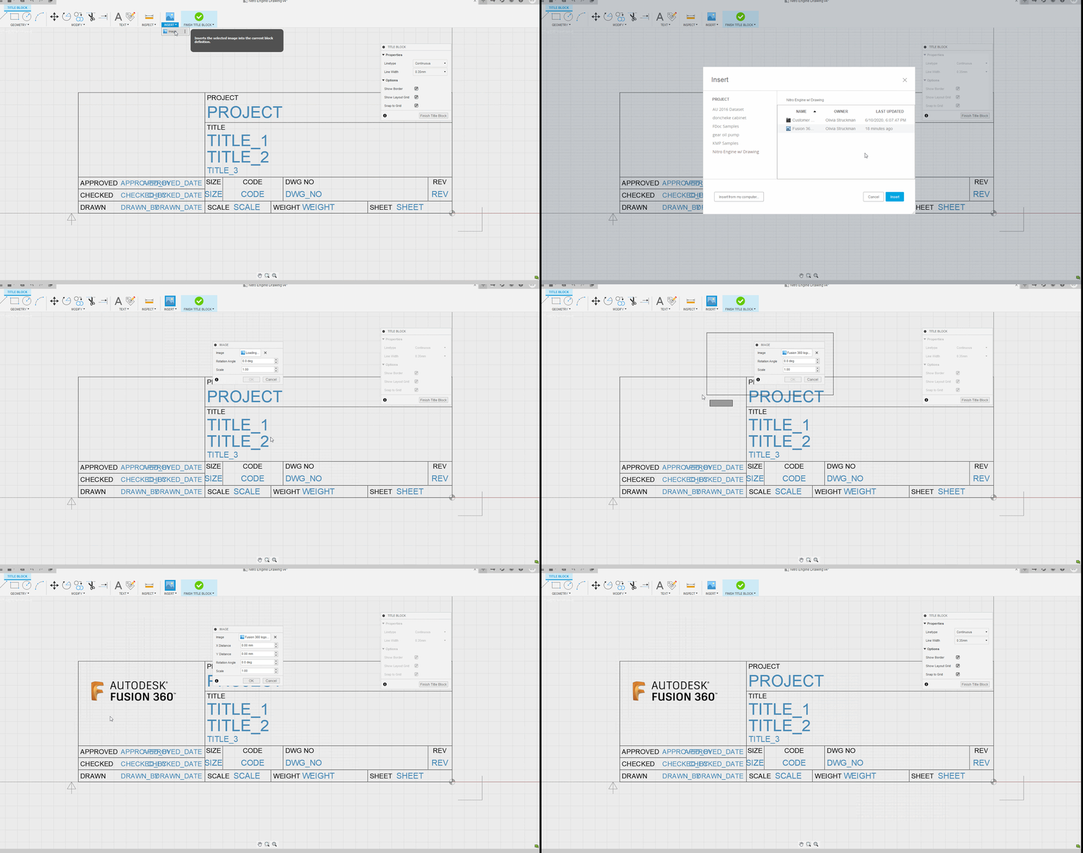
You can now insert your company logo to your title-block, or add other images to your drawings, by selecting the image file you’ve uploaded to your project. Similarly to how you might insert a decal into your model, you now have the option to insert images from both your cloud project and local computer. Uploading your images, logos and decals to your project ensures that your data stays together and is always accessible from the same place.
Improved! Drawing support for French and Italian
French and Italian speakers rejoice! Following the recent additions of our 2 new languages in Fusion 360, the drawings environment now also supports both French and Italian. Thank you for your patience on this one; localizing something as complex as Fusion 360 does take some time, but we’re glad this is now available.
[expand title=”Other Fixes – click to expand”]
- We’ve addressed the underlying issues causing crashes upon Drawing creation reported by ondrej.valach on the forums. This should be cleaned up now for those of you hitting this snag.
- Shawn.parella alerted us to a slow-down in detail view placements – we’ve made some changes so detail view generation and placement shouldn’t slow you down any longer.
- You reported a few problems with editable (also known as “empty”) tables in the latest release. Some of you noted that your edit would “just stop”; others noticed that selecting a single cell sometimes selected a whole bunch of cells! We’ve got those fixed up.
- jonasZUZ5J and others alerted us to issues encountered when inserting images with filenames that included “non-English” characters like ü, ß, and Å. We were tripping over these characters. We’ve fixed that, so you’re free to name your images as you wish.
- Previously, the “All Around” option for Feature Control Frames in the German UI failed to create a circle as expected. This is fixed now for our German-speaking users.
- We heard your reports of symbols and text, added to dimensions, sometimes being removed on drawing open; oops. What we found was this could happen if your text was inserted inside the angle brackets. Say your dimension looks like this, and you added the Ø and mm to it.
When you double click to edit you see this:
Text inside the angle brackets is updated by the software; for example, if a distance in your model changes, we update the dimension value. We fixed the problem of removing these characters, but in the future, your best bet is to add your text outside of the angle brackets, like this:
As for displaying units on your dimensions there is a drawing-wide setting for this, so you shouldn’t have to add these yourself.
[/expand]
Simulation
Improved! Heat Sink Idealization supports multiple bodies
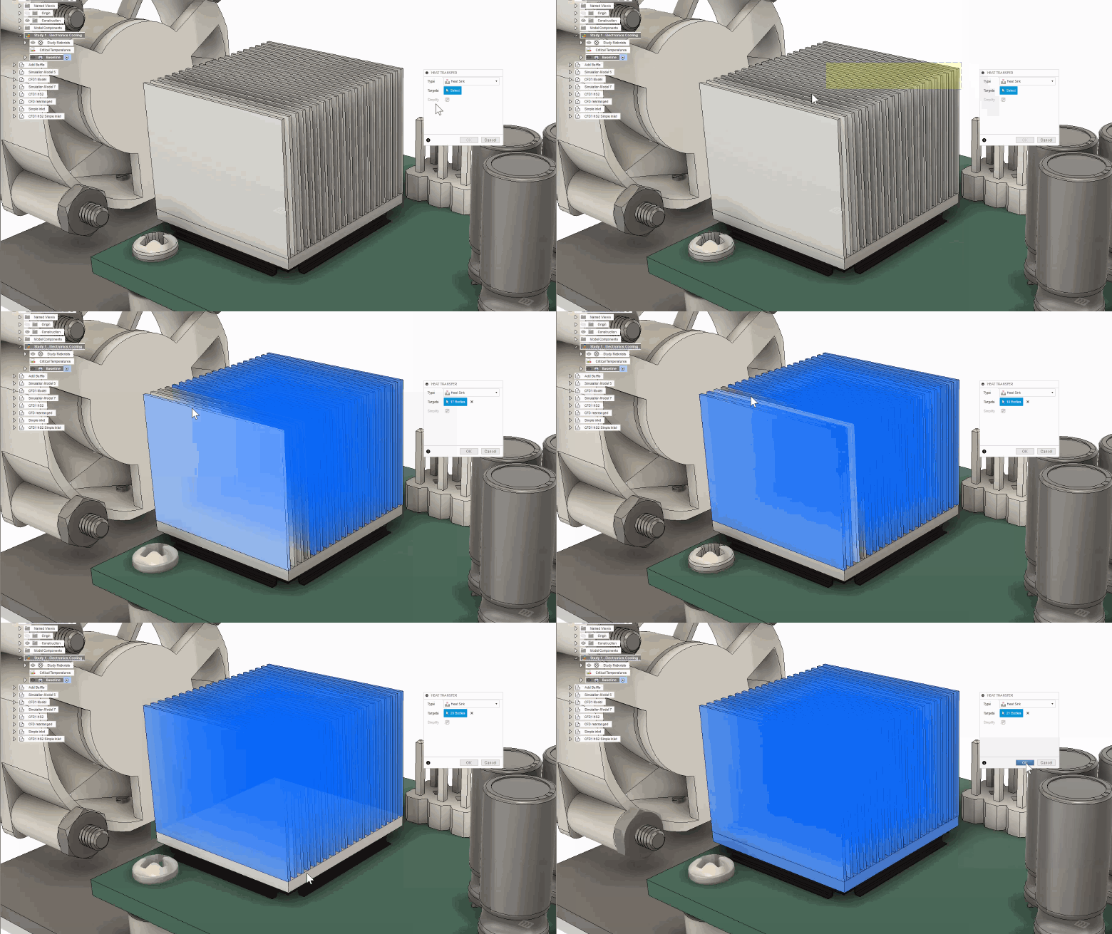
In the last update, we introduced a heat sink idealization capability. Heat sink idealization allows for an accurate, fast-solve when fine detailed heat sinks are used in the assembly. One of the limitations was the heat sink had to be a single body. Now you can select a collection of bodies as the heat sink. This is useful for geometry where the fins might be separate bodies in the CAD model. Why is this important? Because it allows for a quick designation and ability to use multi-body heat sinks with thin fins and gaps like the one below without having to edit the geometry.
New! Event Simulation: Element Deletion Criteria
Simulation workspace > Event Simulation > Manage > Element Deletion Criteria
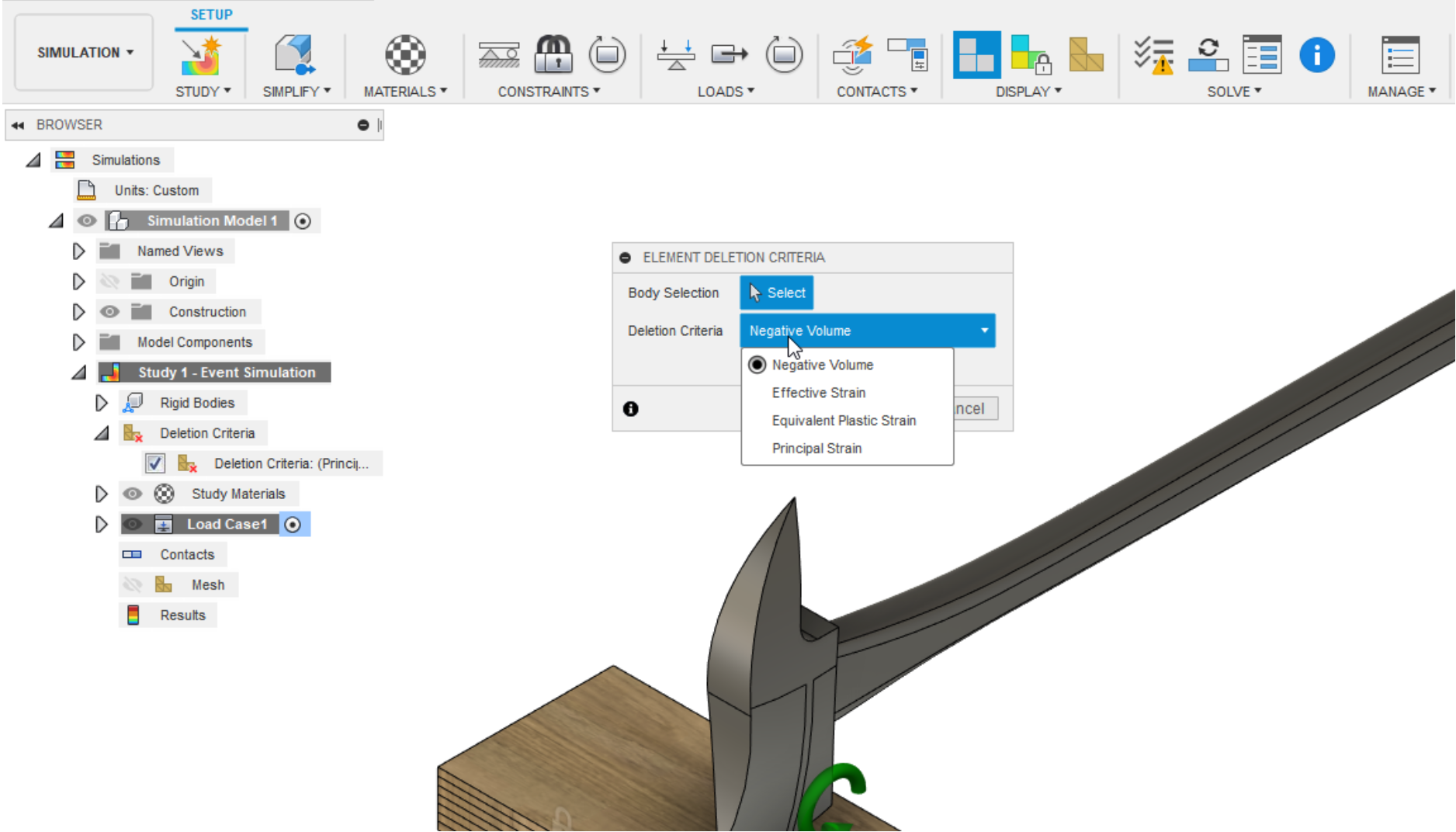
Previously, in Event Simulation, the Allow Element Deletion option in settings would add deletion criteria of NEGVOLUME and EFFSTRAIN to all parts of the model which might not be needed for the user. With the latest update, we have added Element Deletion Criteria as a separate dialog which will allow the user to specify the bodies to which the Element Deletion Criteria should be applied. We have also added additional choices in the Deletion Criteria which now allows the user to choose between Negative Volume, Effective Strain, Equivalent Plastic Strain and Principal Strain.
New! Event Simulation: Explicit Results Output
Simulation workspace > Event Simulation > Manage > Settings > Result Output
We have added Plastic Strain, Contact Forces and Applied Loads as additional Result Output options for Event Simulation Study. If these are checked, they will be available as separate results after the simulation has completed.
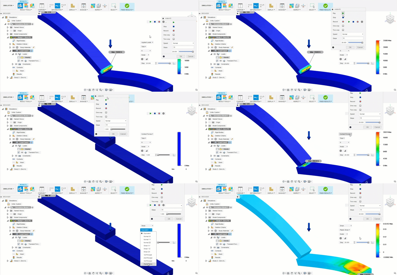
New! Point Masses in Explicit Studies
Simulation workspace > Event Simulation > Loads > Point Mass
Point Mass loads are now available for Event Simulation Study. To represent the weight of non-critical model bodies or components, substitute Point Mass (Auto) loads. To represent loads associated with items that are not a part of the model, apply Point Mass (Manual) loads.
Improved! Event Simulation: Error code Cause and Action
Simulation workspace > Event Simulation > Solve > Solve Details
If the Event Simulation Study fails to solve due to a solver error, we now include the Cause of the error as well as an Action that could help the user resolve the error and run their simulation successfully.
Manufacture
New! Arrange for Nesting now available as Preview Feature
To try this, go to your preferences > Preview Features and turn on Arrange Feature as well as Manufacturing Working Model
A brand-new feature called “Arrange” is now available as preview functionality for you to try. We talked about this as part of our nesting workflow in our roadmap update in June; it enables efficient object arrangement within a specified rectangular or non-rectangular bounding area.
With Arrange, you can specify either a plane or a sketch as the arrangement boundary. While the orientation of selected bodies is auto-detected based on the largest area planar face, you can flip the objects or select an alternate face interactively. Similarly, you can also create the arrangement above or below the chosen planar boundary. The arrangement results can be updated associatively with any design and/or bounding area changes. Additionally, the results get saved to the timeline allowing changes to replay in sequence as the history marker is moved backwards or forwards.
New! Toolpath Template Library now available as Preview Feature
To try this, go to your preferences > Preview Features and turn on Template Library
The toolpath Template Library allows you to save your favorite toolpaths and recall them for other machining projects. You have the ability to save a single operation, selected individual operations, or all the operations from a Setup.
New! Isolate context menu option
Manufacture Workspace > Browser > Right-click > Isolate
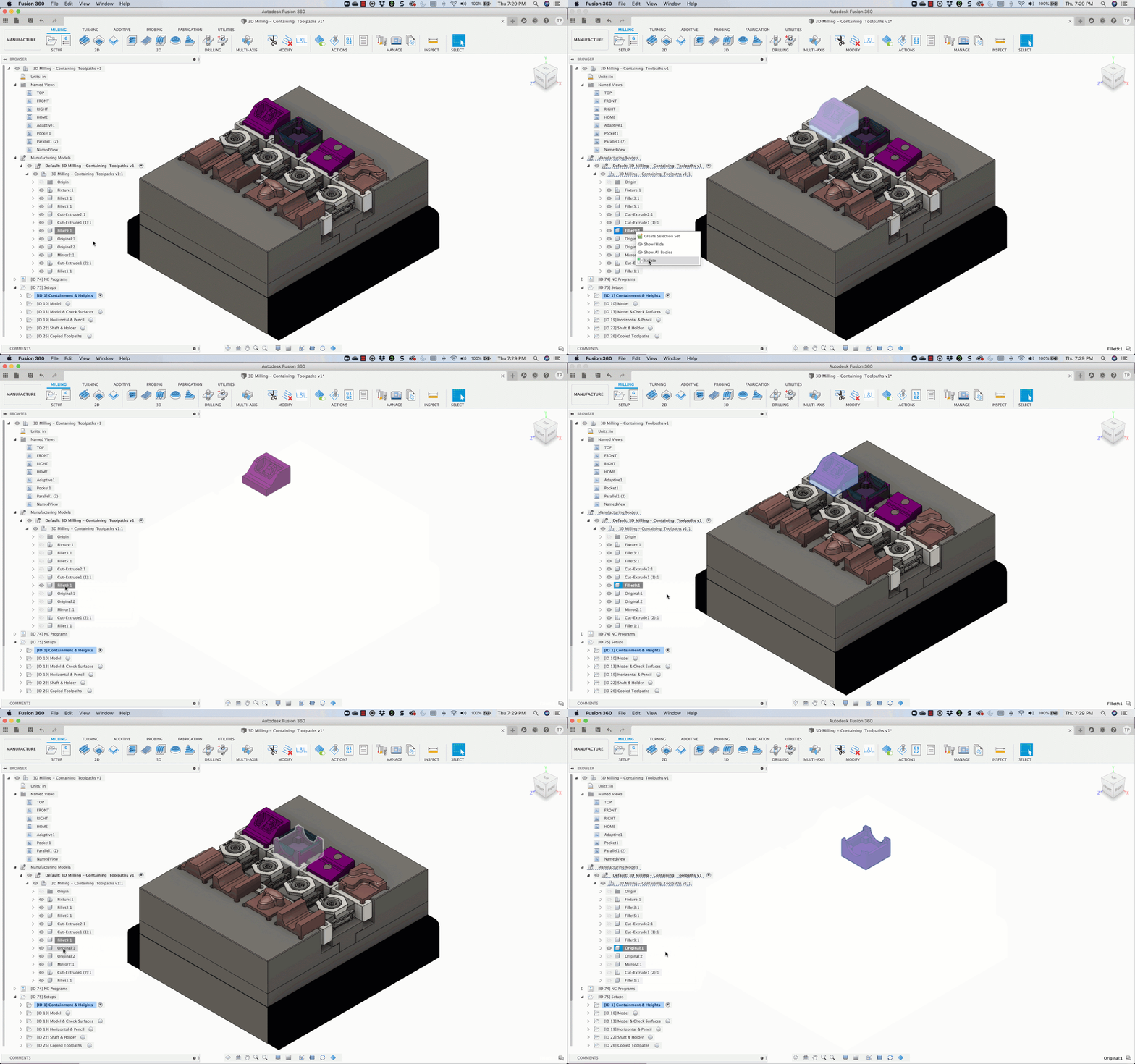
If you’re working with multiple bodies or multiple components in the design space you’ve probably come to love the isolate tool as much as we have. Now you can quickly isolate what you are working on in the Manufacturing space.
Improved! Turning – Profile Roughing
We’ve made 3 major improvements to profile roughing workflows for Turning:
Even Depth of Cut, Eliminate First Shallow Pass, and Extend to Stock Parameter.
[expand title=”learn more”]
Profile Roughing: Even Depths of Cut
Previously this parameter was only available when the cycle was set to either horizontal or vertical passes. For the August update this parameter was added for the back-cutting cycle as well. When this parameter is checked, the roughing depths of cut are calculated such that they have an even thickness within each machining region.
Profile Roughing: Eliminate First Shallow Pass
Prior to this update, the depth of the first machining cut in a profile roughing operation used to be shallower than for the rest of the cutting passes since the first cut was measured from the z or x clearance from the stock limit, depending on the cycle. This has been fixed in the August update and now the first cut will be measured from the stock limit and equal to the subsequent depths of cut thus creating chips of even thickness.
Profile Roughing: “Extend to Stock” Parameter
This is now accessible in the Passes tab. When this parameter is checked (current behavior), this retains stock to leave only on the model. However, in certain scenarios this was causing a slight dip in the toolpath as it came off a shoulder on the model. When this parameter is unchecked, stock to leave is now left both on the model as well as the stock, which eliminates this unwanted dip.
Note: When the “Use Canned Cycles” parameter is turned on, this parameter is hidden and the toolpath is generated as though it was checked on.

[/expand]
Improved! Probe position now draggable for X/Y Wall
Whether you are using Probe WCS for part setting, or Probe Geometry for verification, vertical walls are some of the most commonly used geometry for probing . You can now control the position of the probed point by dragging- simply select the point at the tip of the probing arrow and move to the desired position.
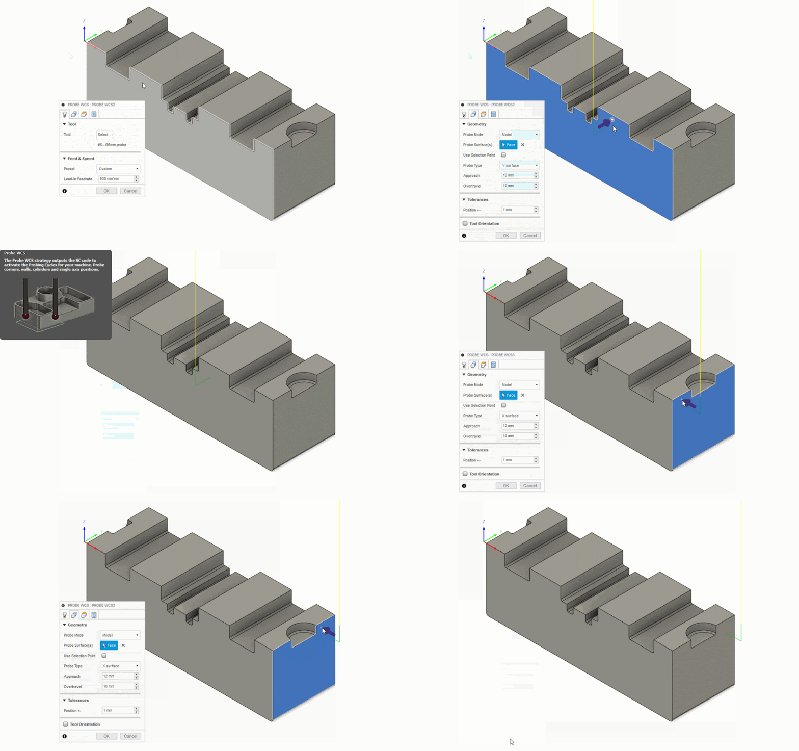
Select the point at the tip of the arrow
See Help Documentation about Probe WCS
See Help documentation about Probe Geometry
[expand title=”Other Fixes – Click to Expand”]
- In probing workflows, the folder that contained the probing results used to be called “Measure” in the browser. This caused confusion to some, so we renamed it to what it is: “Inspection Results”.
- 2D pockets: We’ve done a ton of work recently to improve some of the inconsistencies you’ve reported with 2D pockets, such selections not being detected and scenarios resulting in empty toolpaths. Most of the improvements you’ll see with face selected pockets and intricate and open pockets.
- In threading operations, we removed the “Use Constant Surface Speed” option since it did not apply and when checked by mistake, gave incorrect NC code.
- Rest Machining: Previously, if a turning operation had rest machining checked but there was a suppressed turning operation or an unsuppressed milling operation right before it, it ignored every other turning operation before it. This behavior was fixed so that a turning rest machining operation will now consider every other relevant turning operation before it while calculating the toolpath.
- There was a bug that prevented In-process stock (IPS) from showing when you clicked on the toolpath setup if “Continue Rest Machining” was enabled for that setup. Now it’ll show correctly.
- Roger__W reported an issue where he got an error saying “Cannot use canned cycle with the selected tool orientation and machining direction” when he tried to use the canned cycle option for his lathe roughing workflow. Sorry about that! We got this fixed now.
- We fixed a bug where the rest machining area was incorrect if a rest machining tool diameter of exactly 3.0 mm is used (any odd integer would previously cause an issue, but the error was less noticeable for larger values).
- We also sorted out an issue where certain turning profile finishing toolpaths were not generating correctly when a negative stock to leave was specified.
[/expand]
API
New! [expand title=”ActiveSelectionEvent”]
The active selection is the set of entities that are selected when the Select command is running. The Select command is the default command that automatically runs when no other command is running. When you press Escape to cancel the currently running command, the current command is terminated and the Select command is started. While the select command is running, the user can select entities which changes the active selection. The new even is fired when the contents of the active selection changes in any way.
[/expand]
New! [expand title=”CustomGraphicsShowThroughColorEffect color effect”]
This allows you to specify a single color for an object and also define that it will show through other objects. This means the colored object will always be visible, even when it is covered by other objects. The user manual topic on custom graphics has been updated with more information.
[/expand]
Improved! [expand title=”Minimal support for FlangeFeature, RefoldFeature, and UnfoldFeature“]
Minimal support means there are now API object that represent these features. Each one of them has an associated collection in the Features collection which allows you to find them in a design. If you’re scanning the timeline and get the associated entity from a timeline object, it will now return one of these features. The features support all of the functionality that the base class for all features supports; get and set the name, delete, suppress, get all of the faces that were created by that feature, get the associated timeline object. get the body modified by the feature, use attributes, and get the current health state, Creation and edit (besides the functionality list above) is not currently supported.
[/expand]
[expand title=”Other Fixes – Click to Expand”]
- The “Remove” option that was available in the context menu in the Scripts and Add-Ins dialog has been…removed. This functionality has led to a lot of confusion and frustration for everyone. Some of you thought that it would uninstall the script or add-in but instead it just flagged the script or add-in so it would not be displayed in the dialog. There wasn’t a way to find out what scripts or add-ins were being hidden and turn them back on. The primary problem was when someone had “removed” and add-in and then tried to install a new version. The new version wasn’t displayed in the dialog because the flag to hide it was still there.
- The ability to delete command inputs is now supported.
- The latest version of the CHM API help is now available with the online help. Look for the link in the Welcome page.
- VS Code was timing out while debugging. This has been fixed.
- The list of tabs returned by a workspace was not correct. This has been fixed and the sample to write out the user interface has been updated to better support the new tabbed user interface.
- kandennti reported a problem on the forum where the NurbsCurve3D.extract method didn’t work. It should work as expected now.
- The texture coordinate related functionality on a triangle mesh now returns correct texture coordinates.
- TheToolbarControls.addSplitButton was not functioning correctly and has now been fixed.
- OceanHydroAU reported a problem on the forum where pressing the tab key on a float slider would crash Fusion 360. It will now work as expected.
[/expand]
See Full list of what’s new on our Help Documentation