
V2.0.10811
Usability
New! Flat Shaded Option in right click for mesh bodies
Right click on mesh body in browser > Flat Shaded
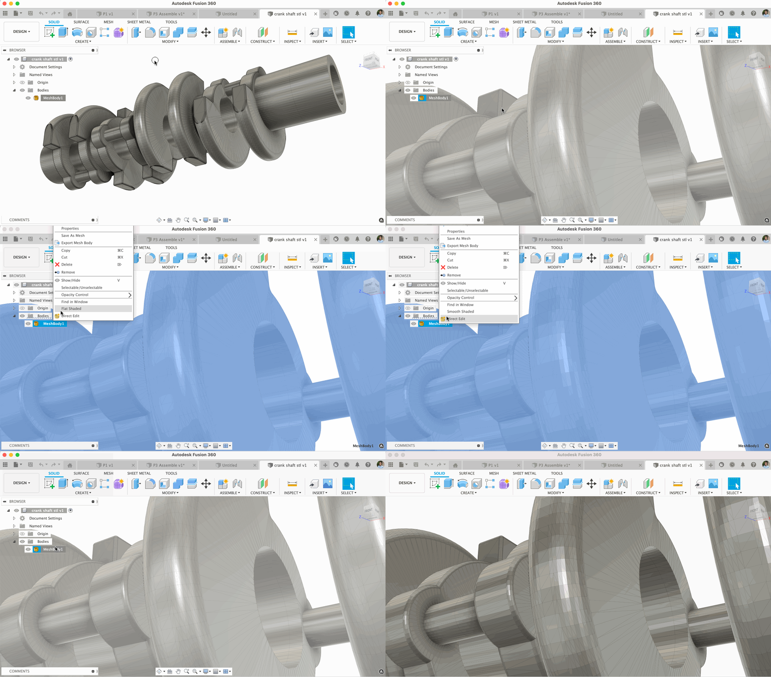
Sometimes you’ll want to see your mesh models in a “Flat” shaded visual style (instead of smooth). This allows you to better differentiate the number of faces on a body. Now when you right-click on the mesh body in your browser, you’ll have the option to select “Flat shaded” to do just that.
Improved! Visibility Overrides for sketches, bodies, and construction geometry in distributed designs
Browser > click the visibility icon next to objects within external components
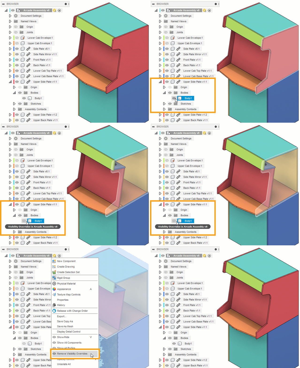
With more and more teams working with distributed designs, we’ve made it easier for you to override the visibility of objects within external components in the context of an assembly. Now, in addition to showing or hiding entire external components, you can also override the visibility of sketches, bodies, and construction geometry in the context of the assembly directly from the active design. You can also override visibility in the context of the assembly during Edit In Place, without affecting the visibility in the external design itself.
Learn more about Visibility Overrides
Sketching & Modeling
New! Analysis tab in Surface and Solid Loft command
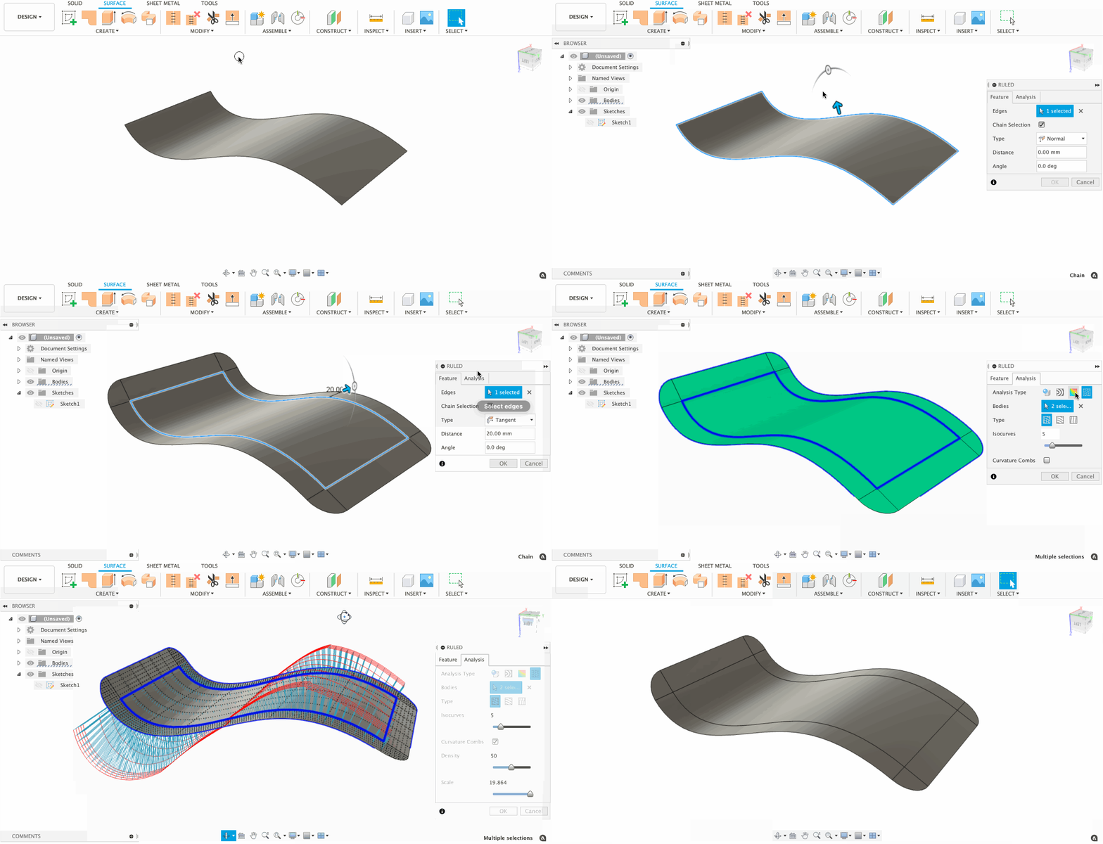
Expanding on the list of modeling commands that now include an Analysis tab, Solid Loft and Surface Loft now has an Analysis tab right next to the Feature tab within their respective command dialogs. This enables you to quickly examine your surfaces without the need to invoke an additional analysis tool.
Learn more about surface analysis during Solid > Loft.
Learn more about surface analysis during Surface > Loft.
Improved! General Modeling Performance
We tweaked our modeling engine and are happy to report that we have improved general compute performance of mid to heavy-weight modeling commands. For example, performing a complex 50×50 model patterning task was initially tested to take around 15 minutes to compute. Now it only takes 3 minutes.
Improved! Sketch Profile Builder Performance
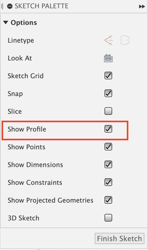
In Sketch Palette , we have an option to ‘Show Profile’ (shown below) which builds/creates the profile in sketch. Once profile is created, we can see the profiles created on hover over the sketch. Previously, Fusion 360 took a long time to build the profiles. We’ve improved the sketch engine and boosted the speed of which the profiles are built. You should be seeing some significant performance gains now.
Electronics
New! CAM Processor export ODB++
File > New Electronic Design > New PCB

Congratulations, you finally completed your PCB design, and it is time the generate your manufacturing files. Traditionally, you would be accessing the CAM Preview to get a realistic preview of your design then move on to the CAM Processor. While accessing the CAM processor, you will be pleasantly surprised with the new ODB++ section. ODB++ is a manufacturing-oriented PCB product model data format, having all the necessary data for fabrication, assembly, and test in a single file structure. ODB++ is the most widely used intelligent data exchange format in the PCB industry, making it the de facto standard for intelligent PCB data exchange.
New! Export to Ansys
File > New Electronic Design > New PCB
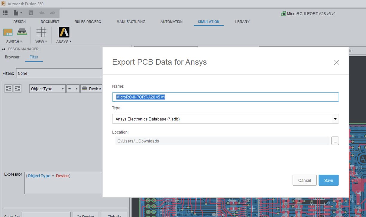
Next time you are editing your PCB, you are going to notice a new simulation tab. The toolbar includes a new entry option to export ANSYS files. This option now empowers Fusion 360 to export Ansys file and gives you the choice to launch Ansys desktop if installed.
By exporting Fusion 360 Electronics Design with Ansys SIwave (and Electronics Desktop) for electronics designers and engineers will make electromagnetic simulation easy, powerful, and accessible, leading to reduction in design cycle time and increased profit for electronics designers as they reduce prototyping and certification (FCC/CE) costs.
New! Preserve angle in Schematic
File > New Electronic Design > New Schematic
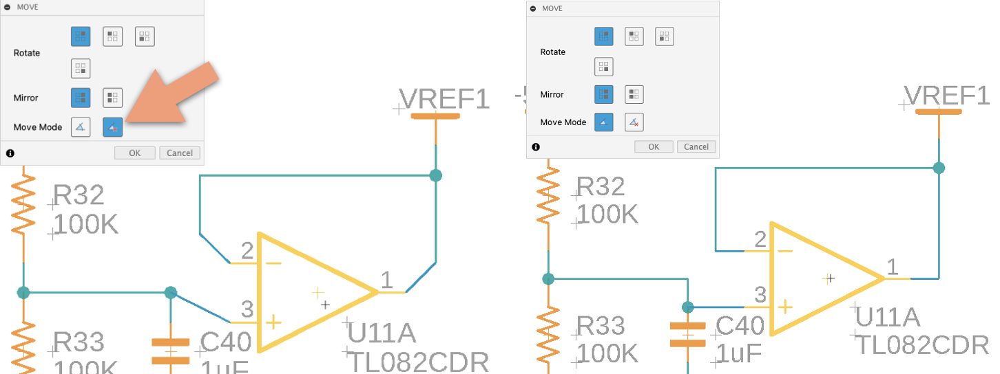
While putting together the schematic for your next innovation, there is a good chance you will need to strategically reposition components. Traditionally moving components on the schematic editor would cause the connection to move into undesirable angles. Fusion 360 schematic editor has now adopted the option to preserve angles as it does on the PCB editor. Next time you move that capacitor or inductor, the nets will preserve their direction. This should help with your design time since you no longer must spend time trying to straighten your NETs.
New! Male Pin Header Package Generator
File > New Electronic Library > Create New Package
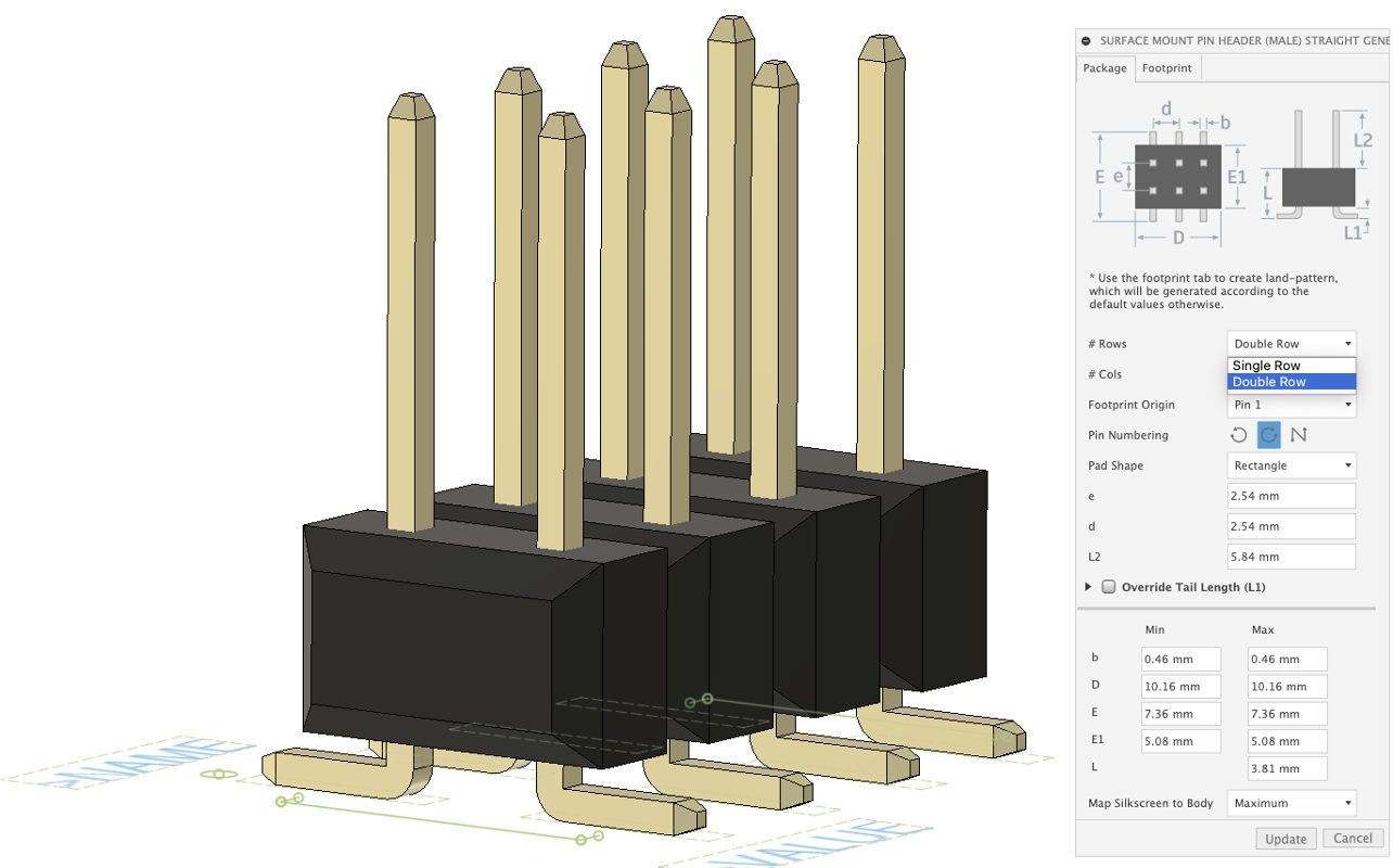
The foundation of all electronics design is based on the component libraries. Fusion 360 has partnered up with manufacturers and distributors to provide you with a host of components ready to be used on your next design. But there will be times making your components will be necessary. Fusion 360 library editor does include a simple interface with all the necessary features to create your part in a matter of moments. The library editor consists of a package editor that includes the majority of IPC component templates and much more.
We have added a new package type for Surface Mount Male header (straight) which supports single & dual row along with customized footprint (non-ipc derived). This type is an alternate to the through hole pin header especially when there is a specific design requirement for SMD components on PC board. They are generally used to connect PC board-board without a cable (by mating with a receptacle connector) thus allowing design flexibility for assembly without any soldering.
NEW! Use 2D PCB Grid option for editing 3D model
File > New Electronic Design > New PCB

The process of placing components on the PCB in the correct pattern is critical when laying out a circuit board closely followed by routing your signals. Both these processes are dependent on the grid being used on PCB. Commonly there will be two grids setup: one of them will be viewable, while the second grid is referred to as the alternate grid.
With this grid combination, the PCB Layout engineer needs to be able to balance component placement with signal routing that meets the design requirements. For today’s high-density complex designs, this can be a big challenge. In this Fusion 360 update, our team of developers has been able to give you a unified design experience by adding the option to use the PCB grid in the PCB 3D modeling workspace while moving assets.
NEW! Display Vias and Pads with layer colors
File > New Electronic Design > New PCB

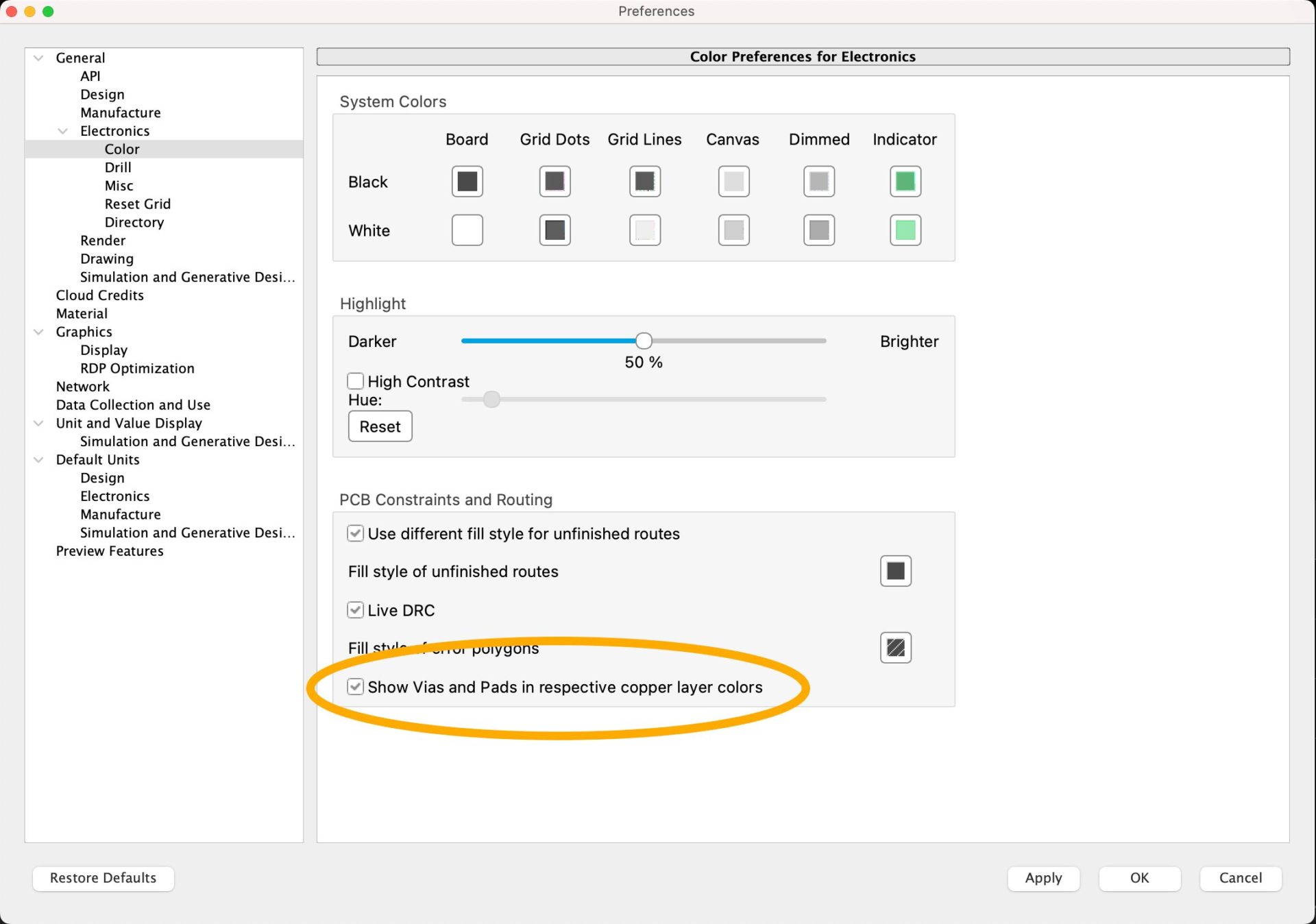
Pads are the connecting points of all electronic components. Some parts use surface mount technology, meaning they are soldered on the surface of the PCB. But others use through-hole technology, meaning these components are placed in drill holes that are platted and can be accessed from any signal layer. As you may already know, Fusion 360 can handle up to 16 signal layer boards. The pad size and shape are usually different on the internal layers. To see the actual size and shape of Pads and Vias on inner layers required too many steps. In this latest update, there is the option to have the pads, and the vias have the same color as the respective layer. Making it easier for you to view that the intended connectivity on the internal layers is what you expected. This new option can be found in the Fusion 360 Preferences setting, under Electronics > Color, enable the option “Show Vias and Pads in Respective Cooper Layer Colors.”
Generative Design
New in Preview! Manual Point Mass command
(as part of the Experimental Generative Solvers and Features Preview)

An outcome from generative design is only as good as its setup when it comes to truly meeting your design needs. In this update, we are adding the ability to simulate the loads associated with additional components attached to the item that you are generatively designing, without having to understand the forces that may occur at the interface of the connection. The manual point mass command will allow you to apply the mass of the attached components through the connection points to simulate the associated load. Being part of the Experimental Generative Solvers and Features preview, a manual point mass can be used in conjunction with other preview features like remote forces and constraints, symmetry planes and model, displacement or buckling limits.


Simulation
New in Preview! Plastic Injection Molding Simulation

You will find plastic injection molded parts everywhere in the consumer products, medical devices automotive interiors. In many cases the plastic part defines the exterior shape of the part, and holds all the technical pits on the inside dry and in place. The injection molding process can produce complex parts, in high quality, in a highly repeatable, cost effective way, and in large quantities. The process is incredibly efficient! However getting the part you designed, coming out of a Molding machine can be hard. Some basic issues with the design can cause the mold to be hard to completely fill, to have visible flaws in area of visible importance, and parts that are not the expected dimension (which can make assembly hard).
This new Injection Molding simulation technology in Fusion 360 provides a complementary workflow for an Engineer that occasionally works with plastic part and has to provide some feedback on the feasibility of injection molding these parts (‘is this design suitable for injection Molding’). You may not know everything about the plastic injection molding but you understand the basic principles, and that’s totally okay.
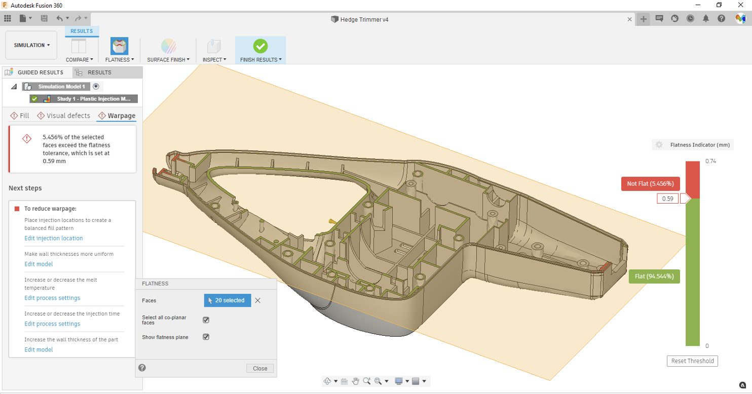
Some of the big differences in workflow are that we removed a lot of the onus of setting up the analysis for the user; a default material is assigned; an injection location is specified, and a molding process is setup, which is all that is required. The user can modify these if there if some decisions have already been made (better injection location or material. etc.), but if not, the analysis running with the initial defaults will give some good insights.
Another where the new workflow is different from the typical one is that rather than in addition to providing the results that the end user draw their own conclusions from, we have a ‘Guided Results’ experience where we provide the user not only with answers to narrowly defined questions: 1) will the part fill, 2) will I have sink marks and weld lines in aesthetically important areas and, 3) will I have problems with excessive warpage, but in case problems are apparent we also provide targeted suggestions to resolve the problem by providing suggestions to modify the design, change the injection point, etc.
This preview is not a replacement for the current Moldflow products, nor is this the end point. The technology provides a first starting point that can be built upon, and where the Injection Molding Simulation can start benefiting from the context in which the plastic parts are going to be assembled and used.
Learn more about Plastic Injection Molding Simulation
Drawings
New! Text Height Groups
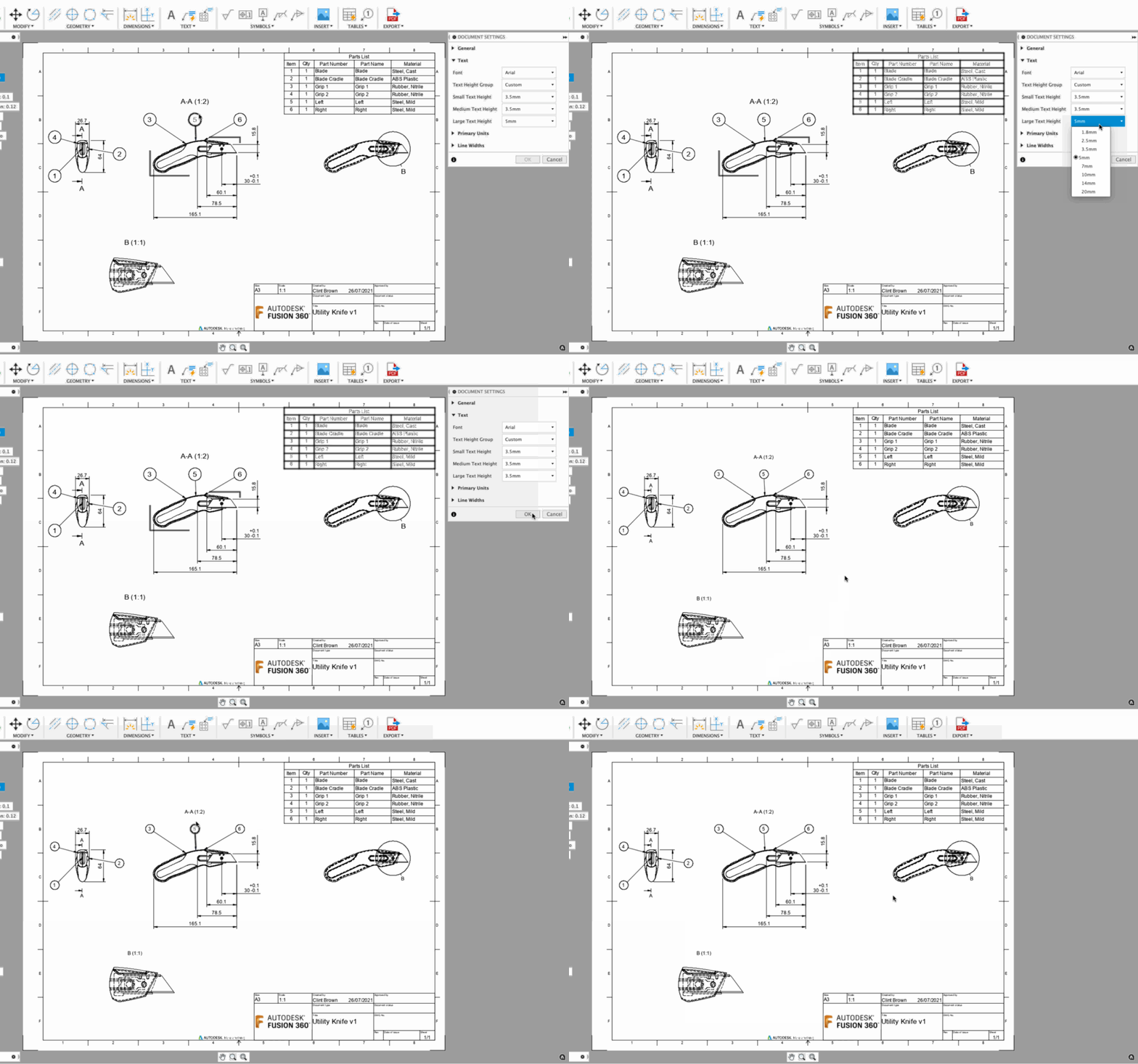
We’ve introduced more controls over text elements on a drawing. Text Heights Groups let you change the size of all text elements on a drawing proportionately. “Custom” Text Height Groups allow users to override groups of text elements, such as Dimensions or Balloons, yes that’s right, you can now control the size of your balloons.
Learn more about Text Height Groups
Improved! Custom Line Width group
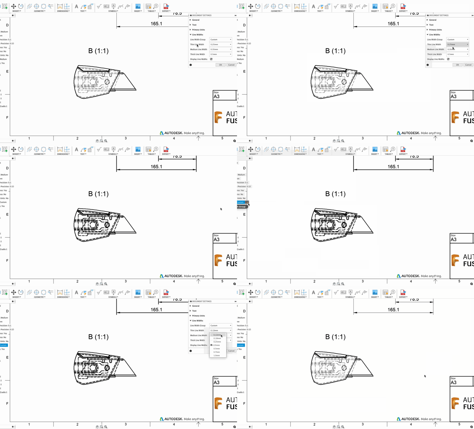
The “Custom” option found in Line Width Group allows you to choose a specific width size for a group of lines in your view. For example, you can go change your “Thin” Line Width group of lines to be the same width as your “Thick”Line Width group of lines. Giving you a little more control of the overall look and feel of your drawing.
Improved! Grips and moving views

We’ve overhauled our drawing grips, in the latest release, you’ll notice that grips are now round, bringing the drawings experience in-line with the rest of Fusion 360. We’ve removed redundant grips, which makes moving views a little more intuitive.
Manufacture
New! Flat Finish Strategy
Manufacture workspace > Milling tab > 3D Panel > Flat

The new flat finish strategy is designed to give you higher efficiency when it comes to finishing flat regions of your design. It has 5 key advantages over the standard Horizontal strategy:
- Recognizes filleted surfaces and avoids them
- Recognizes open pockets
- Supports Avoid/Touch surfaces
- Has a fillet option to roll around corners
- Has Machine Over Holes option
Recognizes filleted surfaces
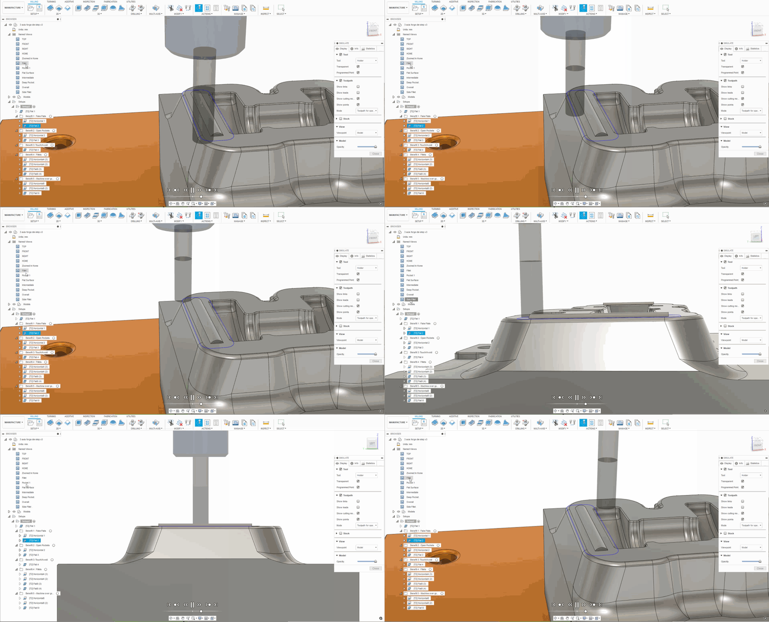
Flat finish strategy recognizes filleted surfaces and machines around them, instead of incorrectly interpreting them as false flat surfaces, like the Horizontal strategy does.
Recognizes open pockets
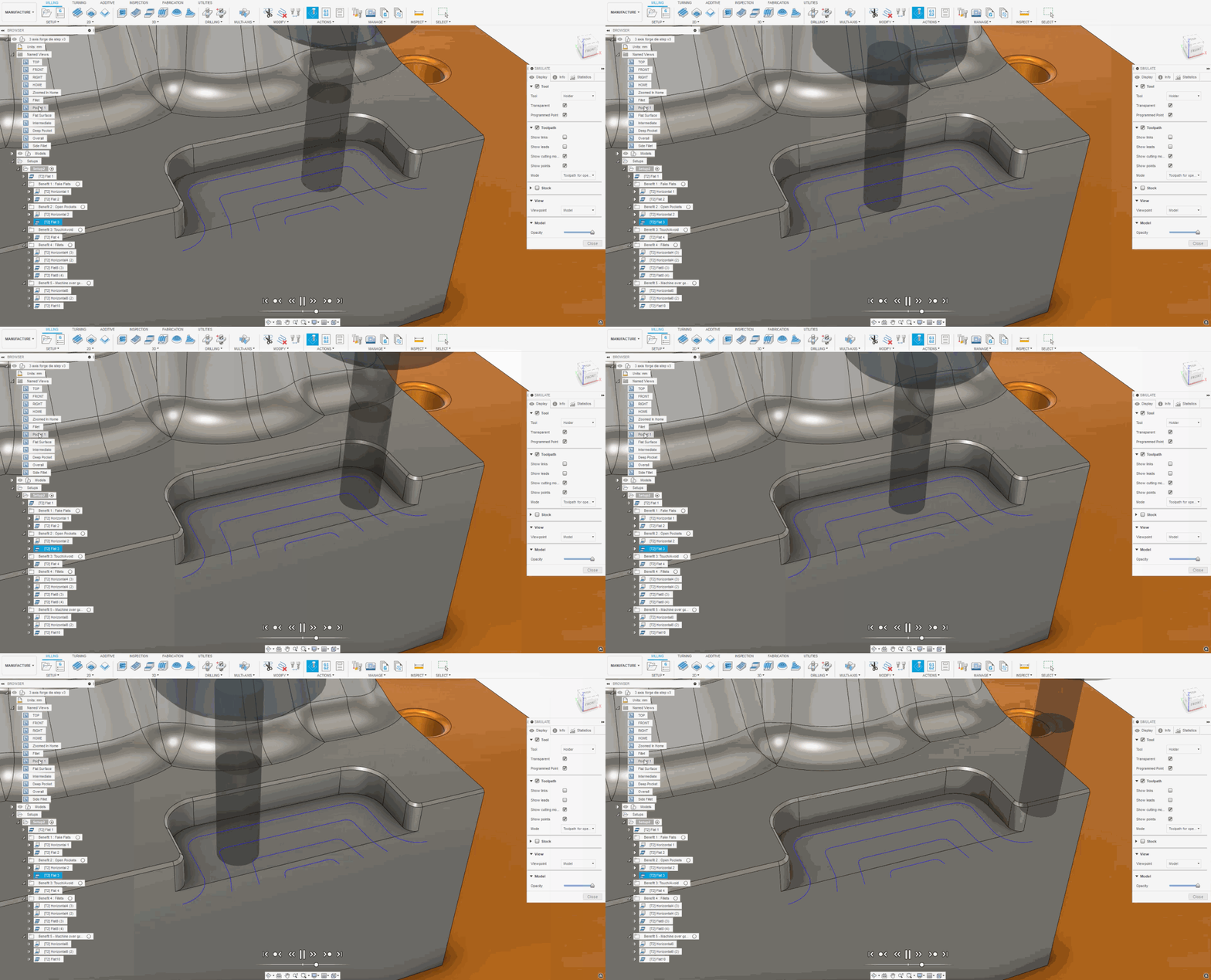
Flat finish strategy recognizes open pockets, and makes better use of entry and exit positions from outside the pocket as default paths. This will allow you to extend tool life, as well as maintaining a more consistent cutting engagement angle for better surface finishes.
Supports avoid/touch surfaces
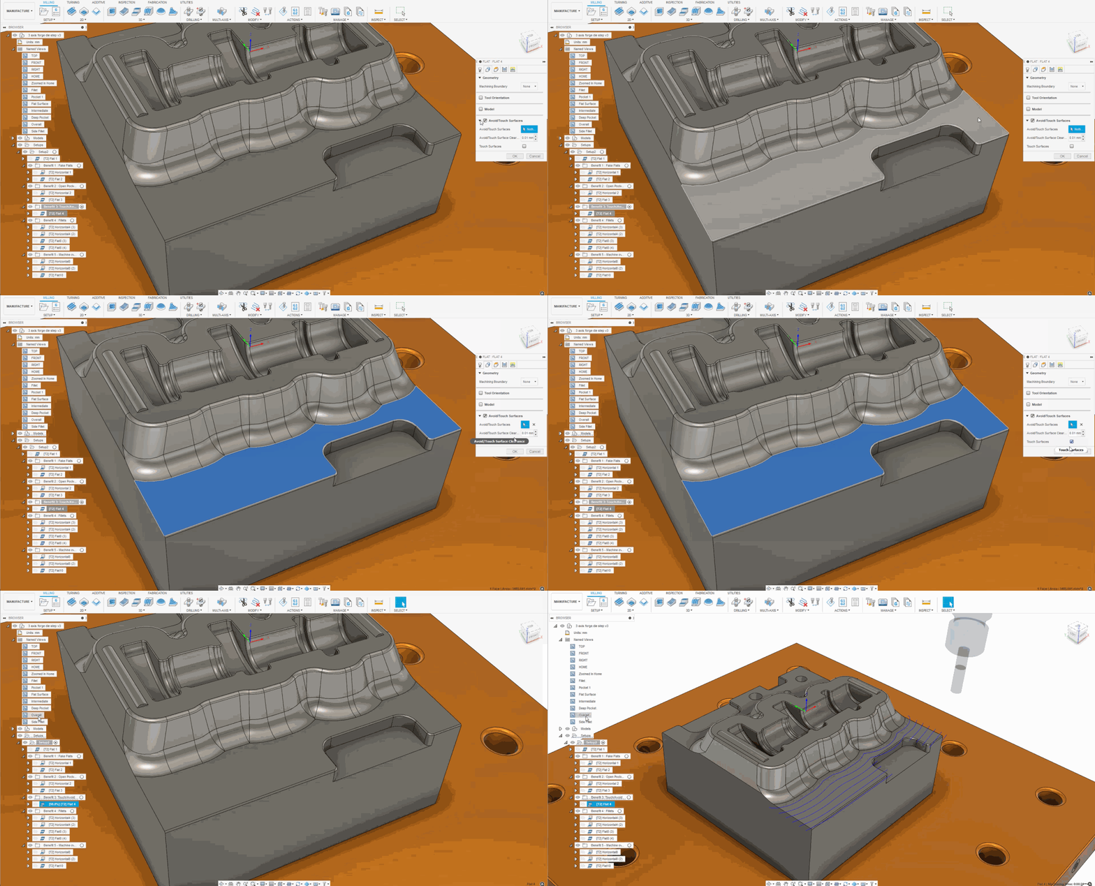
Flat finish strategy supports touch/avoid surfaces. This can speed up programming time, and gives you more control over where you want to machine.
Fillet Option
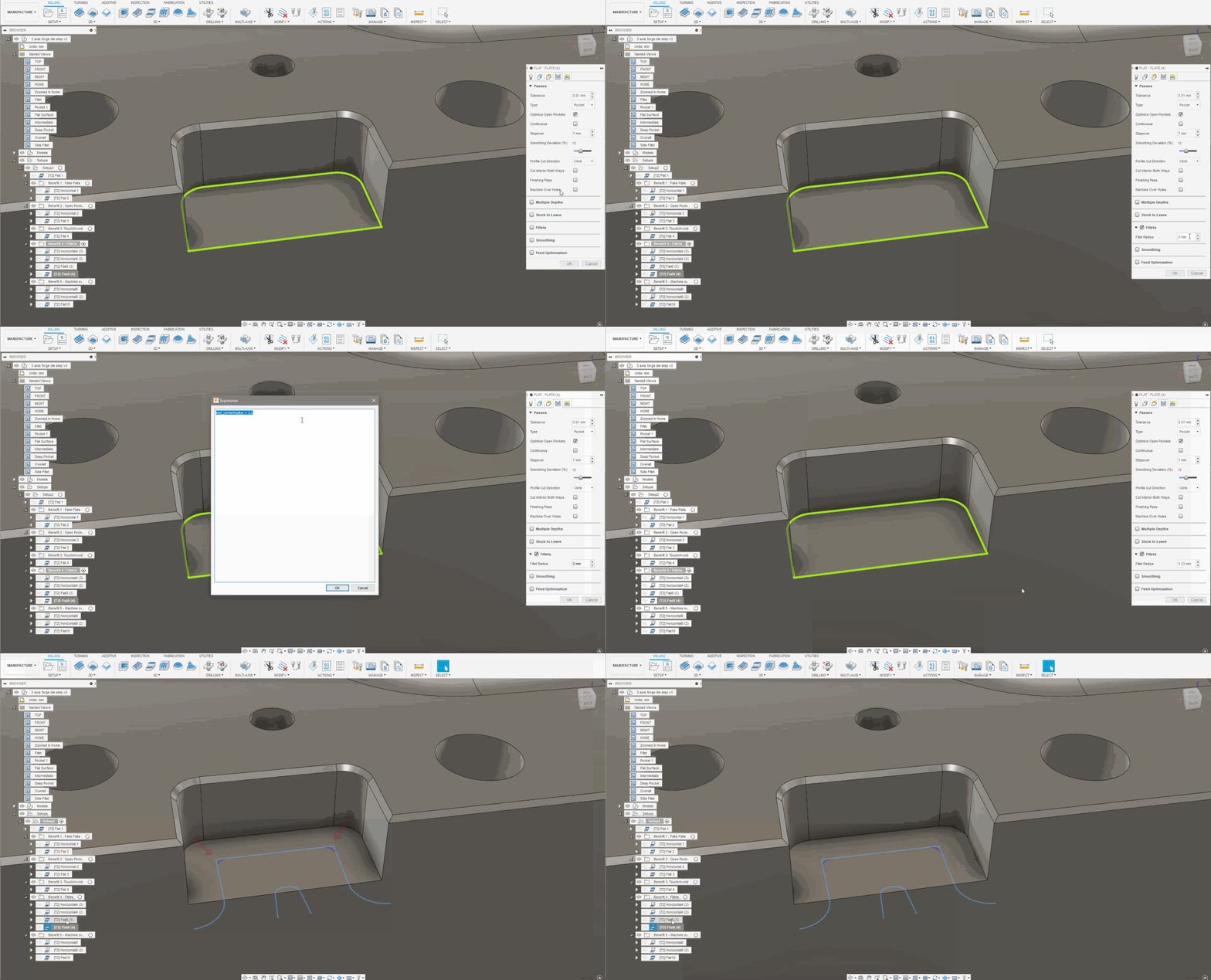
Enabling the Fillet option within Flat Finishing strategy enables the tool to machine sidewalls to the programming size, but also makes it roll around the corners to avoid over engagement.
Machine Over Holes option
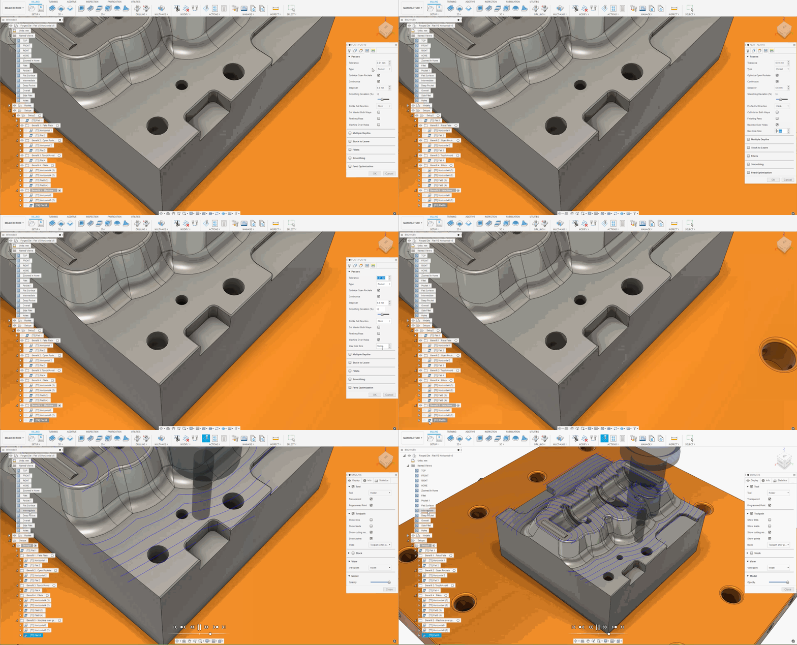
Flat Finishing now has the option to machine over holes with “machine over holes” button, leaving you a more efficient toolpath as well as better surface finish.
Learn more about 3D Flat Strategy and 3D Strategy reference
New! Post Process from NC Program
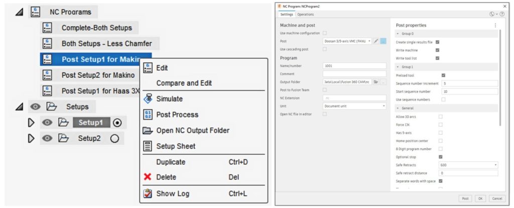
To create a unified experience for both Mac and PC users, the Post Process functions have been updated into the NC Program function. NC Program gives you one place to Post Process NC Code, Simulate toolpaths and create Setup Sheet documentation. This has been in preview but is now set as the standard post processing experience. Selecting Post Process from the Actions toolbar will be the same as selecting NC Program from the Setup toolbar.
Note: If you experience any problems using NC Program to post process your files, you can revert to the legacy post process function by changing the Preferences > Preview Features and enable Post Process NC Code with legacy post process dialog.

New in Public Preview! Steep & Shallow Undercuts
Profile > Preferences > Preview Features > Machine Undercuts for Steep and Shallow

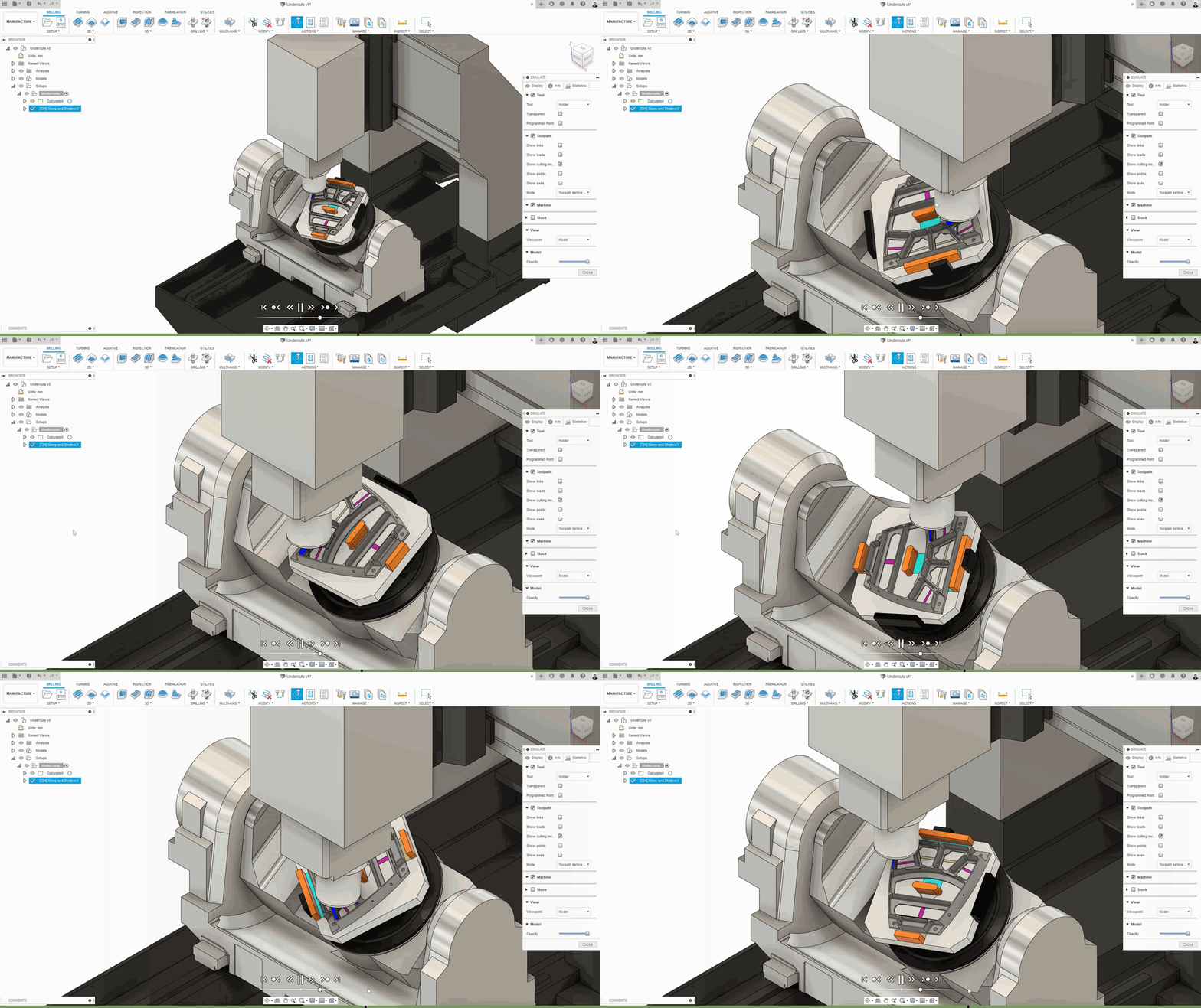
Now available to try for free is the ability to machine areas that were previously unreachable (undercuts) due to overhanging geometry. By setting your threshold angle at 0, you’ll now be able to use Steep & Shallow and reach those pesky areas in a single operation. This will work in 5 axis with Automatic Collision Avoidance, as well as 3 axis with lillipop, disc, or dovetail cutters.
Learn more about how to machine undercuts with steep and shallow.
New in Preview! Automatic Collision Avoidance for Rotary
Profile > Preferences > Preview Features > Collision Avoidance for Rotary


Another free preview functionality to try is Collision Avoidance for Rotary. As it is shown in the preview option description, Collision Avoidance for Rotary will automatically tilt the tool and avoid collisions while preserving the 4-axis motion at the same time. This works much better than Shaft & Holder, as it actually avoids collisions, and doesn’t just find and remove the colliding segments.
Learn more about Rotary Collision Avoidance.
Improved! 2D Profile Strategy now has “Finishing Overlap” Option

Previously only available in the 2D Contour milling toolpath, you now have the option to specify a Finishing Overlap distance for your 2D Profile toolpaths as well. This will help improve the consistency of the cut when manufacturing components with Laser, Plasma or Waterjet machines. Taking advantage of Finishing Overlap will enable you to create cleaner cuts by avoiding the lead in and lead out occurring at the same point. It can also eliminate secondary deburring/grinding operations downstream, reducing manufacturing costs.
See the Help for how to generate a 2D Profile toolpath
Improved! Diameter range added to Bore / Circular / Thread Geometry selection
Manufacture > Bore | Circular | Thread > Geometry tab > Minimum Diameter & Maximum Diameter
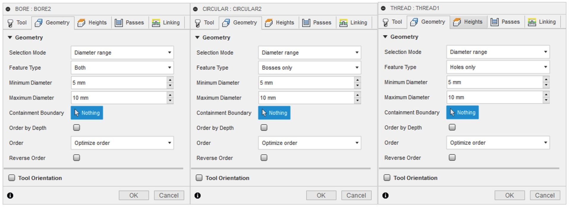
Now when you perform a Bore, Circular, or Thread operation, you’ll notice that under the Geometry tab, you now have the option to specific a diameter range between Minimum diameter to Maximum diameter. Once set, the operation will filter for Hole, Boss, or both. Having the ability to specific a diameter range can help you reduce repetitive mouse clicks and potential human error, thanks to smarter hole selection.

Learn how to generate a Bore, Circular, or Thread toolpath.
Improved! Hole Recognition: Template Libraries and Meta Data
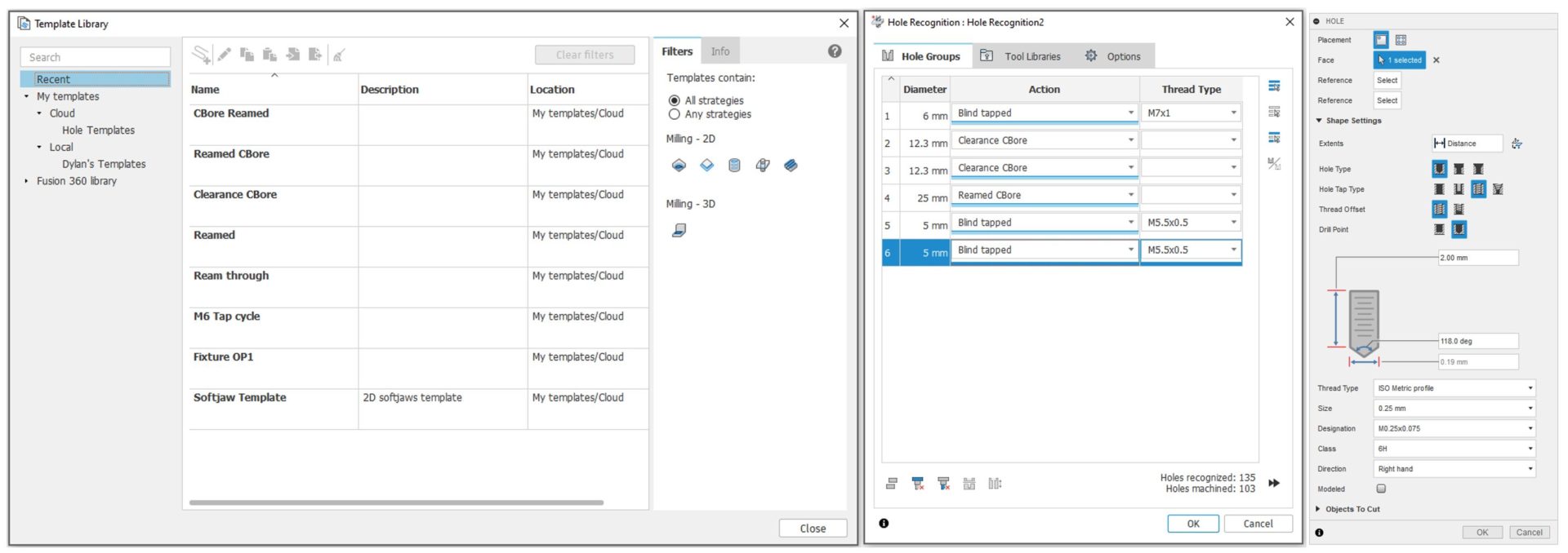
We’ve updated Hole Recognition with a few new improvements: better link between the template library as well as the ability to carry meta data, extracted from the Hole command. In the Template Library, you’ll now be able to save Hole information and associate them to a saved template. Hole recognition will choose the right thread type based on the Hole command used in the Design workspace. These improvements are aimed to increase productivity, you can spend more time doing the important stuff: shipping awesome products and getting paid.
Note: More information on creating and using Template Libraries
Improved! From Setup Stock option in Rest Machining for Turning
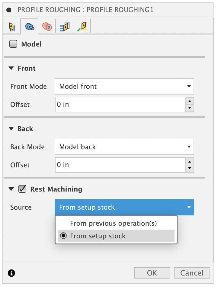
Now in the Rest Machining option for Turning strategies, you have ability to select “From setup stock” as the Source. You’ll be able to use cast and forged solid models for the Setup stock reference, and it will create toolpaths only in the places that are needed. This will yield higher efficiency and reduce cycle times. For example, The yellow below represents the solid stock model. Regardless of the number of step-overs specified, only 3 step-overs will be generated to machine the remaining stock.

Improved! Automatic naming Convention for Nest & Sheet nodes

We’ve improved the naming convention for Nest & Sheet nodes to be automatic and rule-based. Now Fusion 360 will update the names of all nests and sheets in the browser and Nest Reports when a change is made. Naming rules are also stored in the Assets folder, meaning every team member in your team hub can have access and share the same naming rule for the project.
Additive
New! Makerbot, BCN3D, and Flashforge printers support

New! Spiral Vase option in Print Setting Editor

Now within the Print Settings Editor, you’ll have the option to enable Spiral Vase. This option is commonly used to print aesthetic and seamless 3D objects while maximizing material and time by printing an outer perimeter with a single thickness, taking shape like a vase. Here is a good video describing what vase mode is.
New! Self-paced learning & tutorial for Additive Manufacturing
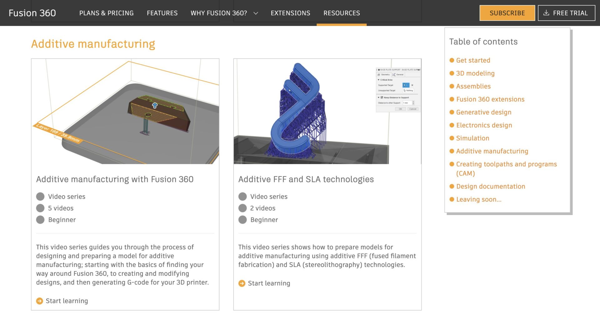
We’ve enhanced the learning content available to get you started with additive manufacturing.A new video series is now available on the Fusion 360 self-paced learning site. The series includes videos showing how to prepare models for additive manufacturing using additive FFF (fused filament fabrication) and SLA (stereolithography) technologies.

We’ve also added a new tutorial in the online help that provides step-by-step instructions on how to prepare a desk hook for 3D printing using a Formlabs SLA printer.
Known Issues and Fixes
To see details around this, our extended list of fixes, as well as known issues, check out known issues and fixes for August 2021.
Fusion 360 Insider Program
Become a Fusion 360 Insider and get early access to what’s new

Apply to join and get exclusive early access to next production version of Fusion 360, two weeks before it is released to the everyone else. Along with getting early access, you will also be able to:
Get your hands on new features, before everyone else
You’ll be the first to get what’s coming in next product update: new tech, improvements, and fixes.
Know in real-time when updates are happening, what’s new, and what’s coming
Know, in real-time, when we are deploying an update and what’s coming in the next one, straight from the development team.
Gain exclusive access to the Insiders Lounge and report issues
As a member, you’ll have access to our private Insider Lounge, where you can engage with other Insiders, Autodeskers, and report bugs and issues directly within the same space.
One thing we do want to be clear about: this is not a beta program. This is early access to the next production update release by installing and running a pre-production build. If you are a content creator, add-in developer, power-user, or just someone who wants to stay ahead of the curve and test new workflows, this is a great opportunity for you to be a part of something special. To join this program, simply apply by filling out the application form along with an NDA. Once your application is approved, you’ll be able to access the virtual Fusion 360 Insider Lounge, install the pre-production build and start testing out the newest features!