v2.0.3257
We got reports of our streamer log files getting bloated to the point where it was taking up a tremendous amount of storage space. Turned out that the log files just kept growing and growing without any supervision. We put it on a diet and it’s now it’s back to being lean. We’ve also made it so that it gets deleted automatically if it ever decides to bloat up again.
August 16, 2017 – What’s New
v2.0.3254
A couple small but important fixes here:
- We fixed an issue where Fusion 360 was crashing on startup on some Mac machines.
- We found some instances where out-of-date designs weren’t flagging you that they were out-of-date, even after you’ve saved a change. This is now fixed.
August 8, 2017 – What’s New
v2.0.3253
This update is our big summer blockbuster. Our glee is real about this one, as it marks a major milestone in the evolution of Fusion 360. Not only does it include some applause-worthy improvements to existing design tools, we’re also introducing cutting-edge preview workflows and brand-new functionality that will be welcomed by many of you. Enough talk. Let’s party.
[toc]
Sheet Metal now available
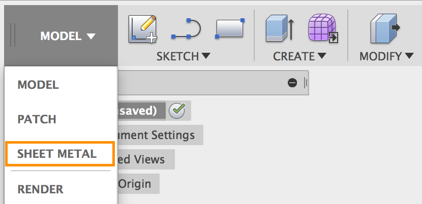
The wait is over! Ever since we began our limited preview of the sheet metal workspace back in March, we’ve been inundated with how many of you have signed up to try it out. Over 2500 of you. Working with many of you, we heard your feedback, kept iterating, and instead of going up the ladder of our normal preview process, it’s out of limited preview and is now available to everyone to use!
For those who are new to this functionality, Sheet Metal lets you design and manufacture parts by creating geometry that can be bent into a 3D part. Bend angles are dictated by a set of rules that you can edit, override, and store for future use. Think of a computer case, metal brackets, housings, or electrical enclosures. This functionality is critical to many of the products around us such as electronics, fixtures, and industrial machinery. It has been the number one most voted idea in our IdeaStation, so needless to say, it’s a big deal.
Know the terms
Sheet Metal has many industry specific terms you may or may not be familiar with. That’s why we have a whole section on our learning site dedicated to Sheet Metal. Check it out if you’re new to this, or use it as reference if you need a refresher.
Here’s a quick run-down of features you’ll find in the Sheet metal workspace.

Single Flange tool – One flange tool, multiple uses. Here are all the different kinds of flanges you can create.
- Base and Edge Flange – Grab a face or an edge of a sketch and create flanges with familiar Fusion 360 controls.
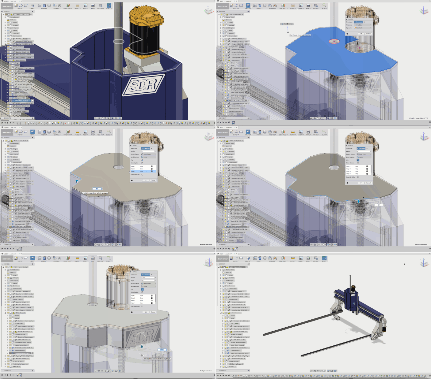
- Contour Flange – Pick an edge of a flange and then a sketch profile. Fusion 360 magic ensues. Great for hems!
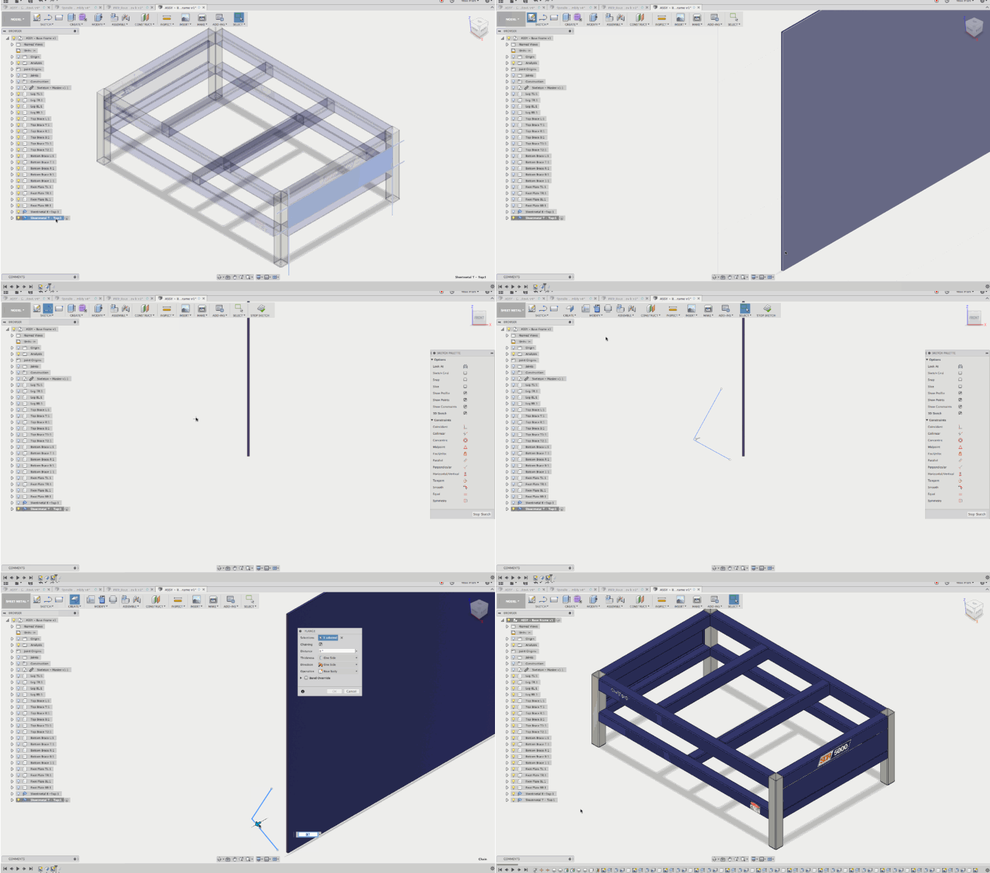
- Miter Flange – Create miters you need them and specific miter gaps, all within the Flange tool.
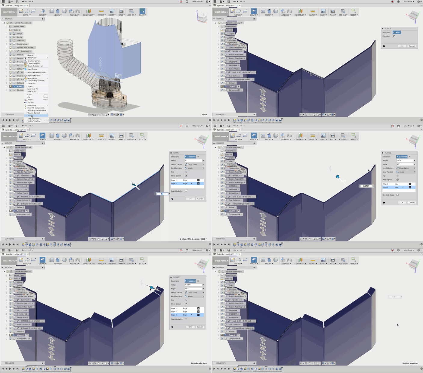
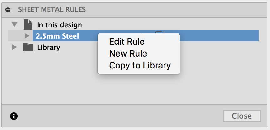
- Sheet Metal Rules – Set bend rules, edit them, or save frequently used ones to your bend library for future use.
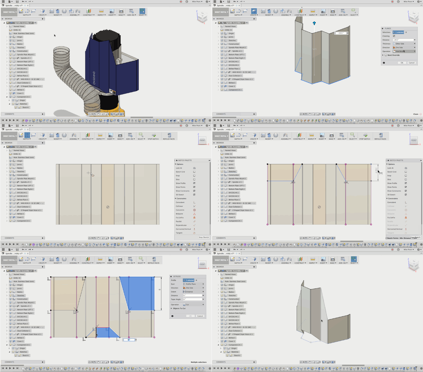
- Unfold/refold tool – unfold your sheet metal part so that you can design features in an unfolded state. Fold it back up to see how those features look.
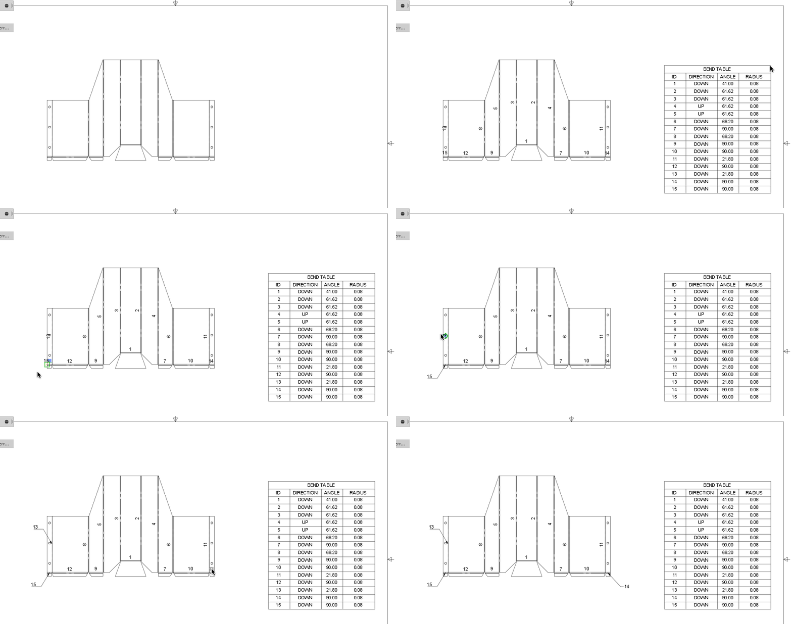
Documentation in 2D Drawings – document and dimension your flat patterns in the 2D Drawings workspace with bend tables and bend Identifiers.
You can create bend tables by selecting the Tables tool. We have built in logic so that Fusion 360 knows what kind of table (part list, bend table, or empty table) you need based on the view that’s on the sheet.
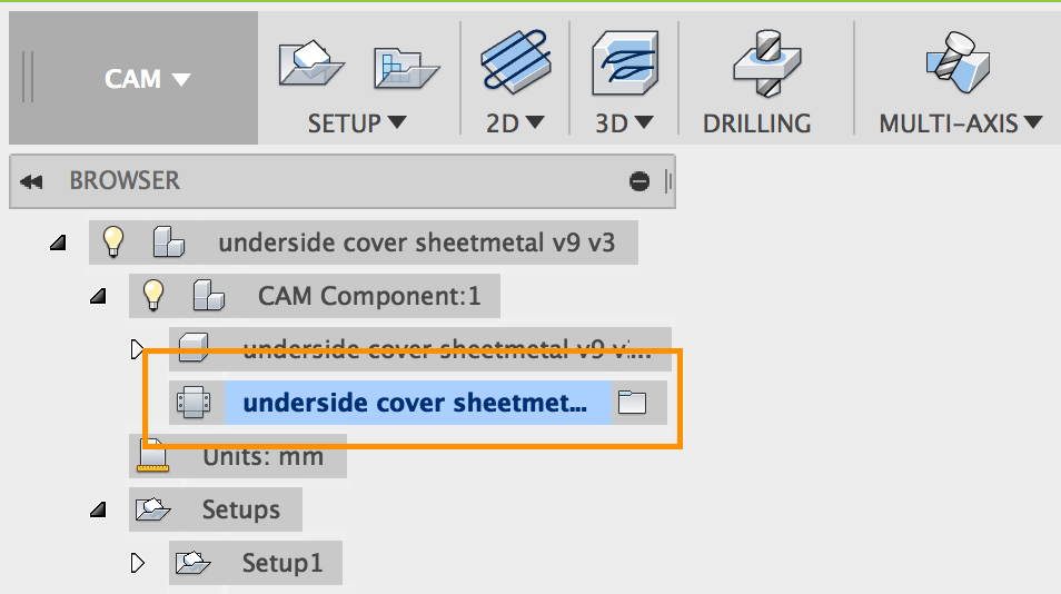
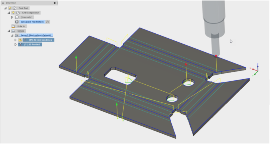
Manufacture in CAM – Bring your flat patterns into CAM and set up 2D cutting strategies for your waterjet, laser, or plasma cutters.
*Join the Sheet Metal Challenge: Design a bumper*

There’s no better way of diving into new functionality than to design a real world part and manufacture it with your own hands. Coincidentally, one of our team member’s truck needs a new bumper (cuz you know, #offroadlife). We teamed up with FARO, got the front end of truck scanned, and now we’re throwing down and challenging you to design a brand new bumper using sheet metal functionality in Fusion 360.

There will be 3 grand prizes, where the 1st place winner win a trip to California and experience his/her winning design get made, as well as win a pass to Autodesk University 2017. So yeah, let’s see what you’ve got!
Get the details about the challenge here. Good luck!
Reliability
New! Selective Cache is now available
For the keeners out there, you might remember us talking about ‘Selective Cache’ in a Fusion Forecast a couple months back. In that article, we laid out our three-phase approach to making the offline experience seamless. Selective Cache represents the second of the three phases, and is a significant milestone.
Previously if you wanted something to be accessible offline, you’d have to open the design so that Fusion 360 knew to cache it. Doing this 100 times is no laughing matter (more like a huge waste of time), so now, you can select exactly which designs/projects you are working on, and Fusion 360 will cache and make them available for offline editing.
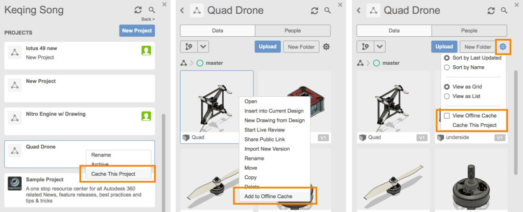
Here’s how to do it: Selective Cache lets you cache by design, design folder, or an entire project. You can do this 3 ways:
1. Right click on a top-level project and select Cache This Project.
2 .Right click on a design within a project and select Add to Offline Cache.
3. Click on the gear in a project and select Cache This Project.
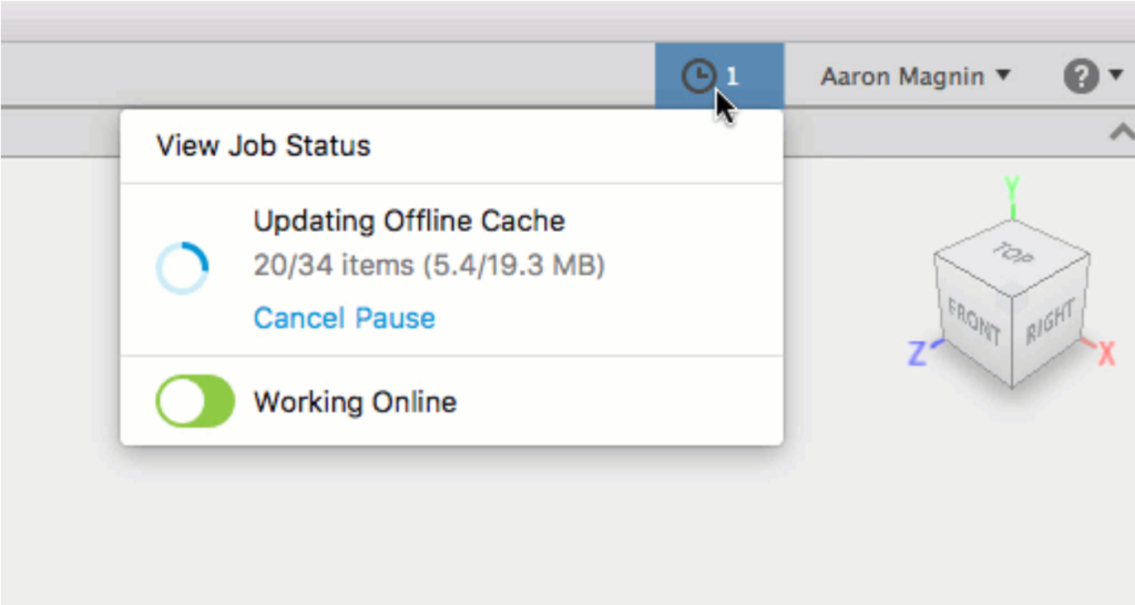
While the cache is happening, you can monitor its progress by clicking on the job status area. We won’t pop anything out for you – you’ll have to open it if you want to see what it’s doing.
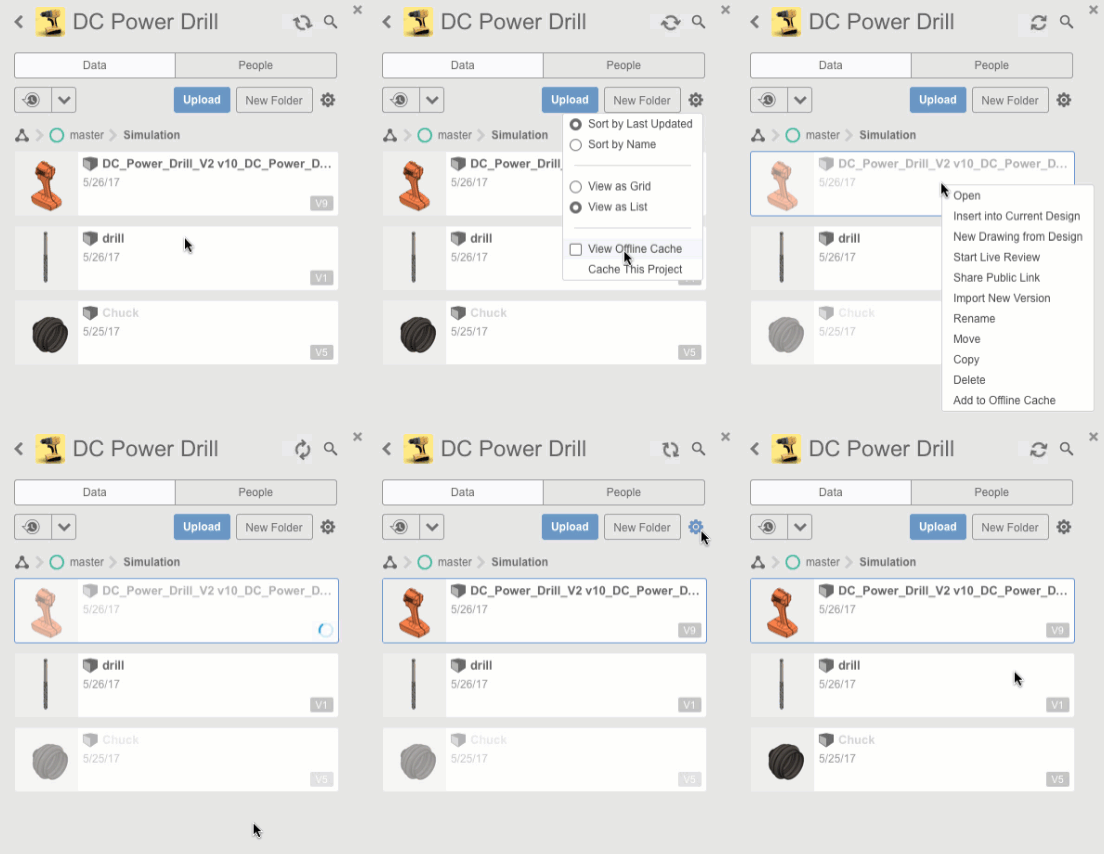
How do you tell what’s been cached and what hasn’t? Good question. There’s a handy option called View Offline Cache; it’ll let you see which designs are cached and which are not (based on thumbnail visibility). If you check this and nothing is grayed out, then you have the entire project cached.
Two important things to know:
- Caching a design/project is a one time cache. Cached designs will not be automatically synced with newer versions – you’ll have to recache them if you want the latest changes available offline. Automatic syncing will come at a later phase of the project.
- Cached designs, including those cached selectively, are cleared after 60-360 days of inactivity, depending on what you have it set to in your preferences.

We’re thrilled to be releasing this highly anticipated functionality, not only because it’s an important step in the right direction, but it’s another case where we were able to deliver on a promise in the timeframe we estimated. We know that’s not always the case, but we certainly try. Big kudos to the development team on this achievement!
Design & Modeling
New! Thread Display option in Browser > Document Settings
If you have a design with lots of thread features, having them fully modeled all the time can potentially slow down the performance of your Fusion 360 session.
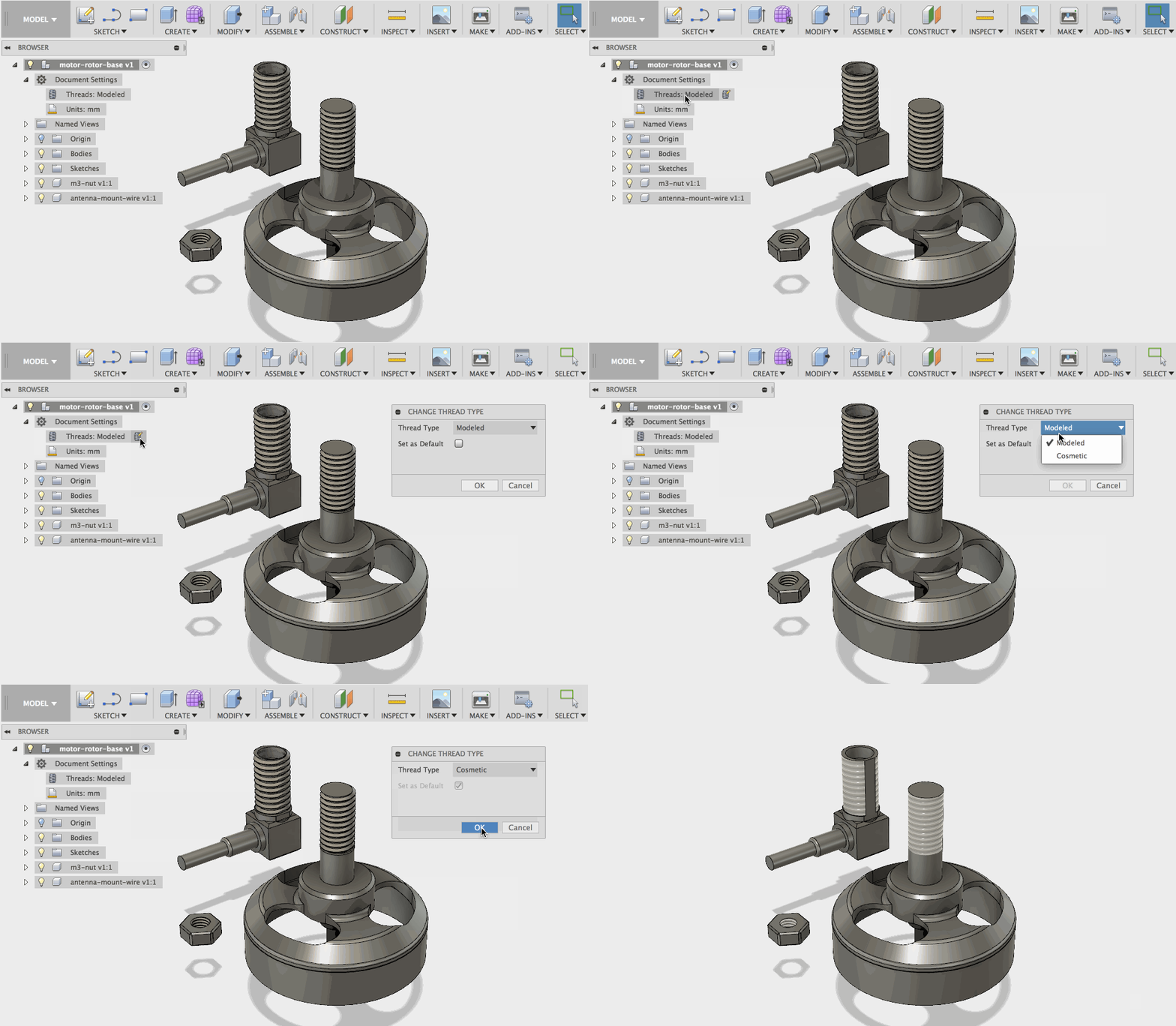
Now there’s a section in the browser called Document Settings, and under it, you’ll be able to switch thread display between “modeled” and “cosmetic” for ALL components/parts/bodies within the same document. Doing so will relieve Fusion 360 from performing extra computes on those threads, and putting it in more important processes.
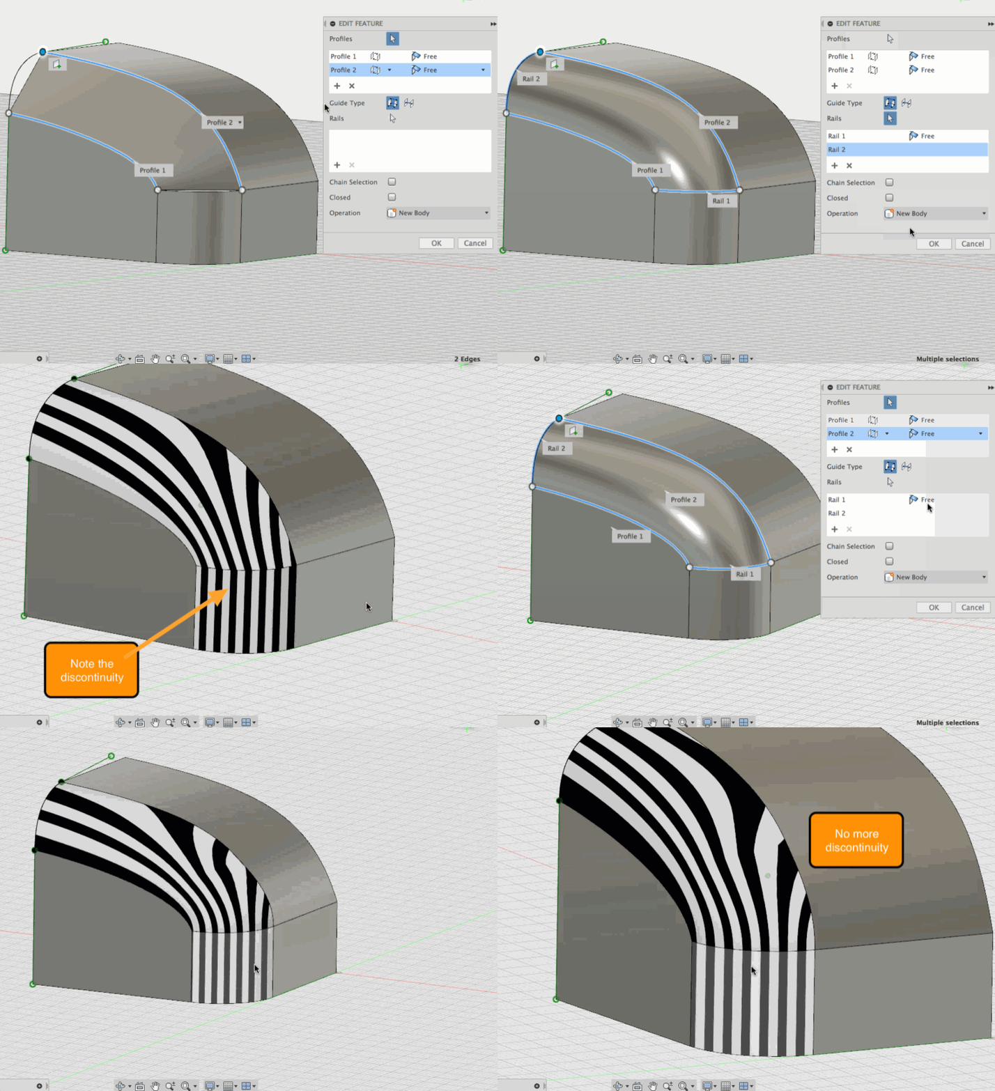
New! G1/G2 Continuity for Loft Rails
Previously when you lofted a surface, there wasn’t an option to control the continuity for rails, and when you applied a Zebra analysis on your loft, you could see a break in the seam. Womp womp. Now, the continuity can be controlled independently for both profiles and rails in the surface loft command, by selecting what kind of continuity you want for each rail. Selecting Smooth will make your surface G2. A very welcomed improvement. Huzzah!
New! True 2-Rail Sweep Extent Control
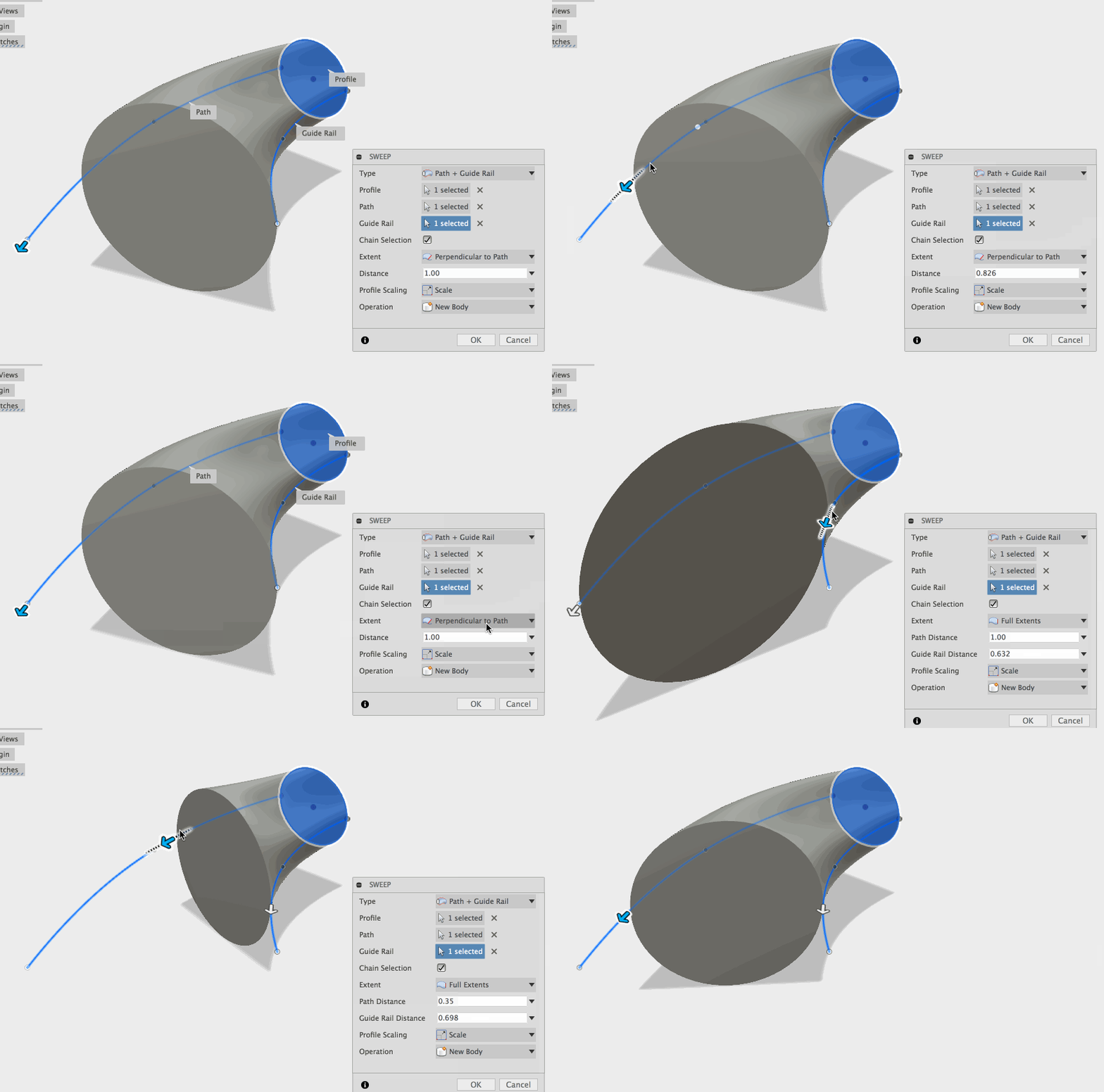
Another major improvement here is giving more accuracy over the termination properties of sweeps with guide rails. Before, the distance of the sweep depended solely on the length of the path, and not the rail, which made this more of a path + rail solution than a true 2 rail solution. Now we’ve added a “Full Extents” option which allows you to choose how far down each the path and rail your sweep will travel. Rad.
Fixed – Combine tool now previews correctly
We’ve gotten reports of weirdness occurring during a Combine > intersect operation, where the cut/intersect preview doesn’t correlated which where the bodies are actually located. That ain’t right. Apparently it was a graphics issue, and now it’s all sorted out.
Fixed – Joints no longer remembers Offset Values
This one dealt with when you created a mate, but input an offset value for one of the inputs. Fusion 360 remembered this value and then applied it to future joints, which was rarely what you wanted when it comes to assemblies. Now values will no longer be remembered.
Sketching
New! Arc Slot Creation Tools
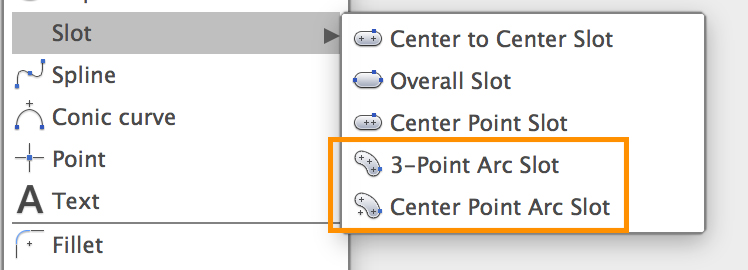
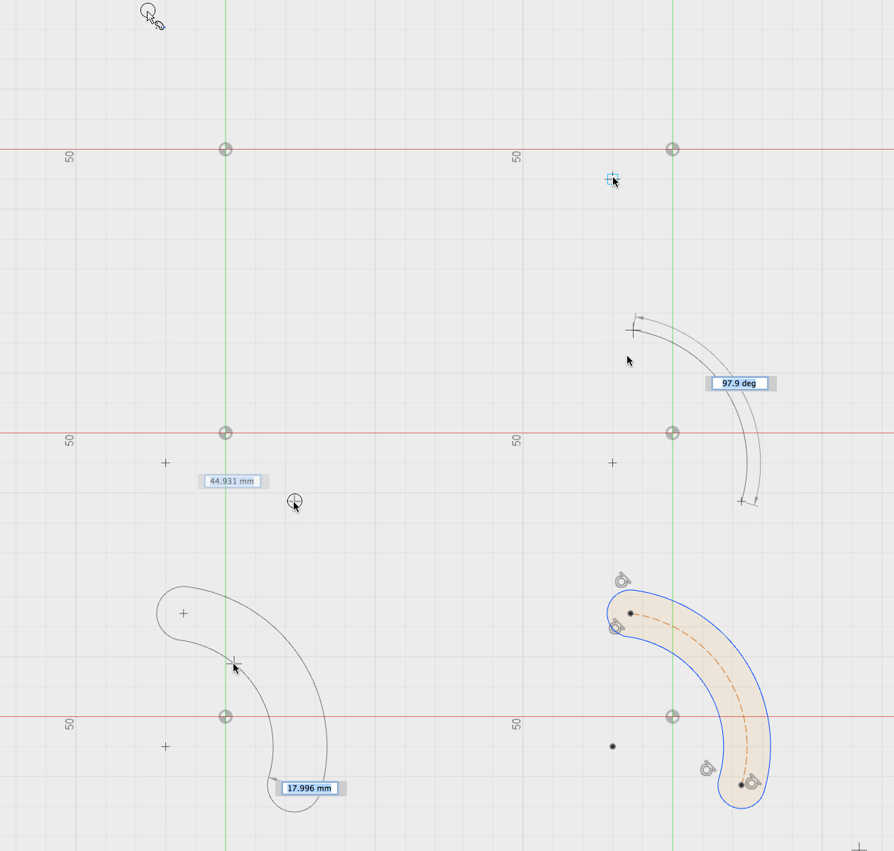
You can now create arc slots in the Sketch environment! There are two new tools under the Slot section of Sketch: 3-point Arc Slot and Centerpoint Arc Slot.
 Create a Three point arc slot by selecting both ends of the arc first, then the radius, then the desired width.
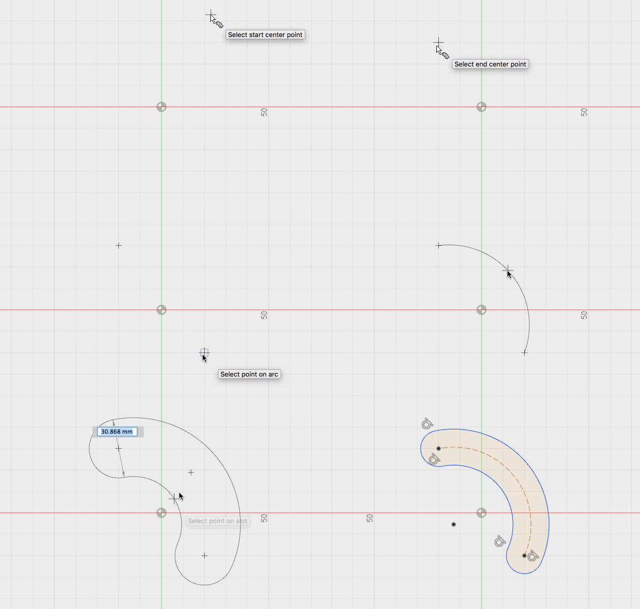
 Create a Center-point Arc Slot by placing the center point of the slot first, and then defining both endpoints of the arc, following by the last click, which defines the width.
New! Create Tangent Dimension
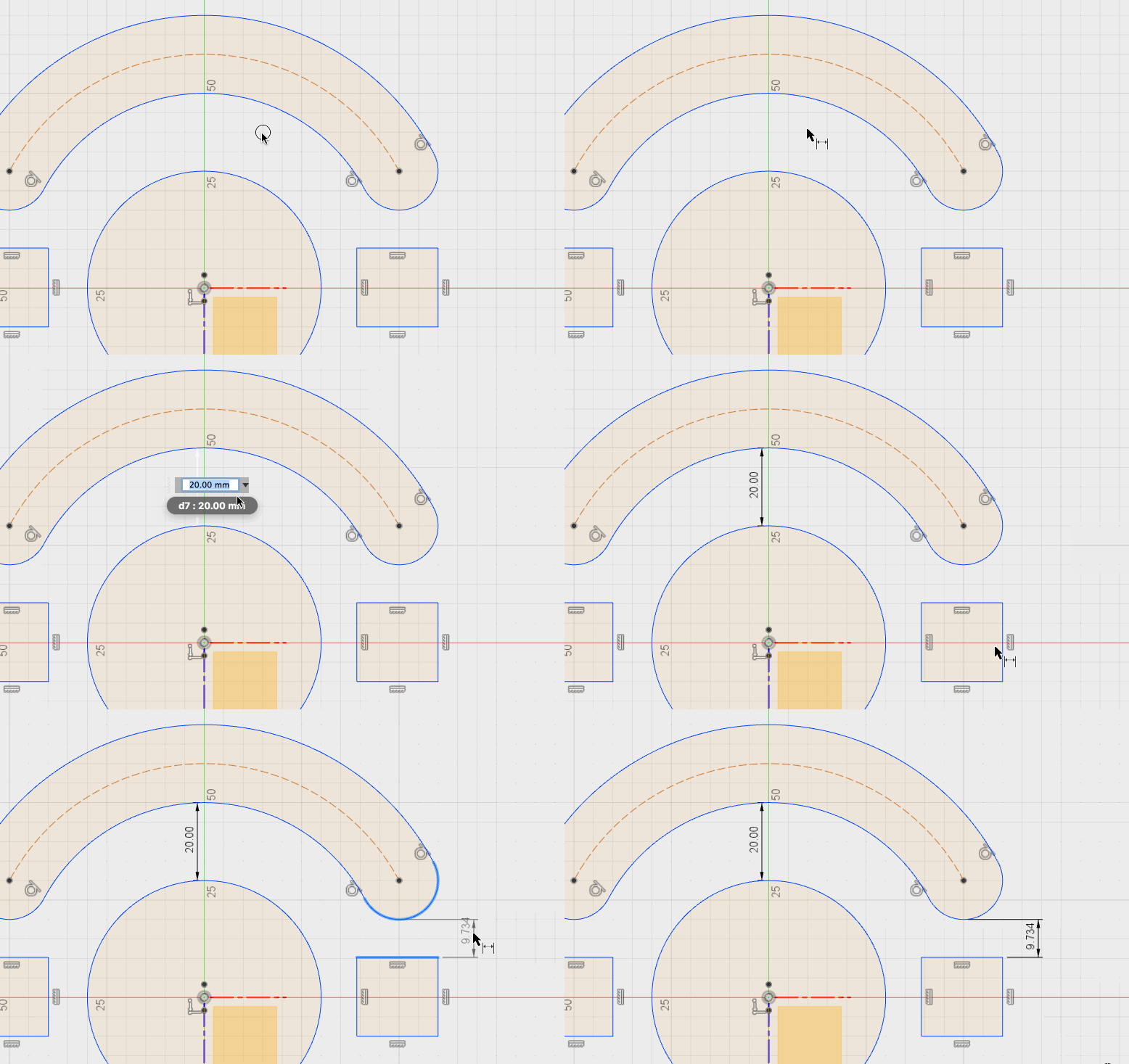
Oh, it get’s even better. Remember how previously when you’re dimensioning your sketch, you were only able to dimension from the center of a circle or arc to another edge? Now you can dimension from the tangent arc to the other edge. Yaaas.
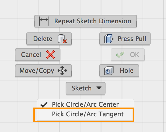
Select the Dimension tool, right-click, and instead of Pick Arc/Circle Center, check Pick Arc/Circle Tangent. With that selected, you’ll be good to go.
Simulation
FYI: Suppress Preserved Regions in Shape Optimization
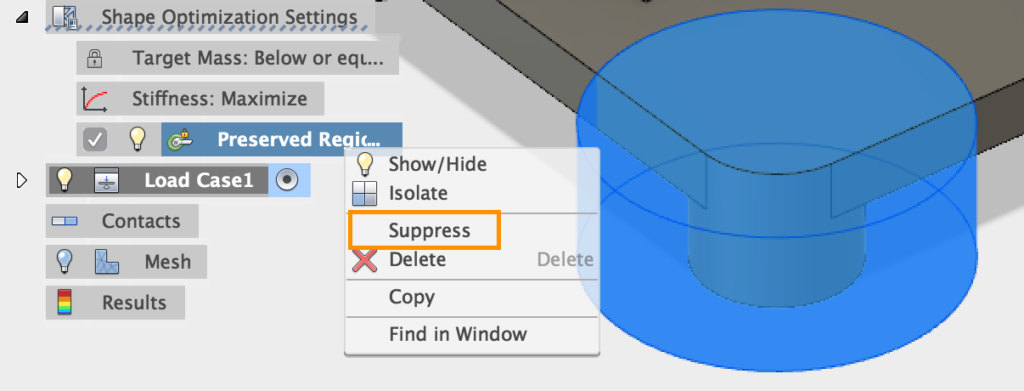
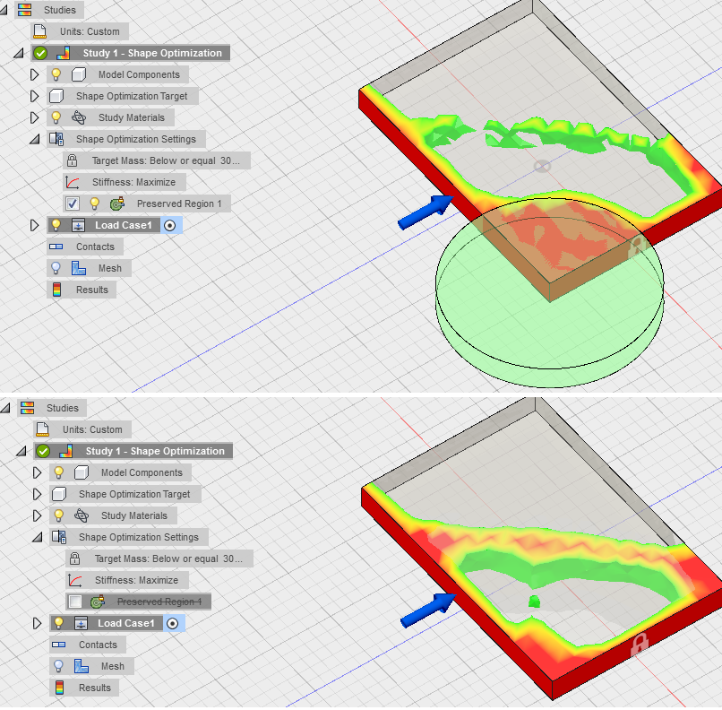
When setting up a Shape Optimization study in the Simulation workspace, you’re able to preserve a region of your design so that the study leaves that region alone. We didn’t highlight this in the last update (kinda just snuck it in there), but you do have the ability to suppress the preserved region so you can get quick comparison of what the study would look like without that region preserved, without needing to physically modify the design itself.
New! Pre-check now checks for material type
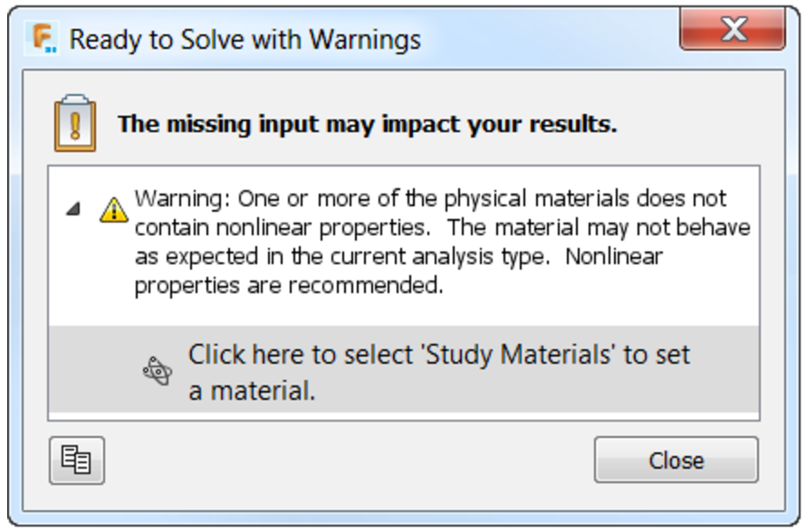
The pre-check functionality will now check the material type versus the study type. This is to make sure you are using the appropriate material type for your studies. If you are creating a Nonlinear study (Nonlinear Static or Event Simulation) and die not define a material with nonlinear properties, Fusion 360 will let you know with a brief message.
HSM CAM
Improved! Turning Confinement
Previously in Turning operations, you had very little control over the front and back confinements since they were based off a fixed origin point that had be set for the part. Lonnie.Cady suggested that whenever you’re turning a part, you should be able to specify the stock front, stock back, model front, model back, chuck front, and the new reference origin (if needed). We thought it was a great idea, and so we made it happen.
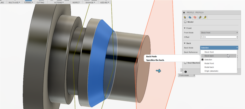

You can also use any of these areas to set your part Zero. Need a specific offset? You got it. Select a reference point and use the arrow manipulator to specify a new offset. Offset values can be positive or negative from the reference point.
New Training Series: Turning – Live Tooling, OD & ID Machining with Sub-Spindle Transfer
This 11 part series includes full written documentation with videos, covering the complete process.
Learn about essential Fusion features like:
- Merging Models
- Changing the Models Appearance (Material)
- Live Milling on the Face, Duplicating Toolpaths
- Cross Milling Slots
- Circular Pattern
- Sub-Spindle Part Transfer
- Sub-Spindle ID Turning and ID Threading
Improved! Tool Library
- Looking for right tool to use for a job should be effortless. We made a number of experience improvements to the tool library that should make your lives easier.
Lonnie.Cady yet again reported a weird glitch where his “x” (clear all filters) icon was floating the wrong location. We got it to go back in line. - The tool library how shows the library tree by default when you’re opening it from an operation.
- Tool Filters will be cleared when the tool library is opened. No operation filters or tool filters will be active.
- Just like how HSMWorks and InventorHSM Tool libraries behave, now when you open your tool library in Fusion 360, it will open to the current document library instead of all libraries.
- When you’re looking at a document library, instead of being all expanded, tool operations will not be collapsed by default.
2D Drawings
Improved! Re-associate dimensions by dragging grips
Previously if you made a change to the design and updated your 2D drawings to reflect the changes, sometimes you got the yellow “!” disassociated badge. When that happened, you had to select re-associate, and then re-select the points /edge you wanted the dimension re-associate to… talk about a lot of steps just to get your dimension right again! Yeah, we made this better.
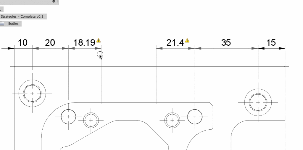
Now if there is a design change, you can update your drawing dimensions by selecting the dimension (this displays the grips), and click-dragging it (or grip-editing) the dimension grip to a new point on the drawing view to update the dimension. This updates the dimension and makes it associative to that geometry in the future.
Improved! Dimension Break
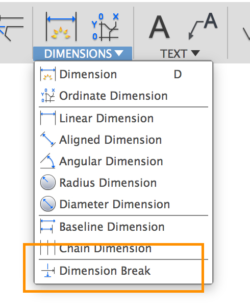
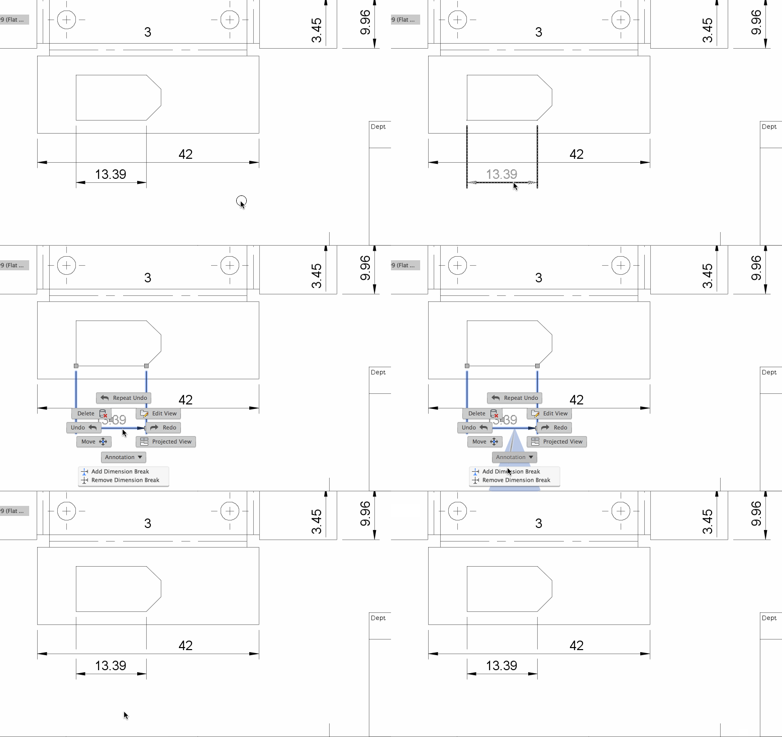
Jkelindberg posted about this a while back, and now we made it happen. Now you can create breaks at the intersections of your dimension lines so that your drawing can look cleaner. Do it 2 ways:
- By selecting the tool under the Dimensions drop-down menu.
- By selecting a dimension and then right-clicking/accessing it through the marking menu.
Improved! Dimension Group Stretch
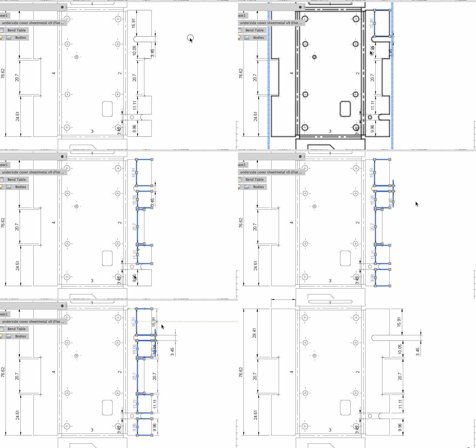
We’ve all been there – tediously clicking away to stretch dimensions one by one. KMP shouted this request from the hills at AU 2016 and we got to work. Now you can batch select a group of dimensions by holding down SHIFT or simply using a window cross-highlight, then select one of the grips, and stretch the entire group to a new location.
The really cool thing about this is that it’s pretty smart, so if you window-select over a bunch of annotations and dimensions, when you click one to stretch, it will filter out everything in that selection so that only the annotation or dimension type that you’re stretching moves together – so don’t worry if you’ve got some straggling balloons in that selection window.
Fixed – Text width calculation is wrong (too narrow) for title block
We had some reports that attributes inside custom title blocks were getting compressed incorrectly, making the text inside illegible. It’s now safe to say that we squashed the unexpected “squashing” of the text.
Previews
New in Preview! Fusion 360 Browser client
Editing your designs on-the-go just got more powerful. You are now able to get on a computer connected to the Internet, open up a web browser, and start editing your Fusion 360 designs right within the web browser, regardless of where you in the world. This is made possible with the our new Fusion 360 browser client public preview.
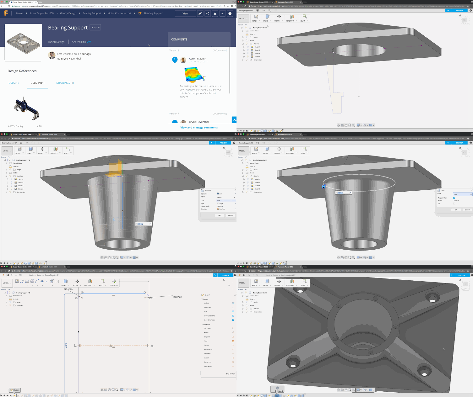
Ready to take this for a spin? Here’s how to do it. Log in via Fusion Team (used to be called A360), and you’ll first see all your projects. Double click on a project to enter it.
Create a new design in the web browser
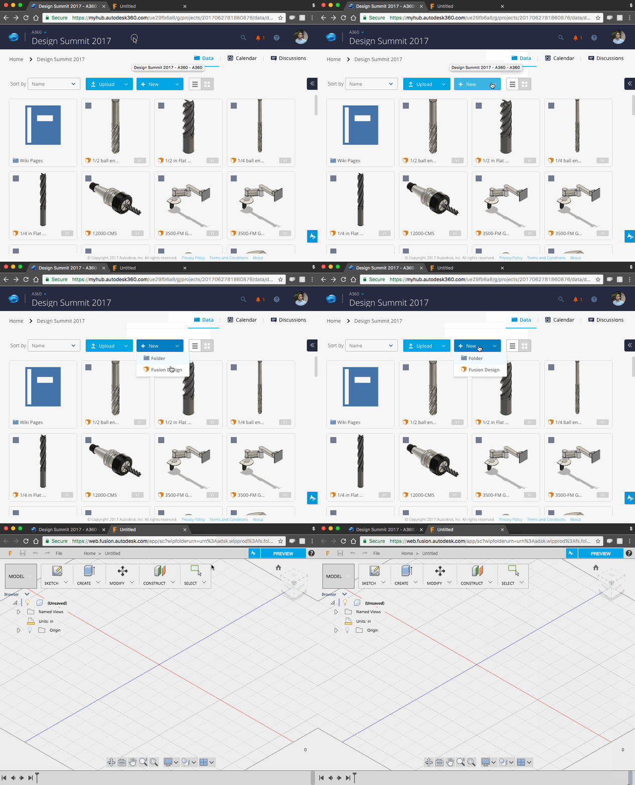
Navigate to the “New” button and select Fusion Design. This will open a new tab in your browser and load the design environment with an brand new document, ready for you design in.
Edit an existing design in the web browser
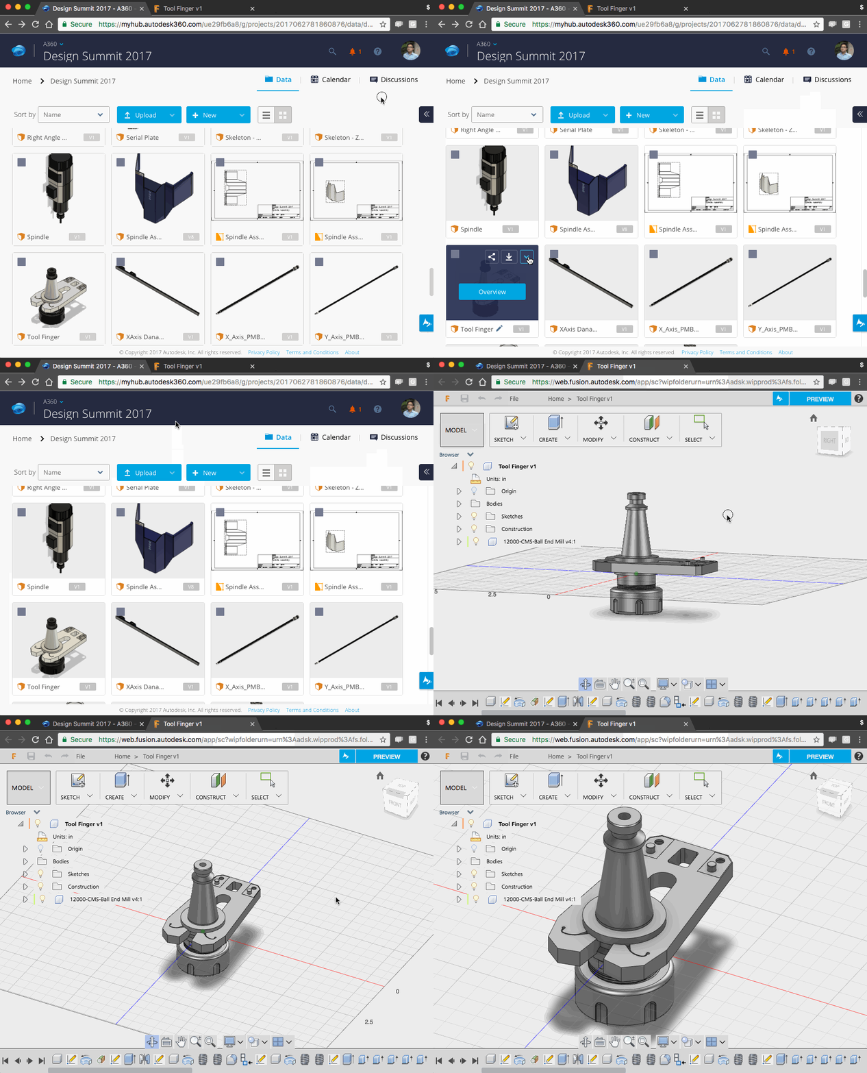
If there’s an existing design you’d like to edit, then hover over the design you want to edit and click on the arrow icon to see additional option. Select Edit in Browser and voila, you’re in!
A couple things to know:
- The current preview experience works best on Chrome browser.
- It will not work on mobile browsers yet.
- This is still developing functionality and not everything has parity with the desktop version of Fusion 360.
- Change your zoom behavior under the gear icon in the top right corner.

- This preview is constantly evolving as we build out more functionality, so don’t be alarmed if you see changes to the UI.
If you think that having a browser client will add value in your day-to-day design workflows, or are just curious about what you can do, we’d highly recommend you give this a whirl. We also a nicely documented Fusion 360 Browser FAQ on our preview forum that includes videos and how to get started for your reference.
As always, we’re looking for your feedback. What you tell us will directly impact how we improve the browser client experience, so let us know what you think!
New in Preview! ECAD/MCAD
If you’re designing products that include electrical components, then this is a preview functionality you will not want to pass up. Working with the Eagle team, we now have a new ECAD/MCAD experience that will allow you to design PCB layouts, leverage a shared component library between Fusion 360 and Eagle, and link components between the two so that updating changes call happen seamlessly. Learn all about the changes made to Eagle to support this new interoperability on The Nest.
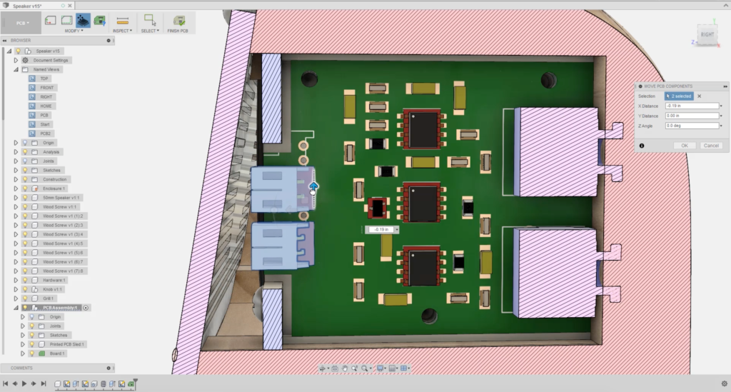
A new PCB Feature available in the preview section of your preferences. Turn it on and you’ll get access to a new tool under the Create drop-down menu called “Create PCB”. Please note that this preview will work best if you use in conjunction with Eagle. If you’re not already using Eagle, check it out here.

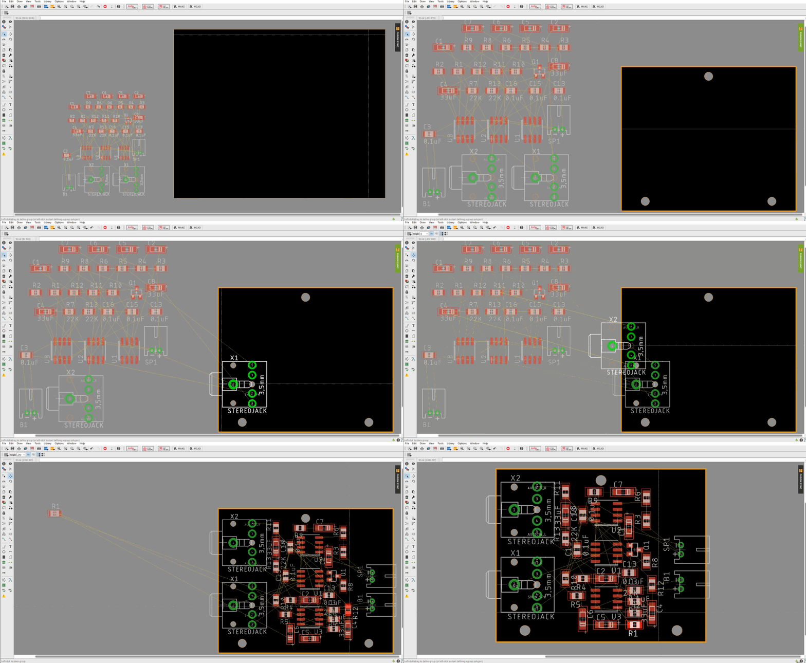
Create a board and pull from Eagle
Once selected, your toolbar will populate a number of new PCB-related tools. PCB board models can be created based on sketch profiles within Fusion 360. Once you have it created, you can go to Eagle and pull the board directly into your Eagle document for layout design and in a matter of seconds, the board will just appear like magic!

Once in Eagle, you can start designing the layout of all the components on the board.
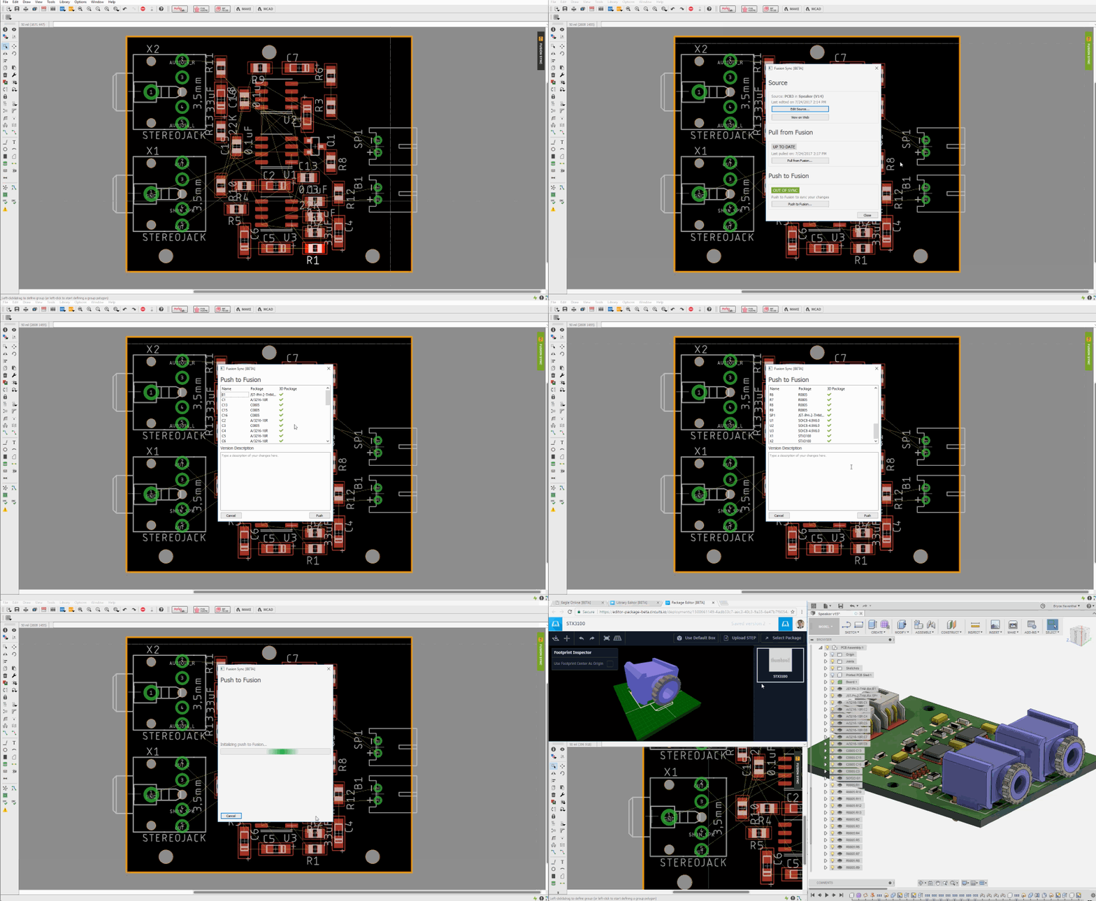
Push board layout back to Fusion 360
When the layout is finished, push it back to Fusion 360 and the components will show up as physical 3D models. Oh, it gets even better.
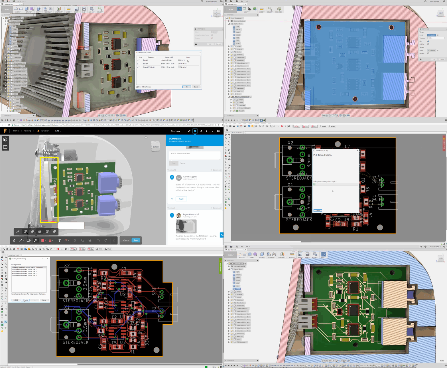
Edit board, reposition components, redesign layout, and repeat
If the components that came over from Eagle happen to be interfering with your design (as in it’s body overlapping another body), you can easily edit the board, reposition the component in Fusion 360, push the change over to Eagle, and reroute all the connections.
Let me just pause here and say: this is powerful. Not only is the data interoperability tremendously valuable, it also ensures that your electrical designers and mechanical engineers are working based on the same source data, reducing risks and potential mix-ups. If you want to learn more, I highly recommend you watch Bryce and Aaron’s What’s New Video, starting at the ECAD section. We believe this is just the beginning to something truly magnificent, and can’t wait to hear about your thoughts.
Always iterating. Never stop innovating.
As we wrap up this post, we’d like to take a moment and thank you, our amazing community, for all the feedback, encouragement, and relentless support. Also, we’d like to thank our expert elites for carrying the community with all your invaluable contributions, knowledge and passion about the software. We couldn’t have done it without you.
Cheers,
Keqing and the Fusion 360 team

