Partnerships are deeply engrained in Autodesk’s platform initiatives and are integral to our future strategy. These alliances aren’t just part of our ecosystem—they’re the heartbeat of our continuous innovation. Our vast partnership network allows us to become more than isolated point solutions for a world where connectivity and collaboration is the core to success.
We’re excited to share more details about our partnership with Cadence, which we announced at AU23 and put into action this year. Let’s dive into what this relationship looks like from a workflow perspective.

Fusion and Cadence: Integrated electromechanical design
Simply put, we’ve developed a seamless integration that synchronizes Cadence’s Printed Circuit Board (PCB) design tools with Autodesk Fusion. Any updates made in one system are automatically reflected in the other.
Our goal is to enable connected data to effortlessly enhance team collaboration. With Fusion, you can select the design tool of your choice and remain in sync, ensuring optimal productivity across all aspects of your project.

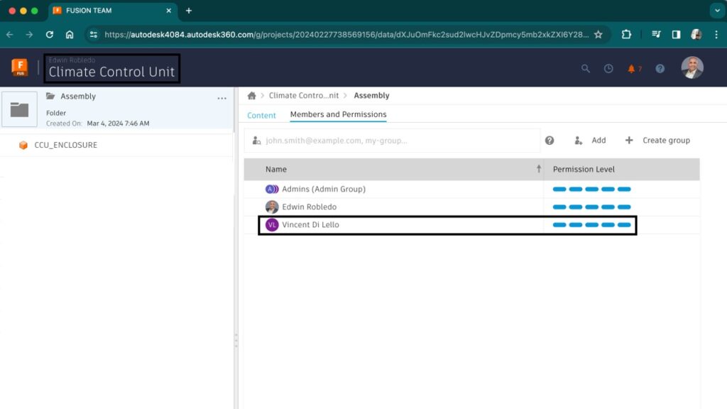
Collaboration becomes seamless by using our integrated data and the browser-based administration tool, Fusion Team. You can work effectively with third-party providers, contractors, or contract manufacturers—a crucial workflow for our operations. Within Fusion Team, it’s easy to add collaborators, such as those from Cadence, to a project. This project is a centralized repository for all manufacturing and CAD data, streamlining project management and enhancing teamwork.

Workflow example
In this exercise, we’re focusing on an enclosure that requires a board fitment. Four designated bosses indicate where the mounting hardware will be installed. Using these locations, we’ll initiate a sketch to proceed.
Next, we’ll employ Fusion’s 3D PCB tools to craft the board outline. These Fusion 3D tools facilitate the connection to Cadence, making it crucial to establish a 3D generic base for our subsequent work in Cadence.

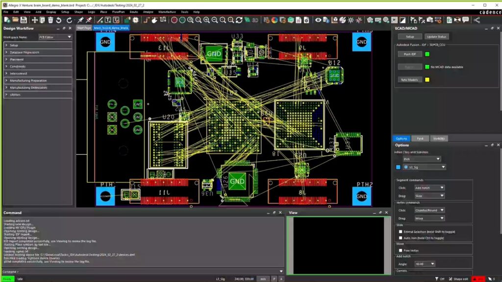
Next, my collaborator will access the MCAD collaboration tools in Allegro X. They begin by establishing a connection with the Autodesk connector in the setup phase. Once logged in, the connector will synchronize with the Fusion Team hub that I shared previously. After sync, we’ll select the climate control unit project we are developing. When the outline is loaded, we can then import the file into our working canvas.

At this point, we have the option to manually add components as necessary. However, for efficiency in this workflow, we can leverage scripting to automate the placement of our pre-defined components.
After loading the parts, we synchronize them with Autodesk Library.io, which will assign a unique identifier. Library.io acts as a bridge for our 3D PCB tools, ensuring that updates made in Cadence seamlessly integrate with Fusion. Additionally, it serves as a comprehensive parts library, allowing for consistent reference as new components are incorporated. We’ll notice that some components lack the Library.io identifier. In such cases, we can perform a sync to automatically tag these parts. Once they’re updated, we can promptly relay the file back to Fusion for further development.
Now that the design has been updated and synchronized with Library.io, and forwarded to Fusion, an alert will be generated in the Fusion 3D PCB workspace. This notification will inform you of the changes and offer the option to integrate them.

Subsequently, the 3D models will populate the PCB in the workspace and will be automatically arranged on our standard board. The following step involves embedding the 3D model of the PCB within the enclosure.
Upon placing the PCB into the enclosure, it becomes evident that there is an interference issue between the primary connector and the enclosure. This is due to the connector being slightly misaligned on the PCB.
Such misalignments are not uncommon in practice and, if not promptly addressed, can lead to expensive rework, as well as failures in prototyping and production processes.”

Fortunately, the synchronization of our data enables us to utilize Fusion’s Edit in Place feature. This powerful tool allows us to reposition the board accurately within the enclosure, even if changes occurred during the PCB design phase.
By employing the ‘move’ tool, I’ll adjust the connector by the necessary amount to ensure proper placement. It’s worth noting that the tab for the 3D PCB is marked with a lock icon, signifying that a modification has been made
After returning to the workspace, we can confidently accept these revisions. Subsequently, in Cadence, users will be alerted to the adjustments that have been implemented.
In Allegro X, we can check for updates on demand. When we look at the update status, we notice that a new file has been made available.

Upon opening the connector’s settings, we see it’s configured to pull updates automatically every 30 minutes. However, this setting can be overridden to pull updates at any time according to our needs.
When we incorporate the latest changes, it becomes apparent that the mounting holes have been modified. By integrating these changes into our design, we can observe on the left side that the component has been adjusted automatically.
Now, it’s time to import the remaining components. After this step, we will perform another synchronization to confirm that all parts are correctly aligned with Library.io. Any components that have not been previously added will now be transferred.
Following this process, the updated board will be pushed back to our workspace on the Fusion side, completing the cycle and ensuring both systems are in alignment. Once the data is pushed back to our system, we’ll receive an alert indicating that there are changes to be reviewed.

After we import the new components, you’ll notice that the components on both the top and bottom sides of the board have been updated accordingly.
To complete our process, we will integrate the PCB within the enclosure assembly into our larger seat assembly. It’s important to note that this incorporates the latest board version. This final step allows us to consolidate all the individual part changes into the comprehensive assembly, guaranteeing uniformity and ensuring that the components are production-ready.

Integrated electromechanical design at your fingertips
Our commitment at Autodesk is to enhance your design and make workflow with innovative, easy-to-deploy, professional-grade tools. And Fusion’s goal is to foster teamwork, responsiveness to changes, and efficiency regardless of industry focus.
This article has demonstrated the power of Cadence and Fusion’s integrated workflow for electromechanical design. Our tailored approach refines component design, fast-tracks product development, and mitigates errors while boosting throughput. By implementing this specialized strategy, electronics engineers are able to improve component design, expedite product development, and reduce errors, thereby enhancing overall output.