This post is also available in: Italiano (Italian) 日本語 (Japanese)
The past two Fusion updates have included massive added value to the Turning and Turn/Mill functionality, and we’re thrilled to continue delivering even more functionality in this area. We’ve been focusing on tackling the most common problems users face with threading and have made some great additions to increase the overall efficiency in generating cutting paths for turning.
These updates empower you to run your machines with a greater level of effectiveness. Let’s take a deep dive into what we’ve recently added in this area, from threading improvements to a new dedicated Bar Pull strategy.
Turning threading improvements
Enhanced control
Threading tools, which are available in various shapes and sizes, play a crucial role in determining the optimal cutting depths for the toolpath. We’ve now opened up the Turning Threading tooling definition to allow you to control the precise cutting insert for a Threading Tool and Thread Profile Angle. You’re no longer limited to only a 60-degree flank angle on inserts!
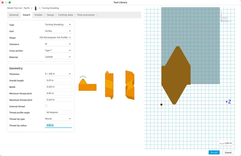
We’ve also added explicit control over the tip condition of the tool. Thread tip type determines if the thread shape comes to a rounded tip, a sharp point, or a truncated tip combined with the control now over Thread tip radius or Thread tip width. Specifying the tip type provides you with an elevated level of control over the tool precision, enhancing your ability to generate better toolpaths and more accurate simulation experience.
These new definitions also open many new possibilities for supporting new thread insert types like Trapezoidal, ACME, and Whitworth, along with Pipe couplings (DIN 405 Round).
First pass
Threading tools typically feature a small nose radius. It’s the smallest point on the insert and the most likely to break under the machining pressure of a threading operation.
Most threading applications will have a set number of passes to optimize the performance of the insert. However, the optimal number of passes would occasionally yield a shallow initial cut depth, leading to excessive vibration, or conversely, an aggressive initial cut depth, posing a challenge to the tool’s integrity.
Therefore, the addition of a First Pass for threading has been added to the Turn Threading Strategy to allow you to override the default value. Keep in mind that this will not let you independently separate the number of passes to complete a thread and the initial depth of cut to start the thread.
Expanded options
The last enhancement to the workflow improvement to Threading in this release is the expanded array of options available to define thread length.
Previously, the threading process operated independently from Fusion’s usual paradigm, primarily relying on selecting a cylinder to determine the thread length. While effective for threads encompassing the entire cylinder, users encountered difficulties when needing to adjust the thread length, grappling with identifying the appropriate offset values and their origins to achieve a precise thread length.
Now you will recognize the same Front & Back confinements that we offer in every other strategy. Along with the ability to associatively pick edges, model references, or stock references for setting the start and end of their threads.
Turning face mode
As the backdrop for the next set of turning toolpath improvements, I attended the last IMTS and watched over the shoulder of an Autodesk application engineer while he demonstrated Fusion’s turning capabilities.
The prospective customer outlined their desired outcome, which involved using a face grooving tool to machine a seal groove on the part’s face. I watched as the application engineer struggled to achieve the desired result. The confusion started with choosing between Outside Grooving or Inside Grooving and not knowing for sure which one would allow the use of a Face Grooving tool to machine that specific section of the model.
This immediately sparked my interest in questioning why this process wasn’t streamlined. So, we developed a new turning mode exclusively tailored for machining the face of a part. Now with a dedicated Turning Mode for Face for our Grooving and Profiling strategies, this should be very discoverable to everyone.
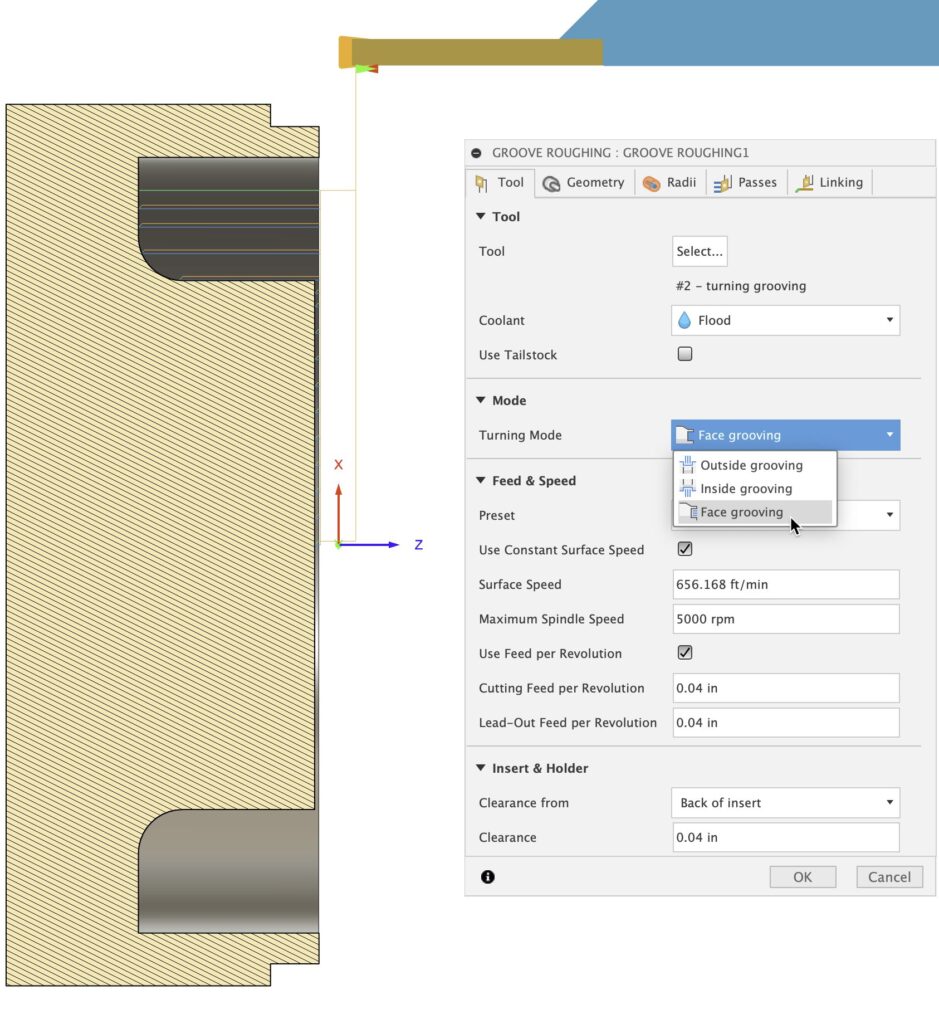
This new mode also allows us to give better, safer retract moves which will prioritize moving in Z before moving in X. The direction of the cut also changes from Front to Back, Back to Front to Inside to Out, or Outside to In.
In some instances, machinable features defy categorization of Outside, Inside, or Face regions. This is particularly evident in parts with more organic shapes, especially in their frontal areas.
For that reason, when using the Outside Profile mode, we will allow machining of ‘disconnected regions’ that gray area between Outside, Inside, and Face. The example below shows a specific example where regionalizing the toolpath would have resulted in the need for two, or maybe three disconnected toolpaths to achieve the full profile.
Chucks and fixtures
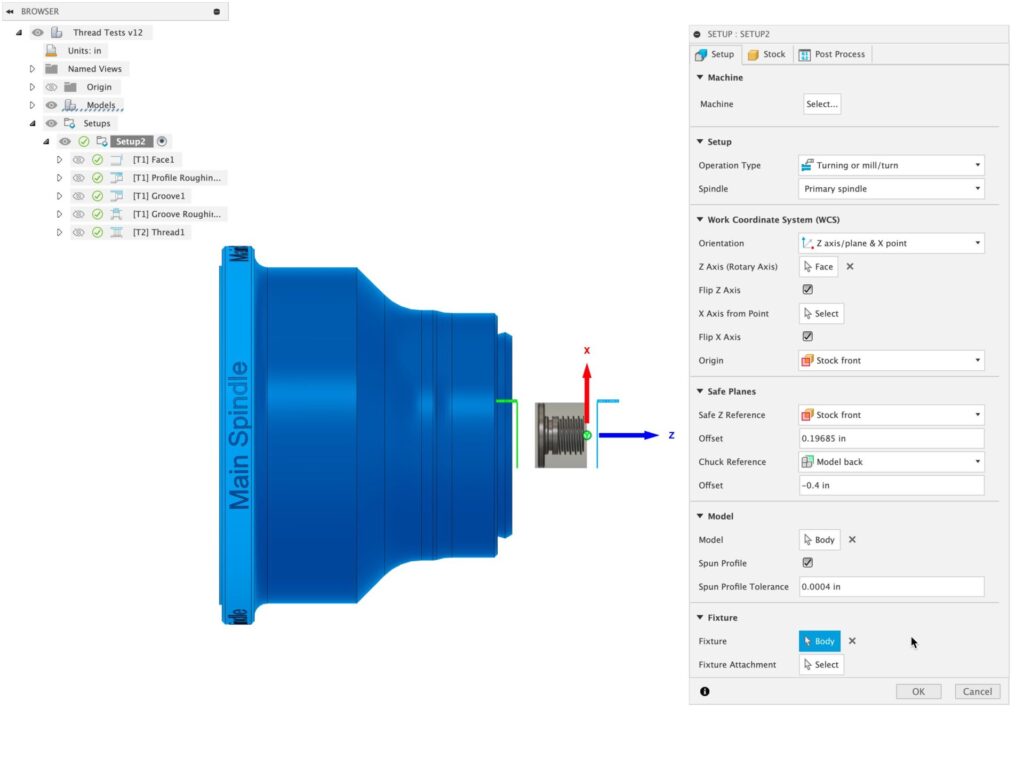
This release also sees the addition of Fixtures in a Turn/Mill set-up and some reorganization of where Chuck reference goes. The main reason for this change is for future consideration. We’re hoping to deliver work in the future to automatically avoid fixtures in toolpaths (and we really wanted TurnMill users to benefit from this enhancement when it’s ready for release). This brings more consistency between Milling & Turning set-ups and allows us to share future enhancements.
The Chuck Reference feature remains accessible and has been moved to the Safe Planes section. You can still define the Chuck Plane using familiar options, but it is now enhanced with the capability to reference the Fixture if it has been selected as the work-holding method.
New Bar Pull strategy
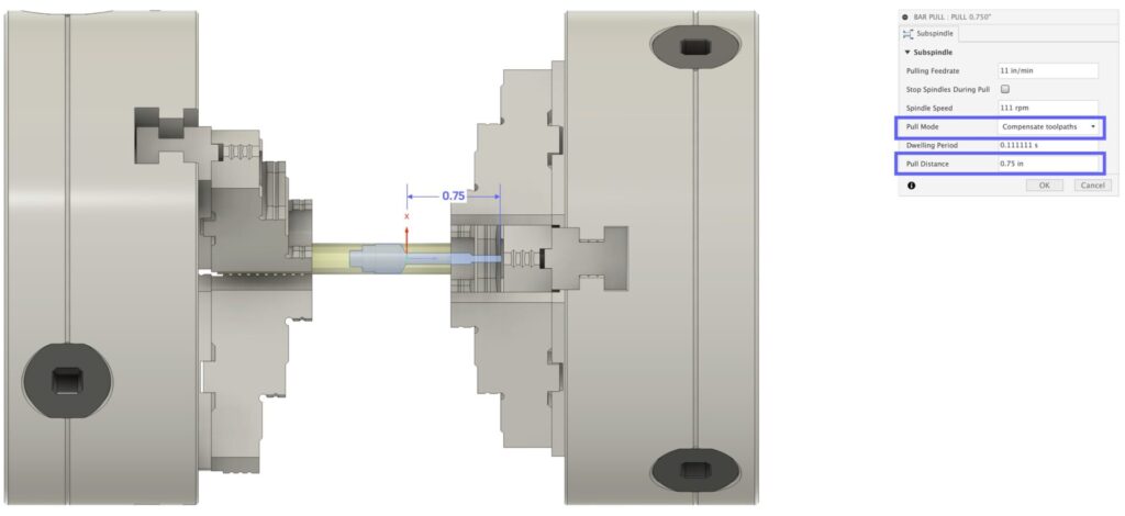
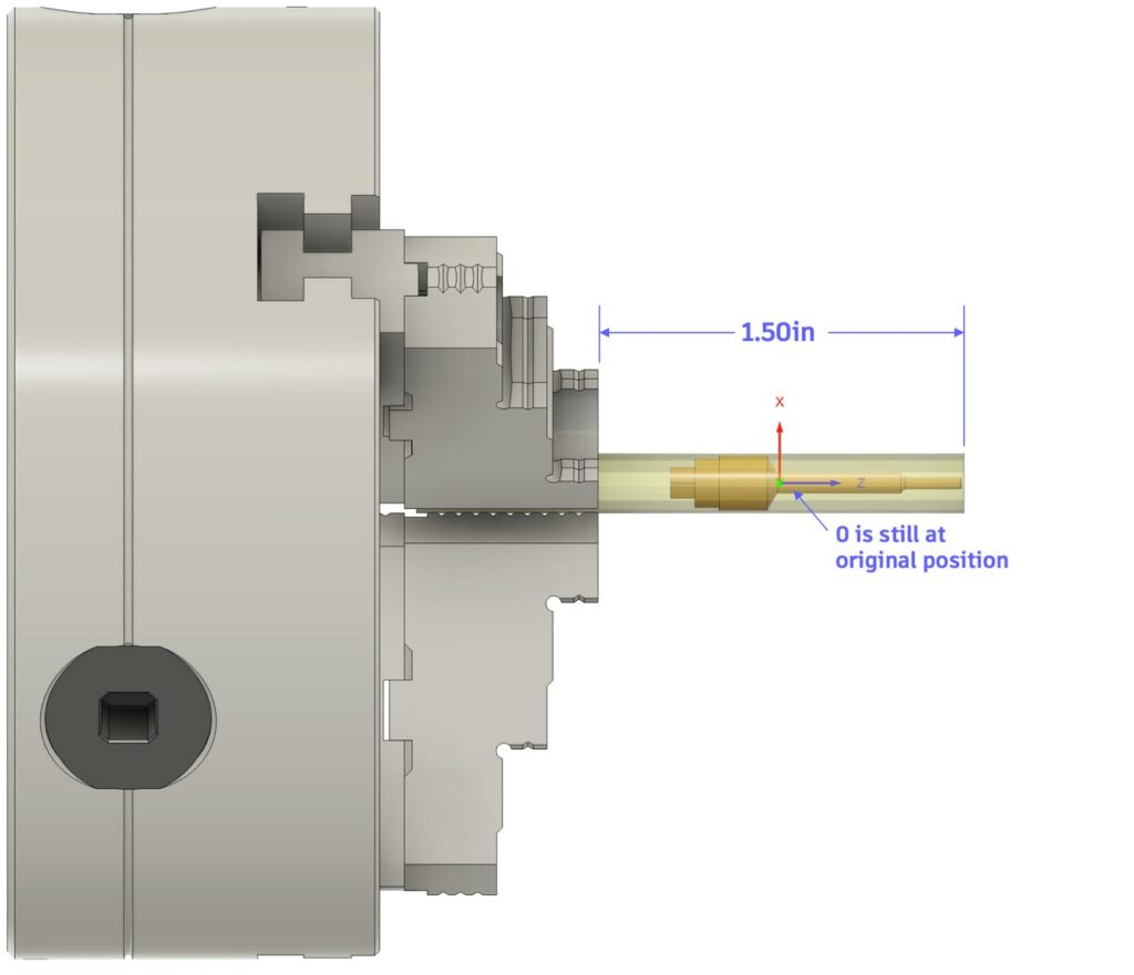
The last big enhancement for those of you programming dual spindle machines is the addition of a dedicated Bar Pull strategy. This new operation offers you two forms of a pull bar, one where the bar is pulled out a specified distance and G54 remains the set-up but each toolpath after the bull occurs is compensated by the pull distance.
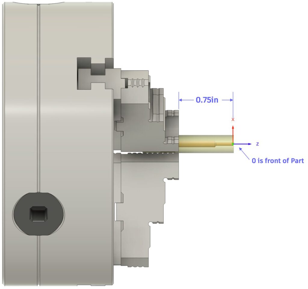
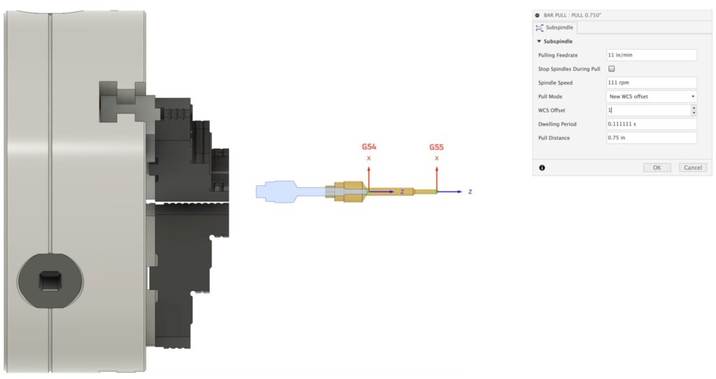
Option two is to perform a pull operation but create a New WCS for the post-pull operations.
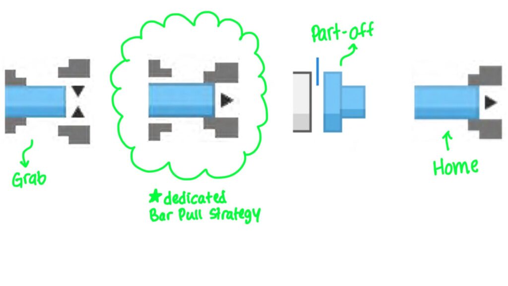
The addition of this operation will remove a lot of the ambiguity as to how to perform a proper cut-off procedure in Fusion for your machine and complete all the pieces for the puzzle needed.
Other turning enhancements
Other toolpath enhancements in this release include a New Default chaining type for the Turning Toolpath when using Model Override and improved linking between the cutting path, the start point, and the end point of the toolpath for Profiling and Grooving strategies.
Additionally, we now ensure that a lead to cut Stock is checked in turning profile finishing operations. If a lead out traditionally would have gouged the model instead of not creating a lead out at all, it will now be created with a modified angle to prevent a gouge with the model. This behavior will make it consistent with the creation of a lead-in.
Stay tuned
Keep an eye out for more turning enhancements, as we’re excited about improving this workflow for you!