What Are the Best Settings for Smoothing and Tolerance?
Spoiler alert: there aren’t any! I often get asked what the best smoothing and tolerance settings are, and if smoothing and tolerance even really matters. These are great questions, and I’d love to provide some concrete facts that will solve this problem for all eternity, but it’s not that simple. The truth is, there are no “best” settings out there. The only way to arrive at “best” is to understand the relationship between your CAD, CAM and machining tools and how they work together.

I realized this problem was worth digging into when a friend called to troubleshoot surface finish problems he was having. He kept asking, “what smoothing and tolerance settings should I be using?” but how was I supposed to know? I didn’t know his CNC machine as intimately as he did. He had all of the answers right in front of him, he just wasn’t seeing it. He needed to get to know his machine more intimately first before he could answer that question. Here’s what he was missing:
Know Your Code Processing Constraints
Every machine is designed differently and can process a specific amount of code blocks per second, called BPS. There’s also the consideration of how far a machine can “look ahead” at its upcoming code blocks to control acceleration and deceleration. Depending on the complexity of part geometry, you can have a machine that gets bogged down trying to look too far ahead at code blocks and it just can’t process as quickly as it needs to. In this situation there’s a clear limitation between the machine’s available memory and its ability to process code. Here are some guidelines to keep in mind about code processing:
- Machines that can process a lot of code should have their G-Code outputted in tiny segments. This will often produce smoother arc movements and higher quality parts.
- Machines that are limited in their code processing will work better with G2 and G3 G-Code in combination with tolerance and smoothing settings.
How much does code processing affect the cycle time to produce a part? We’ve got a Haas VF2SS at the Autodesk Pier 9 Workshop that I tinkered with for this article. By turning on the Haas High Speed Machine setting, which optimizes code processing, we completed a cycle in 8 minutes that took 12 minutes without the setting on. Code processing matters, and it differs between machines. Know the limitations of yours.
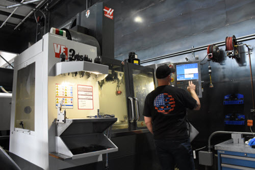
Know Your High Speed Machining & Smoothing Constraints
You might see this setting named differently depending on your machine, but it all comes down to balancing acceleration and deceleration with accuracy and rounding corners. A good way to visualize how high speed machining and smoothing works is with a race track. If you make the race track lane wider, than a vehicles can go faster through corners without needing to decelerate.
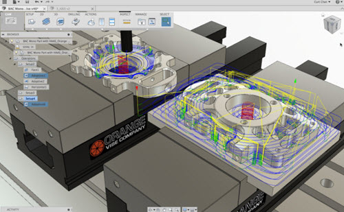
This same principle holds true for your CNC machine. If the path of travel has a lower tolerance requirement then it can move around its toolpath faster. The settings for high speed machining and smoothing are generally controllable within the G-Code and can have a tremendous impact on part quality and cycle time.
Know Your CAD Part Design Constraints
There are a variety of ways to get a desired line shape in your CAD software, whether that’s using splines or tangent arcs. But consider this, using tangent arcs or splines will affect how much code your CNC machine has to process. If your machine can only process a limited amount of code then you’ll get the best cycle times using tangent arcs.
What You Really Want to Know
The basic constraints discussed above work hand-in-hand with smoothing and tolerance settings. Without considering the processing and high speed capabilities of your machine then you’ll never be able to find the “best” smoothing and tolerance settings. Remember, every machine performs differently. Now that we have the basic concepts covered, let’s talk about what you’re actually here for, tolerance and smoothing settings.
CAM Tolerance Settings
Here’s the one thing you need to know about tolerance – how accurately your toolpath matches its desired shape will depend on the number of line segments used. A lower tolerance will produce smaller line segments, which will in turn more closely match the surface you designed. There’s often the urge to set tolerance values at the lowest possible value, but hold on. As we discussed above, you need to know your tools. Depending on your machine, a lower tolerance will generally lead to:
- Longer tool path calculation times
- Larger G-Code program sizes
- Shorter line segments
Before ever setting your tolerance value, really consider whether your machine will better handle tangent arcs or splines. A CAD model designed with lines and arcs will generate G1 moves for straight lines and G2/G3 moves for the arcs, and will use less line segments. The same model designed with splines will require the CAM system to approximate surfaces and linearize them, leading to many short line segments to approximate the same surface. Again, it all comes down to what your machine can realistically handle.
CAM Smoothing Settings
Smoothing and tolerance have a direct relationship with one another. By turning smoothing on, it removes any excess points from the toolpath within a given tolerance. It also replaces line segments with tangent arcs where possible. At its core, smoothing is all about reducing the code size of your project. Here’s what you need to know about smoothing – turn it on for machines with limited code processing and look ahead capabilities. This will reduce the program file size, improve code processing/look ahead capabilities, and overall result in better part quality and cycle time.
Tolerance and Smoothing in Action
Over at the Autodesk Pier 9 workshop I put these guidelines to the test on our Haas VF2SS machine. First, I designed a few parts using splines. I could have also used tangent arcs, but both produced similar results in this instance.
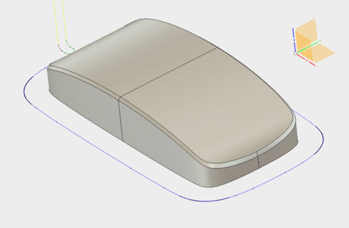
For the first trial run, I set a tolerance value at .0005” and turned the Haas High Speed Machining off. The part took 12 minutes complete and had a very poor finish.
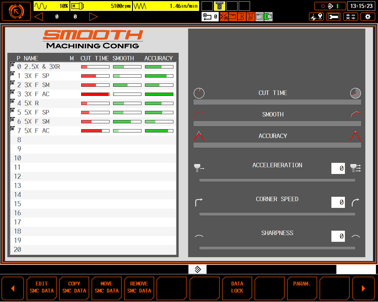
For the second trial run, I kept the same tolerance value at .0005” and turned the High Speed Machining on. This part took 8 minutes to complete with a better finish, but it still wasn’t where I wanted it to be. Keep in mind, at this point all we’re changing is the look ahead capabilities of the machine with the High Speed Machining Setting. To really get a high quality finish we need to try smoothing.
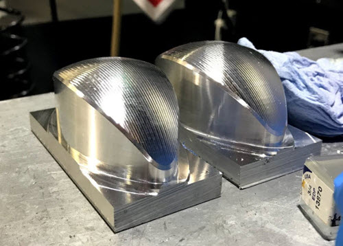 For the final trial run we kept our tolerance value and High Speed Machining settings as is but turned on smoothing for each toolpath with a .0005” value. Not only did we decrease cycle time down to 6 minutes, but the finish was beautiful!
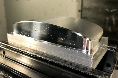
When In Doubt, Smooth It Out
During my history of machining I’ve seen professional-grade parts produced on hobby machines, and the worst looking parts produced on the best machines money can buy. It’s clearly not the machine that’s the sole deciding factor here for quality. So what is? You! It all about understanding your tools and how they all work together to produce high quality parts. You aren’t designing CAD parts in isolation. The complexity of your CAD design has a direct affect on your CNC machining and its processing constraints. As the saying goes, the devil is all in the details. Know the details of your tools and tolerance/smoothing settings will soon be an afterthought. Ready to perfect your smoothing and tolerance settings? Try Fusion 360 for free today!