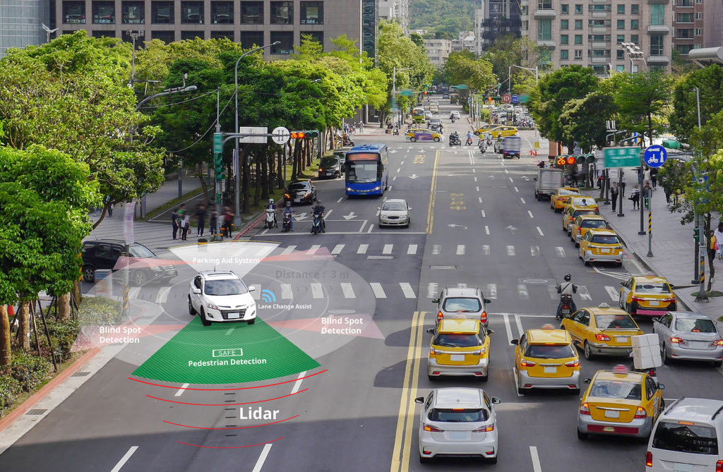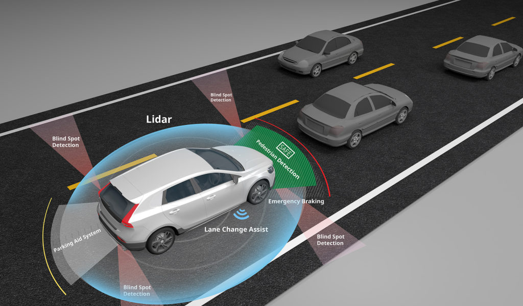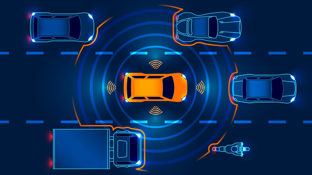
Advancements in LiDAR product design will likely become a key factor in separating connected and autonomous vehicles (CAVs) from the competition. Over the past few years, major players including Apple, Google, and Tesla have deployed test fleets across the United States. The industry will only continue to get more competitive, and more use cases for the technology will surely arrive. With an expected market valuation of roughly $556.67 million by 2026, CAV manufacturers could encounter numerous challenges in lockstep with scaled production — especially as optimization and cost efficiency become paramount.
Accordingly, the complex sensors, laser technology, and electrical systems within high-resolution LiDAR units — including those within autonomous vehicles and even mobile devices — must function reliably and harmoniously, as safe operation is immensely important. Thankfully, CAD/CAM have made (and will continue to make) LiDAR innovation possible moving forward.
Form Factor Considerations

The earliest LiDAR systems were large in size, weighing upwards of 45kg and spanning 76cm in diameter. Hardware consolidation has since made these systems progressively more compact. Velodyne’s LiDAR PUCK measures a diminutive 7.2cm x 10.3cm. The PUCK and PUCK Lite weigh 830g and 590g, respectively, without any notable differences between them. This suggests two things:
- Designers can put a large amount of sensory technology into one package without compromising functionality and while still remaining high quality.
- Materials can be adapted to fit weight-sensitive applications.
Velodyne certainly isn’t the only company in the LiDAR space. Companies like IBEO and Luminar have introduced models that negate that footprint-capability tradeoff. So, how do manufacturers get there? Likely through the use of CAD and CAM software.
Designing the Perfect Enclosure
A LiDAR system’s overall design asks a few things of its enclosure. It must be strong to ward off scratching and chipping from road debris (via event simulation), relatively lightweight, and accommodating to any requisite components. We might consider dimensional requirements. With CAD models, it’s possible to arrange the following components in a proposed layout, prior to finalization:
- Fixed or surround-view sensors
- An optically-safe laser
- Connection ports for power and data set transfer
- GPS units, in some cases
- A regulated power supply unit
3D modeling gives teams the ability to visualize how these components could fit together. These 3D models are typically contained within a workspace — ideally, a cloud-based design canvas where teams manipulate products during development. CAD software, which enhances precision and experimentation, allows teams to tweak design parameters on the fly, mixing and matching dimensions, layouts, shaping, and more. These are easily accessible through drop-down menus, function ribbons, and input fields. Fusion 360’s cloud platform enables anyone on a team to access shared CAD files from anywhere, which maximizes collaboration potential, increases visualization across remote teams, and eases strain on workflows.
Rectangular and cylindrical LiDAR products are very common on the market. Consequently, these systems operate using fixed or surround-view sensors. Fixed sensors are embeddable and thus miniaturized compared to their surrounding counterparts. That component sizing is impactful on unit design — the sensor’s proximity to the PCB and other electronics will partly determine the final product’s measurements.
Manufacturing Constraints

There are two schools of thought in the autonomous driving world: design for scale or design for specialized applications. Many a LiDAR projects have arisen from a Defense Advanced Research Projects Agency (DARPA) competition or research collaboration, which aren’t necessarily cost limited.
However, commercialized designs are aimed at widespread adoption. Production at a broader scale introduces margins, materials constraints, and supply chain quirks into the mix, and manufacturers must balance costs with availability to generate profits and meet demand. Thankfully, CAM software allows teams to input their unique constraints. Design prototypes are automatically validated against this checklist to prevent conflicts. The right application ensures that manufacturing is sustainable in the long run.
Thermal Considerations
LiDAR systems emit laser energy and inherently generate heat while they are active, due in part, to the simultaneous operation of sensors and supplemental circuitry. Companies combat excessive heating through power efficiency. LiDAR units, like any other connected electronic device, draw a current while working. A linear relationship exists between this wattage demand and heat generation, and minimizing power consumption at load is essential, which is why efficient systems tend to be thermally performant.
Naturally, there are other factors that come into play, such as the number of components operating in tandem and their peak and average temperatures. Fortunately, some CAD programs offer insights into thermal performance on a per-component basis. This information helps engineers determine if component swaps or reconfigurations are needed. Thermal mapping simulations are available, which show where heat is congregating within the device over time at different workloads — hotspots may be indicative of inadequate designs.
Another key factor is enclosure design. What the product’s housing is made of, how well those materials conduct heat, and whether or not it provides enough breathing room for heat dissipation are all important factors to consider. CAD software may also demonstrate how variable airflow contributes to cooling and reliability. These LiDAR units are affixed to moving vehicles, after all.
Data Capture and Product Validation

Ongoing designs rely upon testing data, which LiDAR sensors capture in large quantites. LiDAR laser mapping utilizes an array of projected dots; these paint a picture of the surrounding environment, including people, vehicles, buildings, and other physical landmarks. The onboard system will evaluate these “point clouds” in real-time to promote safe operation. Engineers can take this data and determine how effectively the product in working under simulated, real-world conditions.
Accordingly, this data must exist in a readable format to both humans and applications. Within Autodesk, it’s packed into an RCS file. RCP files (representing projects) can then reference multiple RCS files. Designers can attach this information to drawings, promoting smarter iterations. Weaknesses are identified, strengths are noted, and product refinement commences until production readiness is achieved.
An Autonomous Future

As CAVs grow increasingly ubiquitous, manufacturers will likely begin devising long-term plans to support that boom. 3D CAD and CAM applications like Fusion 360 are uniquely suited to quell uncertainties and provide objective solutions. From design to sustained production, these tools will be workhorses for stakeholders across the automotive industry. There are numerous approaches to LiDAR implementation, and while each company will champion its methods, computer-aided processes will help make all visions a reality.
Try Fusion 360 — the only complete CAD, CAM, CAE, and PCB tool — today.
