“There are no beautiful surfaces, without a terrible depth.” – Friedrich Nietzsche
This article is intended for industrial designers and is not reflective of Alias workflows. If you are interested in deeper Class A tools, please check out our friends over at Alias.
Class A geometry was originally an automotive industry term that refers to a surface, or series of surfaces, that have curvature and tangency alignment. It’s an ideal method when working on the aesthetics of cars, but I’m here to tell you that in today’s day and age, you’re probably using class A more than you need to. (Put the pitchforks down, I see you in the comment section primed for a rant about the glory of class A geometry, but I assure you it isn’t under any threat.)
In all honesty, I’ve been avoiding writing this blog post for a while. In CAD terms, I’m an old dog. I’ve been doing this since I was 16 years old, and I come from a background that is obsessed with geometric perfection. In the past ten years of my life as a professional, however, I have only used class A once in a real-world situation, and that was last year while working on the Volkswagen project.

Credit: Volkswagen.
Class A geometry has become a benchmark that industrial designers use to determine if their tool is good enough to use, but what a lot of people fail to remember is that in most manufacturing situations, your class A surface won’t make it into the physical world. We simply don’t tool things for that level of tolerance.
“But what about rendering!” Well, let’s be real: editing images is faster, and most clients prioritize delivery time over that last percentage of perfection. Even if you are a CAD master, it only takes a beginner level of skill in Photoshop to edit your renders to get that pixel-perfect look. Unless you work in an industry or on products that will explicitly use class A geometries at a physical scale (such as a car body,) there is little need to produce class A geometry.
For those times when class A geometry is necessary for a project, however, let’s dive into how we do it using Fusion 360.
Prerequisites
First, let’s take a look at some essential tools you will need to know at least at a fundamental level before getting started.
- Parametric modeling
- Find a primer here.
- 3D sketching
- At least have a fundamental understanding of how to use this environment to create 3D sketches.
- Surface modeling
- Check out classes here.
- Silhouette split
- Silhouette split is located in the toolbar. It takes any construction plane that intersects a body and then gives you the edges at the outermost point of that object based on the orientation of your construction plane.
- Networking
- If you’ve used tools like Alias, or other surfacing modeling tools, chances are you’re familiar with the principle of network surfaces. In Fusion 360, the process of producing network surfaces is already built into other tools and is not explicitly called out. We call this “horizon modeling.”
- Horizon modeling:
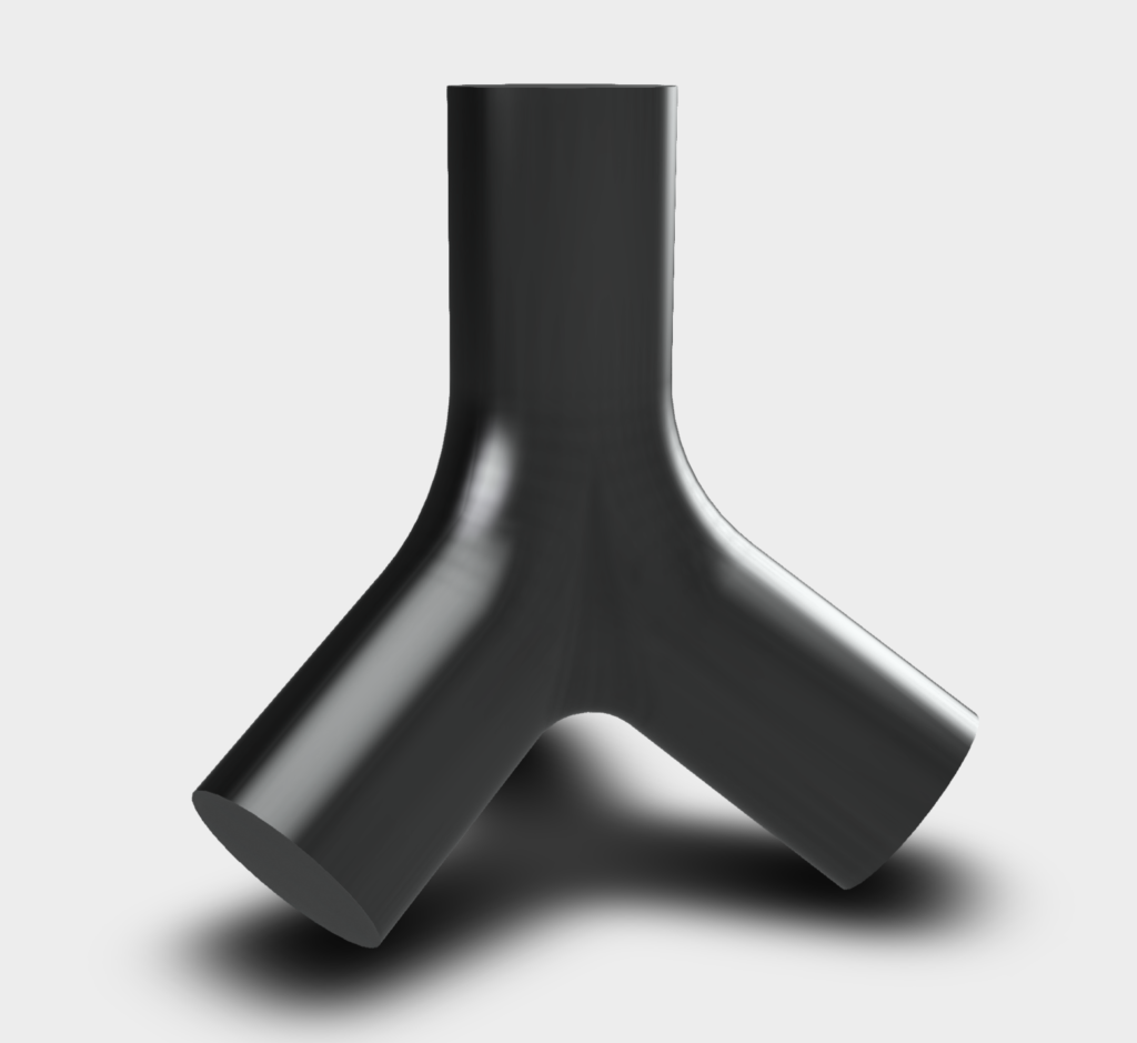
- In the example of the tetrapod, or any other class A geometry problem, the most essential element that makes up the surface are the edges. Making sure normals and tangents are in place ensures a class A geometry. As a result, within the Fusion 360 surface model space, we use a series of sketch processes and surface patches to ensure that you can always net a class A geometry.
- The crux of horizon modeling is implied tangencies/curves. By defining guides that are perpendicular to your core geometry planes, you can create a series of 3D plane surfaces that can be used as references. Horizon modeling adds a level of complexity and nuance that you cannot get from ribbon modeling and, in turn, unlocks a more precise, controllable way to generate class A geometries.
By producing a series of ribbons, you’re able to use the model edges to loft between surfaces and then use the curvature options to get to a class A geometry quickly. However, as anyone who has ever produced class A geometries can tell you, this often doesn’t work, and you will need more options. This is where horizon modeling expands over it’s older brother, ribbon modeling.
Exercise 1: The First Foray
We previously wrote a general blog post about how to use various tools in Fusion 360 to achieve class A models. Now, we’re going to outline a first exercise you can try that uses the tetrapod Chad Lockheart produced for us as a case study.
First, let’s look at how to produce a solid object from the surface space and exactly how the loft tools we mentioned above work.
1. For this first exercise, begin by setting up three sketch planes with ellipses on them and loft through to achieve the geometry. This parametric is, of course, based on what definitions are already in place. As you use the timeline, you can move any of those sketches in 3D space to rebuild the loft.
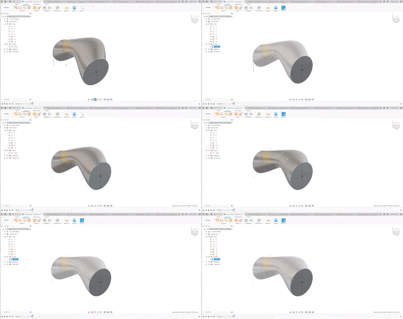
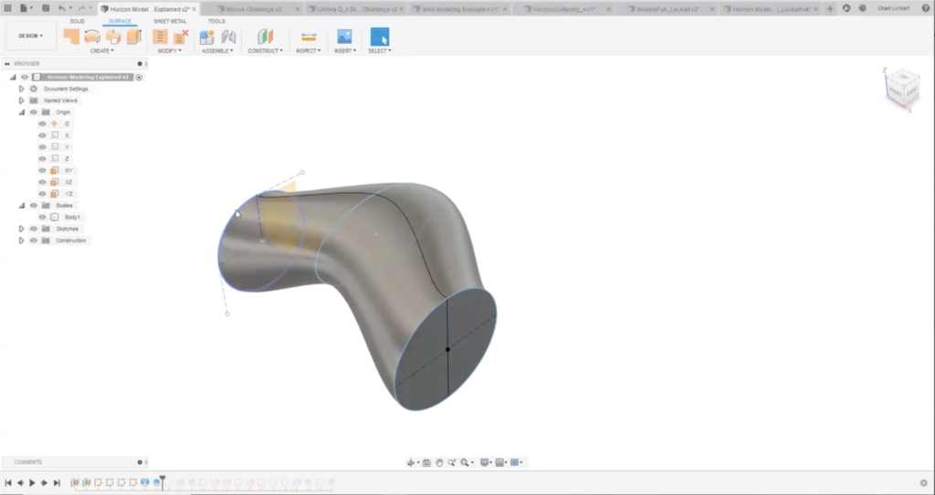
2. These new silhouette splits can then be used to create planes that will be used as references for the creation of ribbons. These ribbons are achieved through Create » Extrude and will give you 3D edges that can be used to produce reference ribbons.
3. It is important to make sure you create projected 3D sketches for each of the control edges you produce. If you try to extrude an edge in the surface space, you will see that your extruded surfaces are not tangent. This will cause issues down the line. Handy tip: when extruding your ribbons, make them all the same distance, so they’re easily identifiable later on.
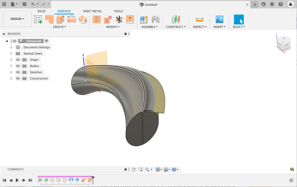
Womp, womp. This is an example of what the ribbon extrusions shouldn’t look like.
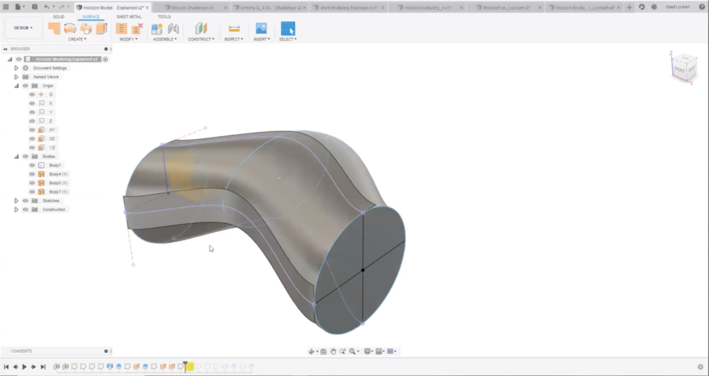
That’s more like it!
4. As you loft through these edges, you’ll notice that when you select a tangent or curvature profile for them, your compound-complex surface can produce the curvature to the surface you would expect.
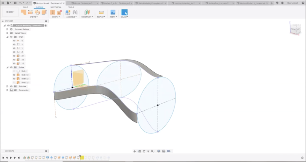
Ribbons and sketches, without the original loft.
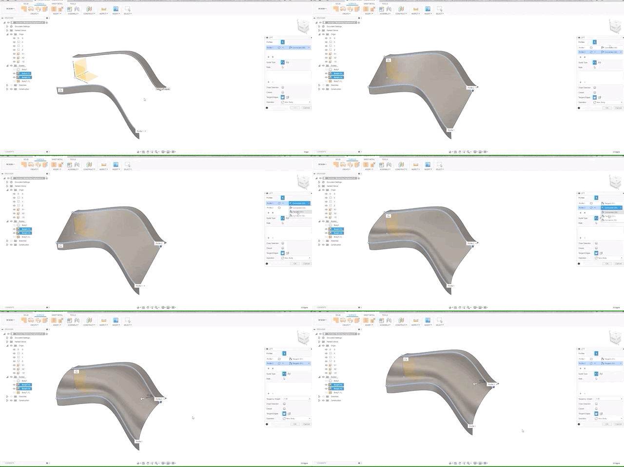
The above exercise is just the first step. This method only works for a very specific kind of surface transition, and it gives you no control over how the surface behaves between the beginning and end of the loft in the V direction. On that note, let’s move on to Exercise 2.
Exercise 2: The Meaty Bit
Get ready because it’s about to get way harder. This exercise is more complex, as it outlines how to handle the transitions between multiple parts that meet one another.
1. Using the same tetrapod, we’ve started by defining our origin and the angle that our three cylinders will take. We’ve set up sketches below that include the definitions of distance from the origin and where the circles that will become our cylinders are extruded from. We also have an additional point in place so we can extrude to that height, making the lengths of each of these extrusions (and the total volume of the transition area) parametric. As before, you’ll want to use a silhouette split to find the horizon line you will be using for your transitions later.
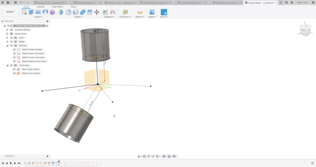
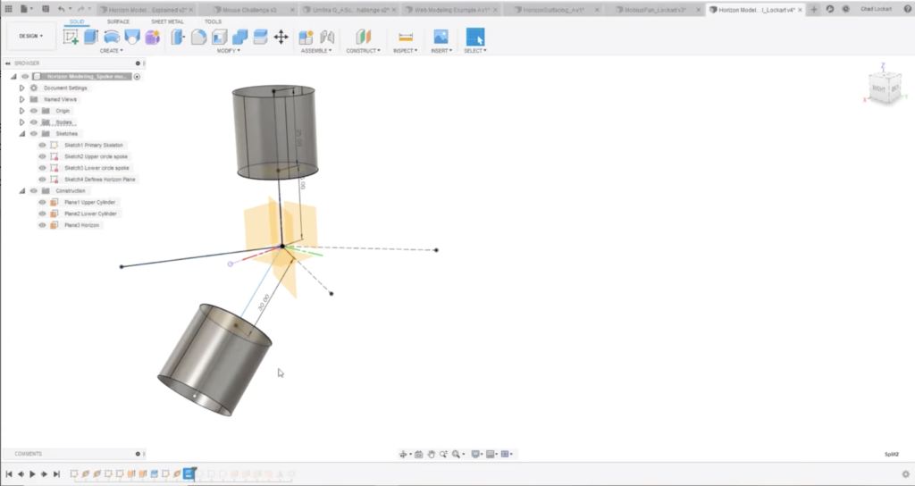
Construction plane along the model lines to create the horizon split where the two surfaces will meet.
2. Next, we need to identify where our more complex horizons will be. In this case, we’re identifying where our horizontal horizons will be for the two other spokes of this tetrapod. In the image below, you can see we have some construction lines and a defined line that we will use during the next stage.
3. The plane we have put in here is normal to the angle of the spoke. This is achieved by applying a plane along the path to this model line shown below, and setting it to be within the origin of what we’re making. This construction line is now used to create the next silhouette split, that will be in between the spokes being made. This will enable us to create a model line where the transitions meet once again.
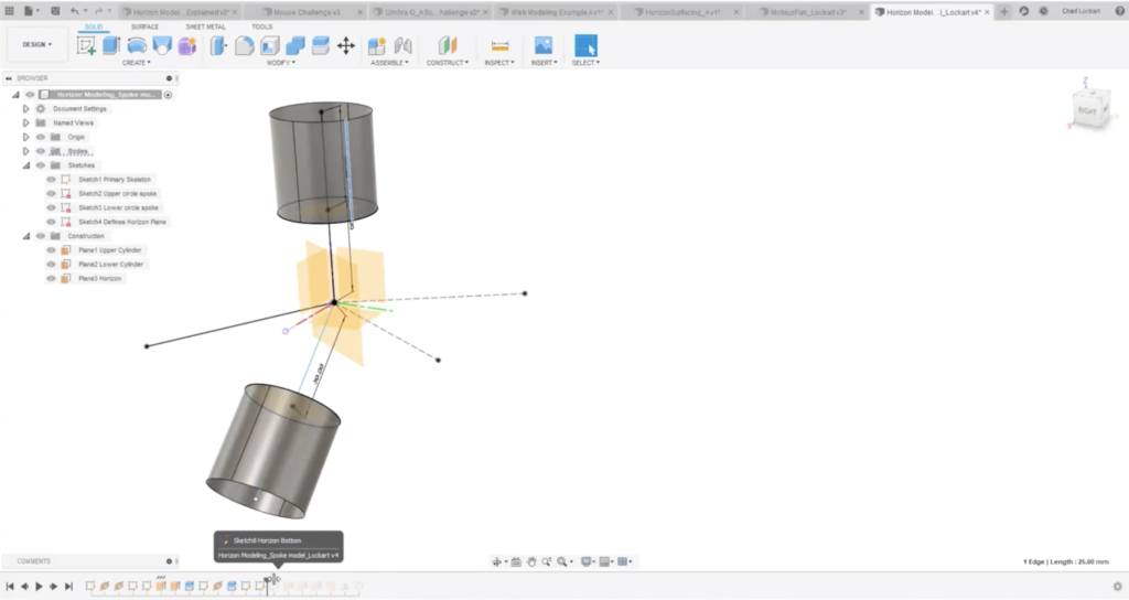
4. At this stage, we can start to insert some of the model lines that will create our desired geometry. When applying your splines or cv curves, it’s essential to make sure the endpoints are collinear with the model edge they are meeting to ensure that the surface continuity will behave how you want it to. In our case, we have used a two-point spline with collinear endpoints. Should we wish to change how the geometry behaves over time, changing the lengths of the splint control points will enable us to have simple and continuous control over the curvature.
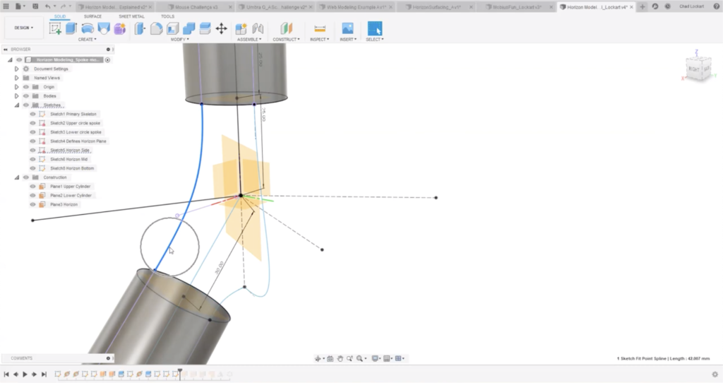
The three sketch lines you see in this image are all you need to achieve the geometry with perfect transitions.
5. We’ll go ahead and extrude some ribbons, making sure they are perpendicular to our sketch lines. At this stage, we’ll need to make sure that our parts are tangential. If we apply a patch to these edges, we are quickly able to determine if that is the case.
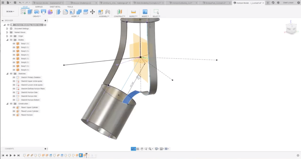
6. You’re in the home stretch!
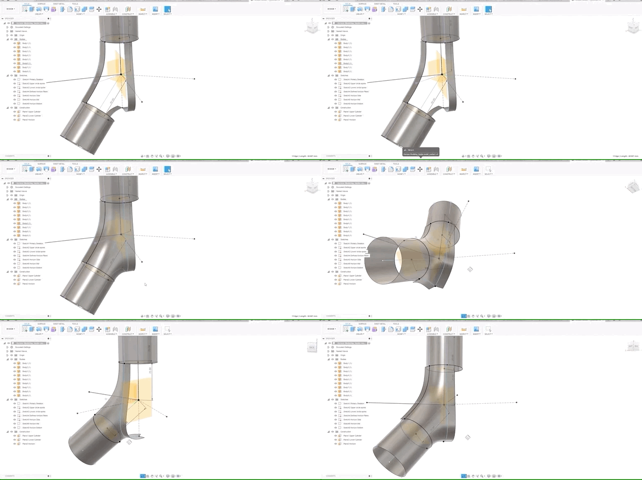
7. If the patch is looking good, we can go ahead and mirror this to the other side and pattern the surface to the trio.
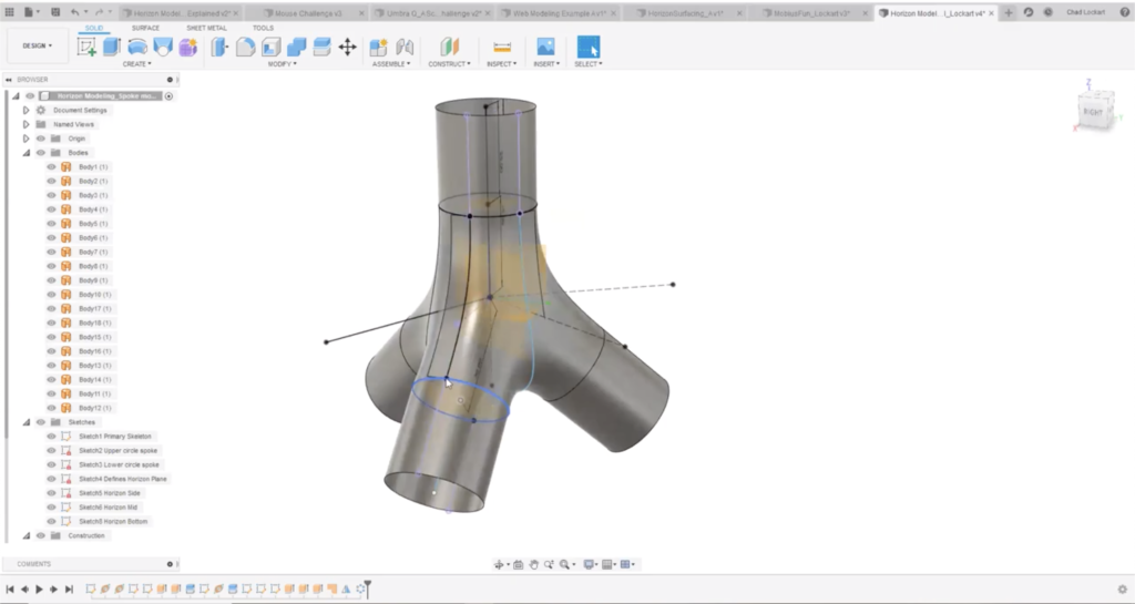
8. For the final step, turn the sketches back on and start playing with them. At this stage, you can modify the sketches, grab the ones that aren’t fully constrained, tweak the downward angle of your spokes, and change the way the profile transitions by playing with the tangent arcs on the splines.
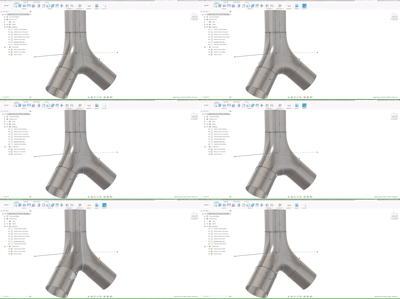
Congratulations, you have just created a class A geometry in Fusion 360, and it’s feature-based, and it’s parametric! We hope you find these exercises useful and that you now feel empowered to produce class A geometries using Fusion 360.
Not using Fusion 360 yet? Download today and create your next class A geometry like a pro.