Learn the difference between standard and configured designs, see how configurations are defined, and learn the basics of configuration workflows in Autodesk Fusion.
Configurations in Autodesk Fusion enable you to make data-driven decisions, helping you reduce prototyping and manufacturing time while accelerating time-to-market. Read on to learn the difference between standard and configured designs, how configurations are defined, and gain a foundational understanding of the overall configuration workflow in Autodesk Fusion.
Configurations overview
Standard design vs. configured design
A standard design is a single design where you can create components, sketches, and bodies to form a mechanical assembly. On the other hand, a configured design is a design document that contains two or more configurations that you define in a configuration table.
As with a standard design, you can use configurations in downstream workflows and other design documents. You can create a configuration from scratch or by converting a standard design to a configured design.
With a standard design, when you create design geometry you define aspects of the design. In the example below, the design’s defined aspects are the dimensions of the box.
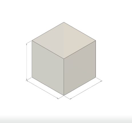
However, with a configured design, you can configure aspects of objects and features in the design to create configurations. A configuration is a single variant with a configured design.
For example, if you configure the length, width, and height parameters of the box below, you can create different size variations that all share a single source of truth. Essentially, configurations let you create a group of related designs, in one design document.
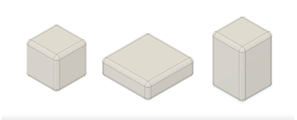
Configurable aspects
Autodesk Fusion gives you the ability to configure states and parameters for various aspects of objects and features. Let’s take a look at what aspects are configurable:
- User parameters – You can configure user parameters to drive key aspects of our design. These include criteria such as length, width, and height to create different sizes of a design.
- Feature parameters – You can configure feature parameters for most parametric features in the Fusion timeline such as sketch dimensions, extrude distance, hole diameter, pattern quality, and fillet radius.
- Suppression – Suppression can be configured for most parametric features in the timeline. You can also configure suppression for some objects from the browser like components and sketches. This will suppress the feature in the timeline that created the object.
- Visibility – You can configure visibility for most objects in the browser.
- Appearances – Appearances can be configured for the default component, internal components, external components, and bodies. An example is configuring different appearances for color of finish options.
- Physical materials – You can configure physical materials for default components, internal components, and bodies. This is useful when configuring physical materials to prototype or manufacture.
- Sheet metal rule – The sheet metal rule for each sheet metal component in an assembly can be configured. If you have a product that is folded, this gives you the ability to configure different materials and thickness options that are the best fit.
- Plastic rule – You can configure the plastic rule for each component with a plastic rule assigned to it in an assembly. For example, you can configure different plastic material options for an injection molding design, and use the design advice or tools in the simulation workspace to compare results to determine the best design.
- Properties – In the properties tab in the configuration table, you can configure the part number and description for each configuration.
- Configured components – A configured component is a configuration that is inserted into another design document. You can configure the insert feature of any configured component you’ve inserted into another design.
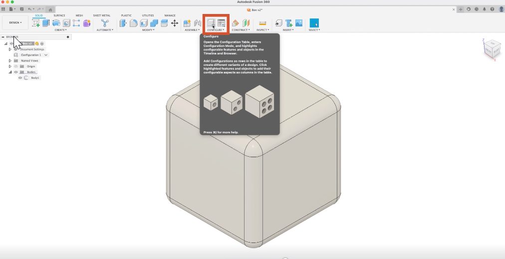
How to access configurations
To start, navigate to the configure panel and click configure. This will activate configuration mode and display the configuration dialog.
Within a configuration table, a configuration is represented as a row. To add configurations, enter the number of configurations you want to create and click add configurations.
When configuring aspects of your design, when configuration mode is active, configurable objects in the browser and configurable features in the timeline are highlighted. By clicking an object or feature, a list of configurable aspects display.
The list of configurable aspects depends on the object or feature type. If you check an aspect to configure it, it will display in the table as a column. Checking more aspects will also add them to the table.
Configuration table
In the configuration table, you have the ability to add, activate, rename, edit, delete, and sort configurations and configured aspects.
Once you’ve added configurations and configured a few aspects of your design, you can edit the values or toggle the states in each column for each row to specify the differences between configurations. You can then activate different configurations to validate the changes you made.
Theme tables
As you configure your design, you can organize configured aspects in theme tables. A theme table is a child table where you can manage and organize columns. This allows you to create consistent variations across configurations.
When you configure an appearance, physical material, plastic rule, or sheet metal rule, a theme table automatically generates. You can also create custom theme tables.
In each theme table, a theme is represented as a row. You can edit each column in each theme to define the differences between them.
In the example below, each theme table is represented as a column. Once you’ve customized the themes in the theme table, you can select a theme for each configuration.
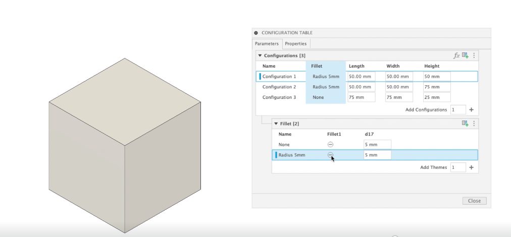
The appearance theme table organizes the different appearance options for objects in the design.
To create a custom theme table, select columns in the top table, right-click, and select move to a new theme table. This is a flexible way to group similar configured aspects and simplify the top table.
So you’ve created configurations – what’s next?
Once you’ve created the configurations of a design, you can use them in several workflows in other workspaces within the configured design and in other design documents.
In the design workspace, you can insert a configuration as a configured component or derive a configuration into any other design document. You can also create rendered images of each configuration.
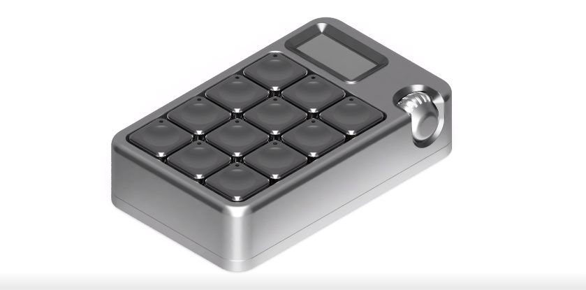
You can create, annotate, and document exploded views and animations for each configuration.
In the simulation workspace, you can create, solve, and copy simulation studies for each configuration, and compare results from different configurations.
You can create and solve generative design studies for each configuration and compare results from different configurations. Configurations carry through to the generative design environment to generate and compare different design options.
In the manufacture workspace, you can create setups and manufacturing models for each configuration.
And last but not least, you can also create drawings for each configuration.
Ready to explore configurations in Autodesk Fusion?