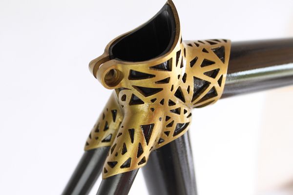
After coming back from the RAPID conference I kept thinking about building a custom bike by printing the lugs which hold the bike frame tubes together. The concept is not new. Here is one builder from Australia who has led the way in creating titanium lugged bikes and another artist, Ralf Holleis, who has 3D printed titanium to create a real beauty.
Photo: Ralf Hollies
I thought I would do some experimentation in Fusion and share the process. Maybe some new capabilities you would like to try out.
Tubes are held together with lugs
I started with an attached canvas that had the basic layout. In order to get the size of the canvas correct I selected the canvas in the browser and using the right mouse button to display the options. Calibrate will allow me to define two points that will scale the canvas properly. Then I created a sketch for the main tubes. The Model workspace has a Pipe command that allowed me to create the basic tubes. I created one set for the tubes and another set which was one millimeter larger for the lugs. I combined these lug pieces together with Combine and filleted the intersection. That was the base solid lug I would use to experiment with. I created several copies so I could try different approaches.
Chopping it up
I wanted to create some recesses in the lugs where I could feature some patterned designs. This could be approached by projecting sketch curves from a view but I wanted a result where the recess walls were dynamic. I used T-Spline bodys as 3D cutting surfaces. The lug body was in one component and the T-Spline bodies were in another. I applied appearance colors to each component to easily distinguish where the cut lines would be as I modeled the T-Spline with Edit Form.
The T-Spline Thicken command has an option for “No Edge” that will allow you to offset these cutting surfaces which can be useful to keep a nice distance between the cut lines. Once I was satisfied with results I used these bodies in the Model workspace with the Split Body command to create the cuts in the lug body. The interior portion was then offset inward with the use of the Press Pull command.
Twisted
To create a raised pattern on the recessed area I needed to create some 3D curves that would wrap around the cylindrical interier. In the Sketch workspace there is a “Project to Surface” capability that will project a curve or T-Spline edge down to a face. I created a T-Spline cylinder that was concentric with a solid cylinder. Notice in the video that I use the Reorient option when in Edit Form to make sure I am twisting the end of the T-Spline cylinder concentric to the underlying cylinder.
Piping the twisted curves
Now I needed to create some pipes on those twisted curves. This would provide the pattern for the interior. I used the T-Spline Pipe command with a diameter of 1.25 mm which would place those pipe centers midpoint in the recessed faces of the lug. I tried it with all the twisted curves at first but didn’t really like the blended intersections so I did the twists from one direction and then the other. The pipes were then converted to solids and combined together. I did run into some problems with the intersections at the ends so trimmed several prior to joining which solved the issue.
Print ready
These were some experiments to exersize Fusion capabilities but the results created a valid solid model that converted for 3D printing. Titanium printing is pretty expensive so I don’t think I am ready to invest yet but maybe with a few more itterations I will be ready.


