This post is also available in: Français (French) Italiano (Italian) Deutsch (German) 日本語 (Japanese)
Deburring in Autodesk Fusion eliminates labor-intensive manual deburring tasks, saving you time, money, and a lot of frustration.
What is deburring?
Deburring is the process of removing small material imperfections on the edges of parts and components that have been CNC machined. These material imperfections are called burrs. Ultimately, a part can only be considered ready to ship after finishing the deburring process.
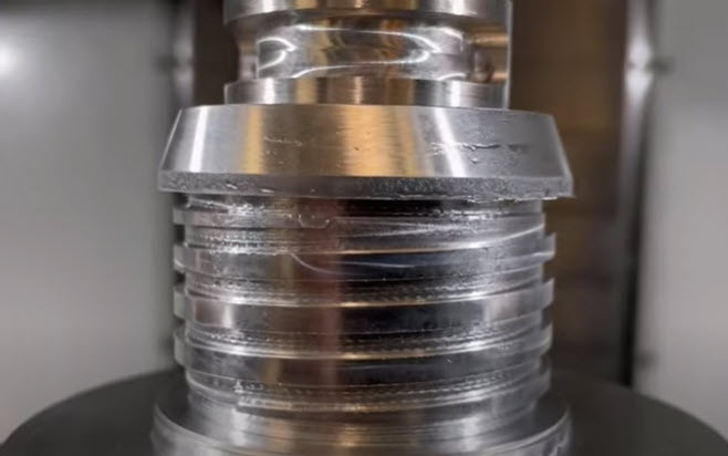
What causes burrs?
Burring is extremely common during the machining process. Burrs can occur during several different stages of CNC machining, including stamping, molding, turning, milling, drilling, plasma, water jet, laser cutting, and more.
When burrs form, they may take one of three main types:
- Rollover burrs: Rollover burrs are the most common. They look like tiny bits of curled metal projecting from the part.
- Poisson burrs: Poisson burrs occur when too much metal collects at the end of the part and extends sideways.
- Breakout burrs: Breakout burrs swell upwards and appear as though they are breaking out of the part.
How to access deburring in Autodesk Fusion
Deburr is available as part of the Fusion Machining Extension. The deburr toolpath in Fusion aims to address burrs by automatically detecting external sharp edges and removing them across the entire part.
This toolpath gouges the surface by a user-defined amount to remove the burrs. It’s used on areas where you have a corner between two surfaces that change direction from one another. It runs the tool along the edge so that the sharp burrs are removed. As a result, the manual processing of deburring is significantly reduced.
The deburr toolpath is 3, 4-and 5-axis capable, helping to eliminate labor-intensive manual deburring tasks. Ultimately saving you time, money, and a lot of frustration.
Deburring in Autodesk Fusion
To start, you can access deburr in the manufacturing workspace from the 3D drop-down menu with the Machining Extension enabled.
Prior to creating your first deburr toolpath, it’s important to understand what tool geometries Fusion supports bill noses, lollipop tools, chamber tools, sport drills, flat-end mills, and tapered tools are all supported. Some tools do require additional considerations that include:
- Spot drills are supported in 3, 4, and 5-axis; however, you’ll need to enable the “cut at a fixed point on the tool” option in the multi-axis tab in order to use them.
- When deburring with an endmill, the side portion of the tool is used for deburring edges. As a result, you’ll need to again, like spot drills, check “cut at fixed point on the tool” in order to use end mills for deburring your parts.
Next, you’ll need to define how the toolpath identifies edges in the geometry tab. “Automatic” interrogates the entire model’s geometry and attempts to machine all of the external edges.
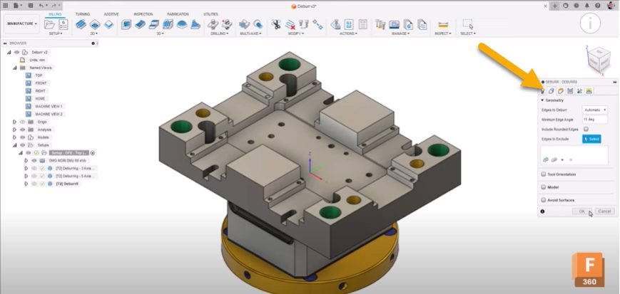
Specifying a “selection” will limit the toolpath to only the user-defined edges specified. There are additional options that allow you to exclude additional edges that are too close to fixturing or clamps.
Pro Tip: After navigating away from the geometry tab, right-clicking the toolpath within the browser allows you to quick-select further selections or edges to exclude depending on whether you have “selection” or “automatic” enabled.
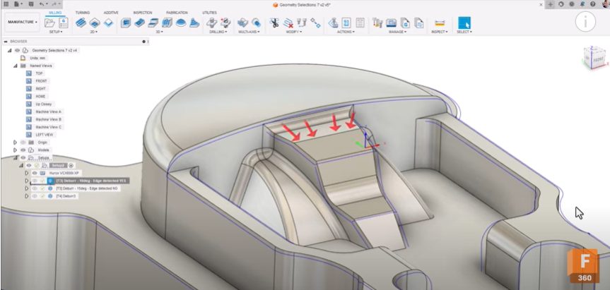
Minimum edge angle
A minimum edge angle is generally used to automatically filter out any significantly obtuse edges from detection. This acts the same as the bi-tangency angle in the pencil toolpath and the threshold angle within steep and shallow. An edge with an angle less than the user-defined value will be ignored.
In the example below, the edge has a draft angle of 12 degrees from the horizontal face to the edge it’s connected to. To stop the edge from being detected and subsequently deburred, adjust the minimum edge angle to more than the draft angle of the edges being deburred. In general, the more obtuse an edge is (closer to 180 degrees), the less of a burr it is.
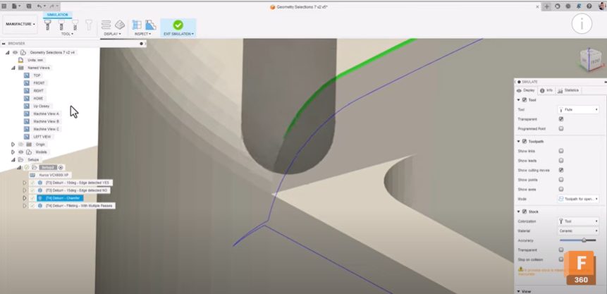
Passing tab
In the passing tab, you can deburr edges in one of two ways:
- Chamfering: When using the chamfering option, the tool runs along the edge to produce a chamfered edge.
- Filleting: should be used with multiple passes and runs the tool so that the final edge appears filleted.
The edge shape defines how much material will be removed from the edge during the deburring process. With “constant width,” the width of the chamfer will always be the same for each edge. However, the depth of cut may vary depending on the geometry being machined in order to maintain that constant width.
With “constant depth”, the depth of the chamfer being created will remain the same for each edge. However, the width of the chamfer may change depending on the geometry being machined to maintain the constant depth.
Deburring corners between edges
The deburr toolpath is also suitable for deburring corners between edges. Some corners have a requirement to be deburred. However, due to the nature of the geometry, the corners aren’t accessible. By enabling the “cut with tip of tool,” the deburr tool attempts to cut more of the corner by using more of the tip of the tool.
If you’re running an older generation controller, which can lead to jittery and stuttering machine motion, you can make the machine motion smoother by checking the “add loops for smooth motion” box. This offers smoother motion control when the tool transitions between edges by way of circular loops.
Multi-axis tab
Last, there is the multi-axis tab. In some instances, you may need to invoke multi-axis capabilities in order to provide the tool with more accessibility to deburr as much of the part as possible.
Selecting 3-axis will only machine edges that it can physically reach. 4-axis is suitable when you have a rotary style part that needs to be deburred using the addition of an A or B-axis.
In 4-axis mode, the primary method of tilting can be defined as either “to rotary axis” or “zero lead angle.” “To rotary axis” means that the tool tip will always point to the defined rotary axis. Applying a further tilt angle will tilt the tool towards the rotary axis.
Zero lead angle aligns the tool with the average angle of the two edges being machined. Applying a further tilt on top of the zero lead angle will then additionally tilt the tool towards the rotary axis.
5-axis mode
Primary mode, as in the 4-axis variation, describes the movements of the tool as and when multi-axis motion occurs. Using a lead angle may be appropriate for situations where you want a small lead angle to get a better surface finish by cutting with the leading edge of the tool. “Tilt to Z-axis” will tilt the tool to a preferred angle and auto-adjust that angle when a collision is detected. When a collision is no longer detected, the tool will revert back to the preferred angle.
Pro Tip: Setting the preferred tool axis to “0” will maintain a vertical tool axis (or 3-axis) toolpath while only tilting the tool to avoid collisions when the toolpath detects a state of collision.
Machine motion smoothness
In order to maximize machine motion smoothness with the deburr toolpath, it’s recommended to set the high feed rate mode within the linking tab to “always use high feed.” This will typically make linking moves smoother and will mean your machine axis will remain synchronized as it traverses to its next orientation.
To learn how to master deburring in Autodesk Fusion, check out the following video tutorial.
Get started with deburring in Autodesk Fusion
Take the manual process of deburring out of your current workflows. See how Autodesk Fusion can help.