
V 2.0.9512
We fixed an issue where some of you were experiencing instability in the software when you tried to view 3D PCB in Fusion Electronics. Now it should work more smoothly.
Some of you also told us about an issue where the content manager was showing a blank field after you tried to import a package from the web into the device editor or Add Local Package after an import. This is now fixed and the field will appropriately reflect what has been added.
If you’re running Fusion 360 in German and need to run Electronics Cooling studies, we’re glad to report that we have resolved a pesky crash issue that was preventing you from running them. Now it works just fine.
We squashed a bug found in the Export Flat Pattern command where exporting a sheet metal flat pattern as a DXF inexplicably left out the TEXT layer.
Some of you working in the Additive tab of the Manufacture workspace were experiencing crashes when you tried to open a FFF setup, generate toolpath, went over to Simulation, and closed Fusion 360. This is now fixed.
V.2.0.9442
We fixed an issue where many of you were not able to start Fusion 360 or experienced crashes on machines running macOS with Retina Display. We discovered that this was related to a case-sensitivity issue and have fixed the issue. Fusion 360 should launch without a hitch now.
V.2.0.9440
We heard that some of you working in Fusion 360 with your language setting set to German have been experiencing issues saving your designs. Apparently clicking on the OK button in the save dialog did nothing. Sorry about that, someone tripped and accidentally unplugged a wire – we got this sorted out and now you should save just fine.
V.2.0.9439
Usability
Heads up: we will be ending our support for macOS 10.13 in April 2021. If you are still on 10.13, plan accordingly to upgrade to the latest macOS so you can continue to use Fusion 360 after April 2021.
Notable fixes
- jddubbs told us about a problem where Fusion 360 would hang every time he tried to open a document that contained certain inserted x-refs. We were able to give him a work-around while we investigated deeper, and we’re happy to report that we’ve also fixed this issue.
- kthrendyle shared a screenshot with us where measurements generated from the measure command from a face to a hole annoyingly overlapped one and another, making it really difficult to see the values. We tweaked how the values are displayed so that they no longer overlap each other anymore.
- guenther.andresen posted a great animated gif of an issue he found regarding selection filters and how window selecting a model with the edge selection turned on didn’t actually select the edges at all. We discovered that this was not working on non-English UI. Sorry about that; this is now fixed.
Sketching & Modeling
Improved! Chamfer tool
Design workspace > Solid Tab > Modify > Chamfer
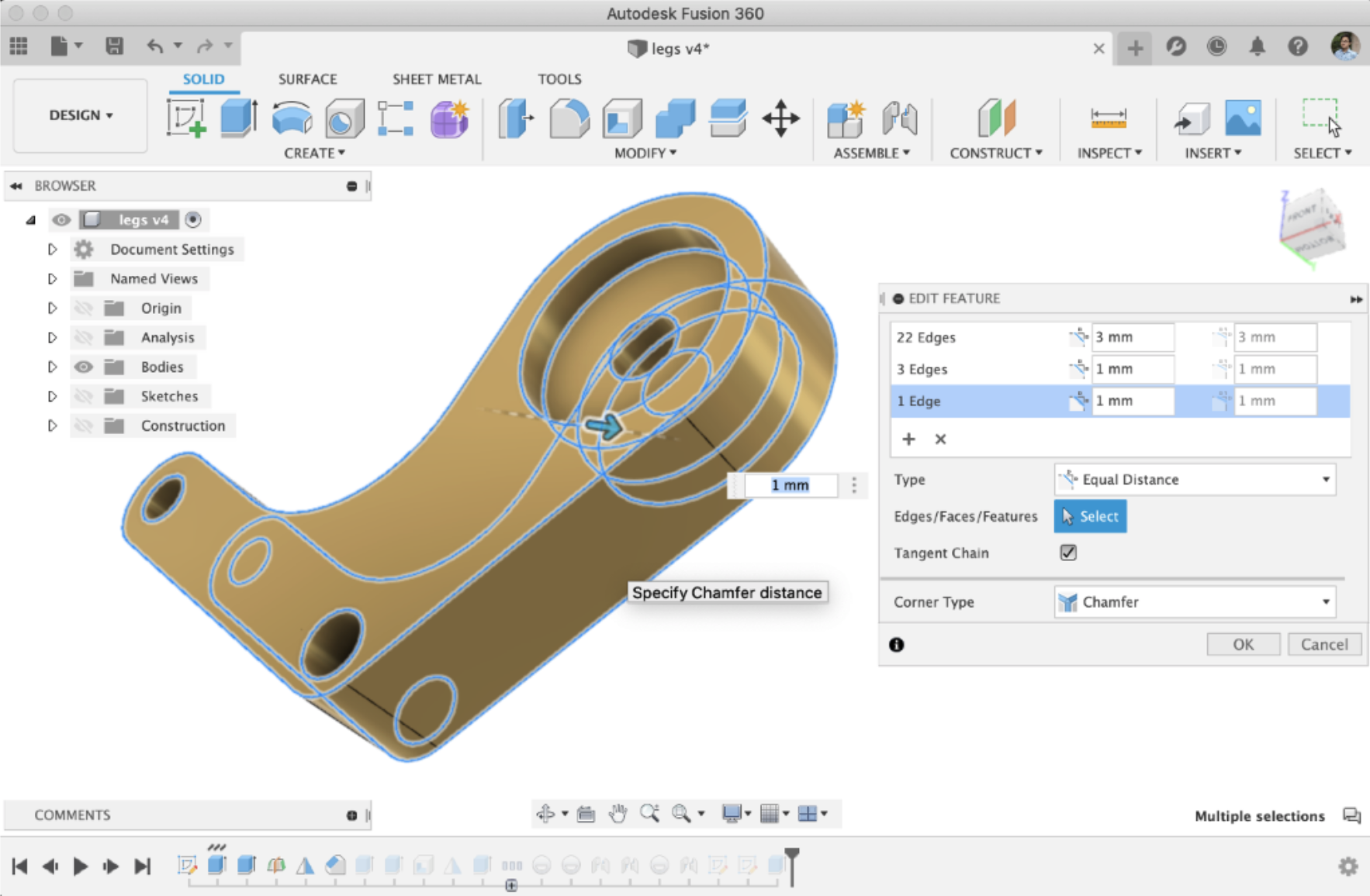
We’ve improved the Chamfer command by enabling you to select multiple groups of edges and with different Chamfer distances and angles for each group. You can also select faces too, and the command will chamfer the edges around the face, just like how the Fillet tool behaves.

At the bottom of the command dialog, you also have the option to pick the Corner Type, such as corner blend chamfer or 3 edge chamfer. We’ve also finally fixed an issue that has been lingering with Chamfer for a while. You can now flip a 2 distance or distance angle chamfer.
See help documentation for Chamfer.
[expand title=”See notable fixes”]
- HughesTooling reported a bug in Pattern-on-path he found while trying to help another user. It failed to compute when he was trying to move a component into another component by dragging the sketch, which was used to make an Extrude Cut and then patterned. This is now fixed.
- HughesTooling also found a bug in the thread command where using the 10-32 UNF Designation and setting the Class as 2A caused the thread to fail. Sorry about that – we got this sorted out.
- We heard reports of an issue where, in the Mirror command, selecting multiple faces with the Face Selection filter and a construction plane caused Fusion 360 to freeze. We looked under the hood and found the bug that was causing this, so we crushed it and now it works as expected.
[/expand]
Electronics
New! Schematic Editor
New File > Electronic Design > 2D Schematic > Command line > “explib”

There are times that a design has been provided to you, but not all the libraries are available, or you wish to reconcile all the components of a design in one library. The Fusion 360 schematic design file has all the properties of the component on the schematic; therefore, library dependency is not necessary. With this new feature you can extract all the components into their original library or into one library. Making it easy to re-use in different designs, or make changes to apply to the current design.
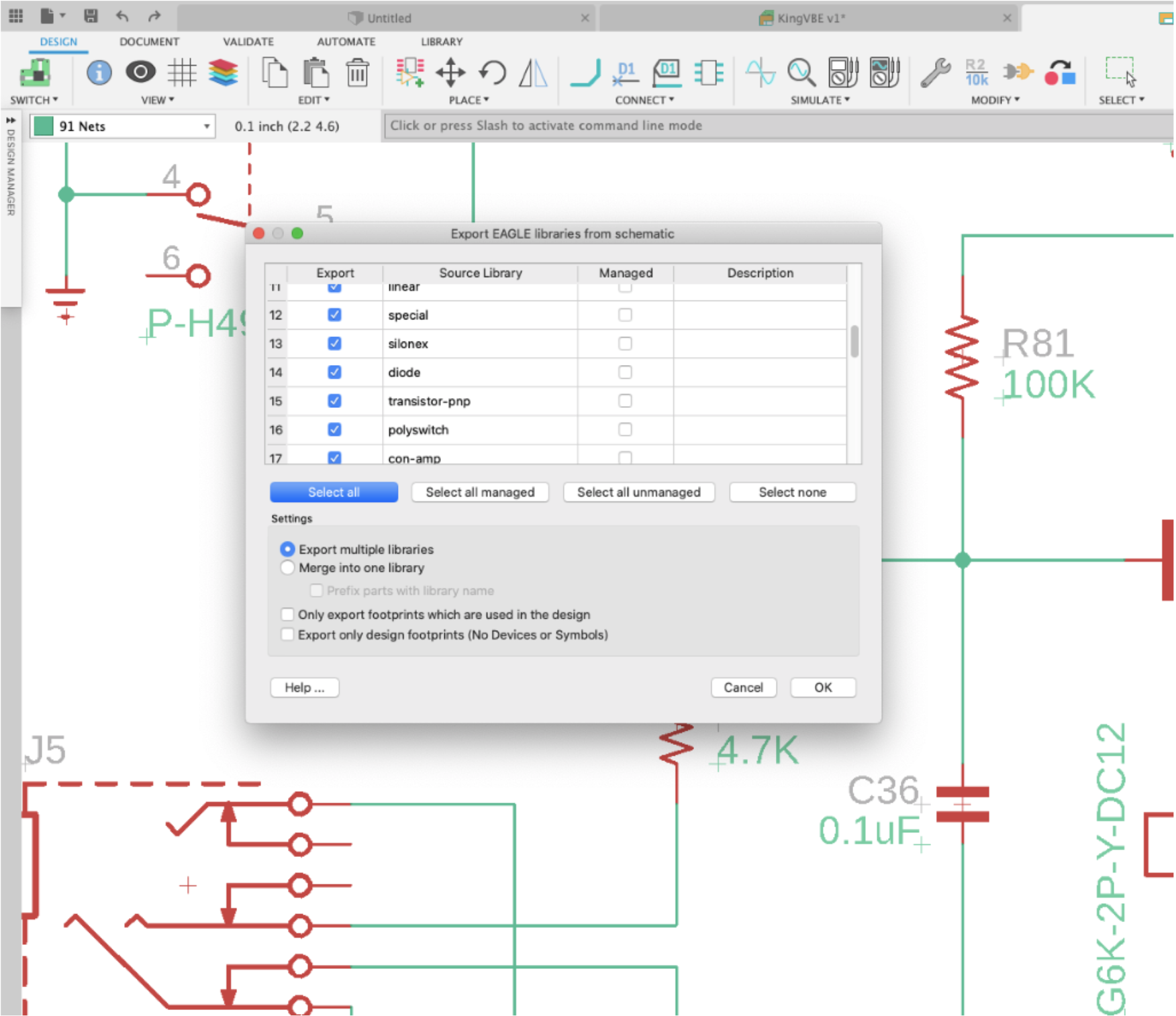
New! Assign 3D models to footprints that do not have pads
New Electronic Library > Package Editor
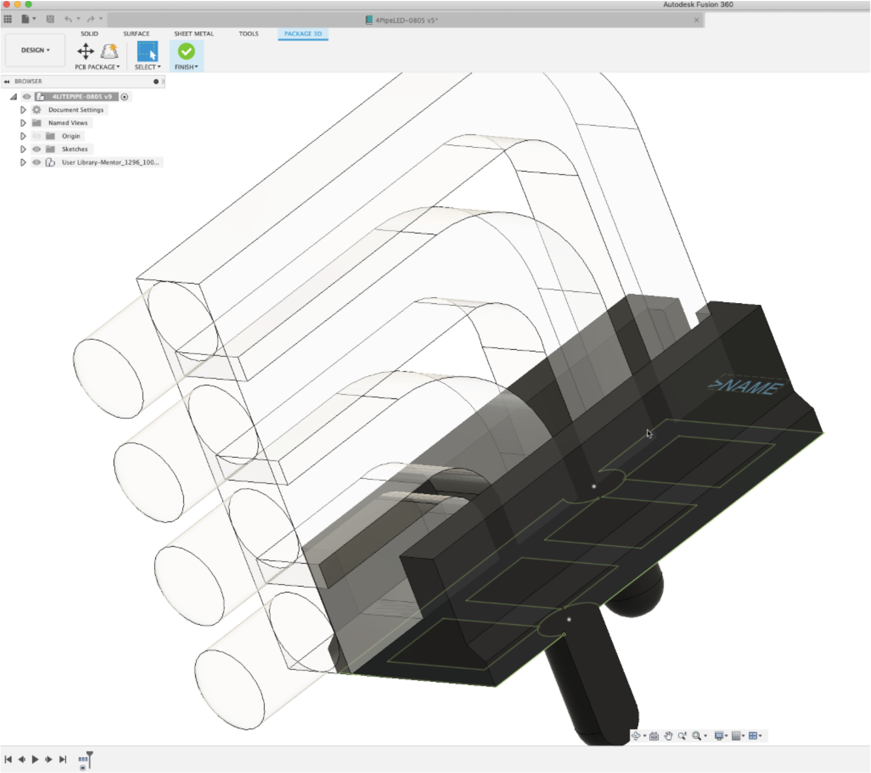
Previously, you were unable to assign 3D models to a 3D package footprints if the model did not have pads. We’ve added the capability to now include 3D geometry (such as the light pipes in the example below) as mechanical objects as part of the 3D package design, even if it doesn’t have an electronic representation in the schematic.
New! New libraries and new parts
File > New Electronics Design > New Schematic > Add part

In this release, we have added three new libraries- Audio-devices, Fuse & IC_RF-Wireless. These libraries contain popular parts like Microphones, PTC fuses & RF Transceivers.

Along with that, we also added popular parts like Trim-pots, Tactile Switches, Power relays, Sensors & few connector types to existing libraries such as Resistor, Switch, Relay, Sensor, Connector respectively.
Improved! Create custom footprint for surface-mount packages
New Electronic Library > Create tab > Package Editor > PCB Package drop-down > Package Generator > Custom Footprint checkbox
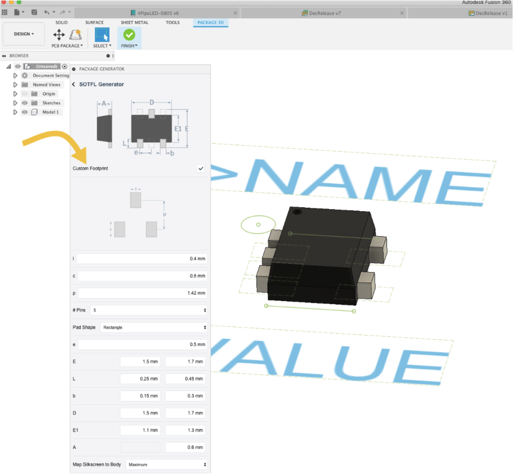
You now have the option to create custom (Non-IPC ) footprints for your surface mount packages. Within the Package Generator dialog, you’ll see a Custom Footprint check box option. When checked, the dialog will display more fields for you to customize pad sizes without altering 3D model dimensions.
Improved! Better guidance and error messages
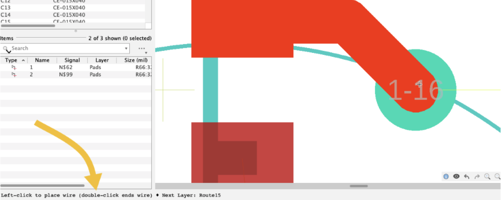
For EAGLE users transitioning to Fusion 360, we’ve updated the UI to include command guidance at the bottom of the window. According to the current active command, the command guidance prompt will alert you of the possible actions that can be performed.
We’ve also made some error and info messages that typically appeared in the bottom right corner of the screen transient so that they no longer require you to close them. They will appear and fade out automatically.
Improved! Insert special characters for true type font text
New Electronic Design > PCB Board
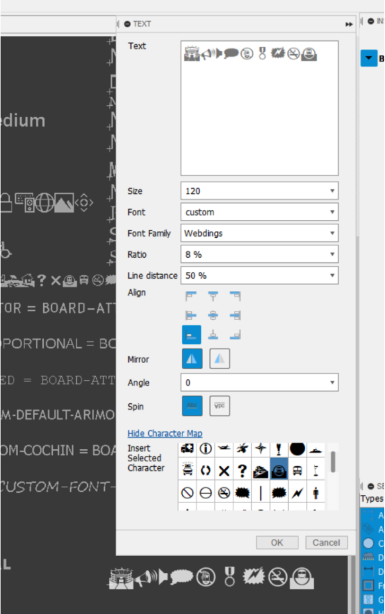
When entering text, you are now also able to select and insert any of the currently selected True Type Font (including Proportional and Fixed fonts) available characters, as well as those that are not available directly using the keyboard.
Improved! Default units now available in Preferences
Preferences > Default Units > Electronics
Now in your preferences, you can set/change the default units for new schematic documents as well as new board documents that you create.
[expand title=”See notable fixes“]
- rj.duran reported an issue where he got a series of errors saying that his Eagle library files failed to open after he closed and reopened his laptop with Fusion 360 running during this time. Sorry about that – we dug into this issue and found some wonkiness in the code. This is now fixed.
- Jeff_Birt told us about an issue where the 3D PCB board did not appear successfully when he tried to open it. Instead, there were profiles missing and he was unable to select the missing profiles either. We worked him and came up with a work-around as we got working on fix. Now the fix is in.
[/expand]
Drawings
New! Welding Symbols
Drawings workspace > Symbols > Welding
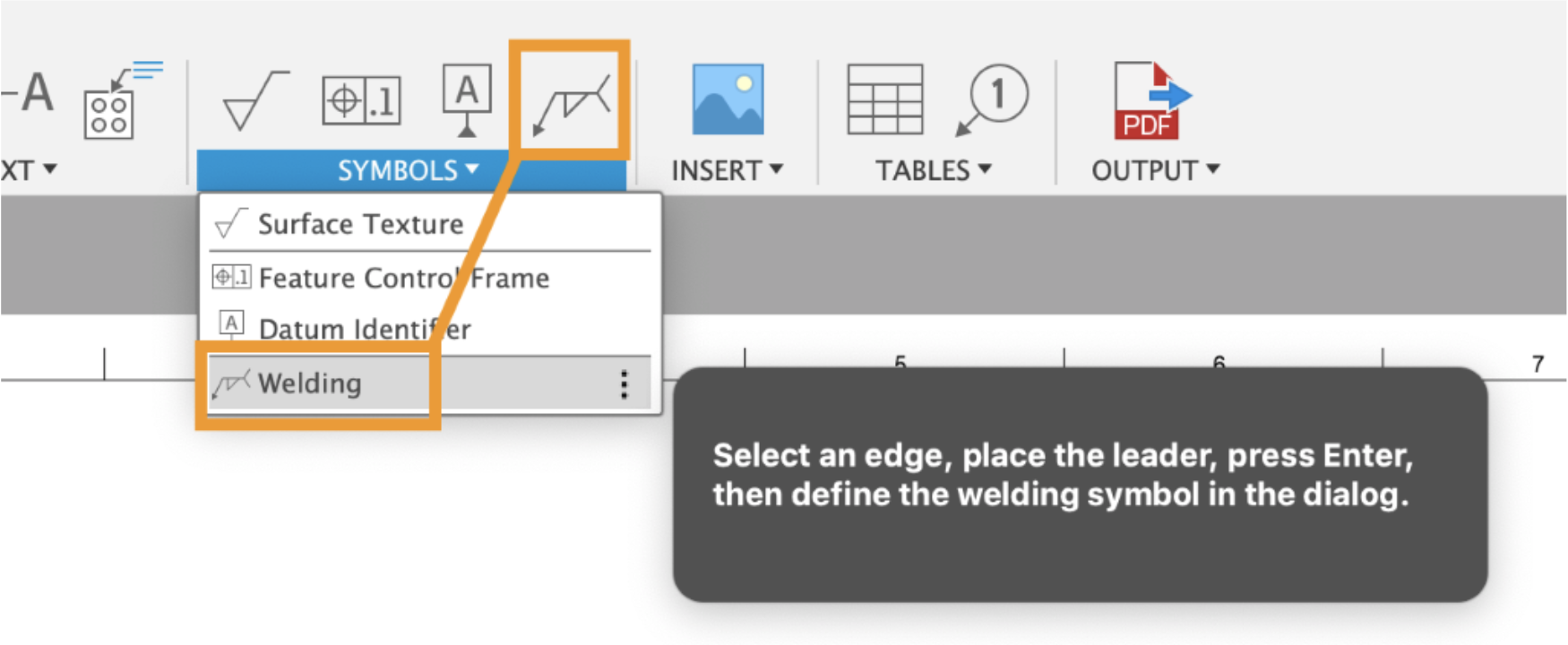
Ah, Welding Symbols. They are necessary to have if you want to convey any kind of welding information on your drawings. So many of you have asked for this, and we’re glad to say that it is now available as a dedicated command within the drawings workspace.
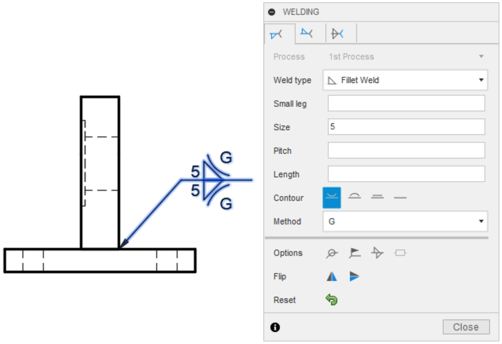
You can start by selecting between the Arrow Side, Other Side, or Tail Note tab. Within the tab, you have options for Weld type, and then additional options based on the weld type. Here you can see, for a Fillet Weld, you can set the dimensions of the weld, including its pitch and length, and finishing contour. At the bottom (below that bar) are options that affect the entire weld. These weld symbols conform to ISO and AWS standards, and there are some differences in weld types and options between those two standards.
New! Copy, Paste Table
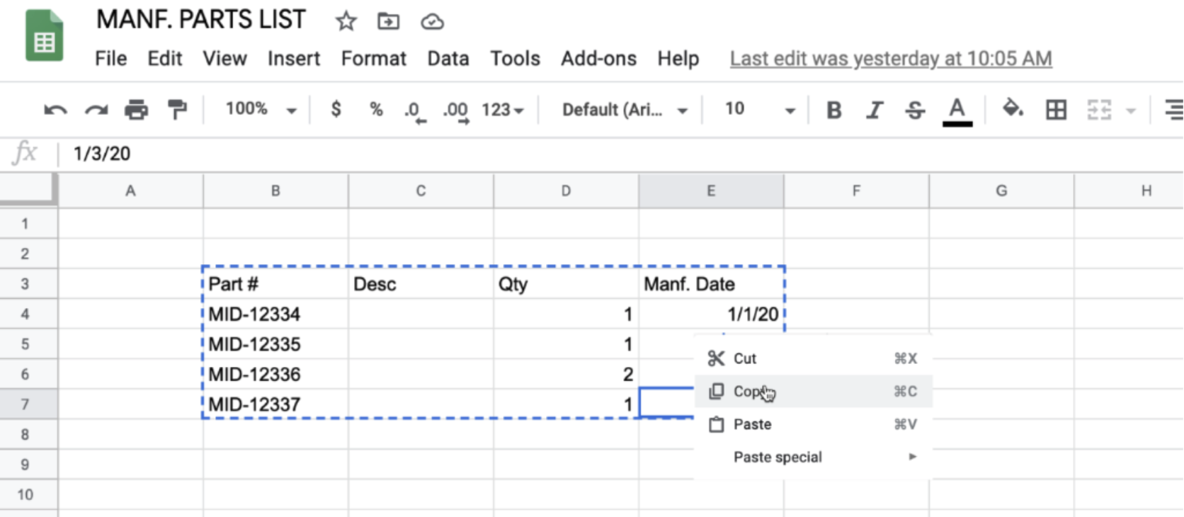
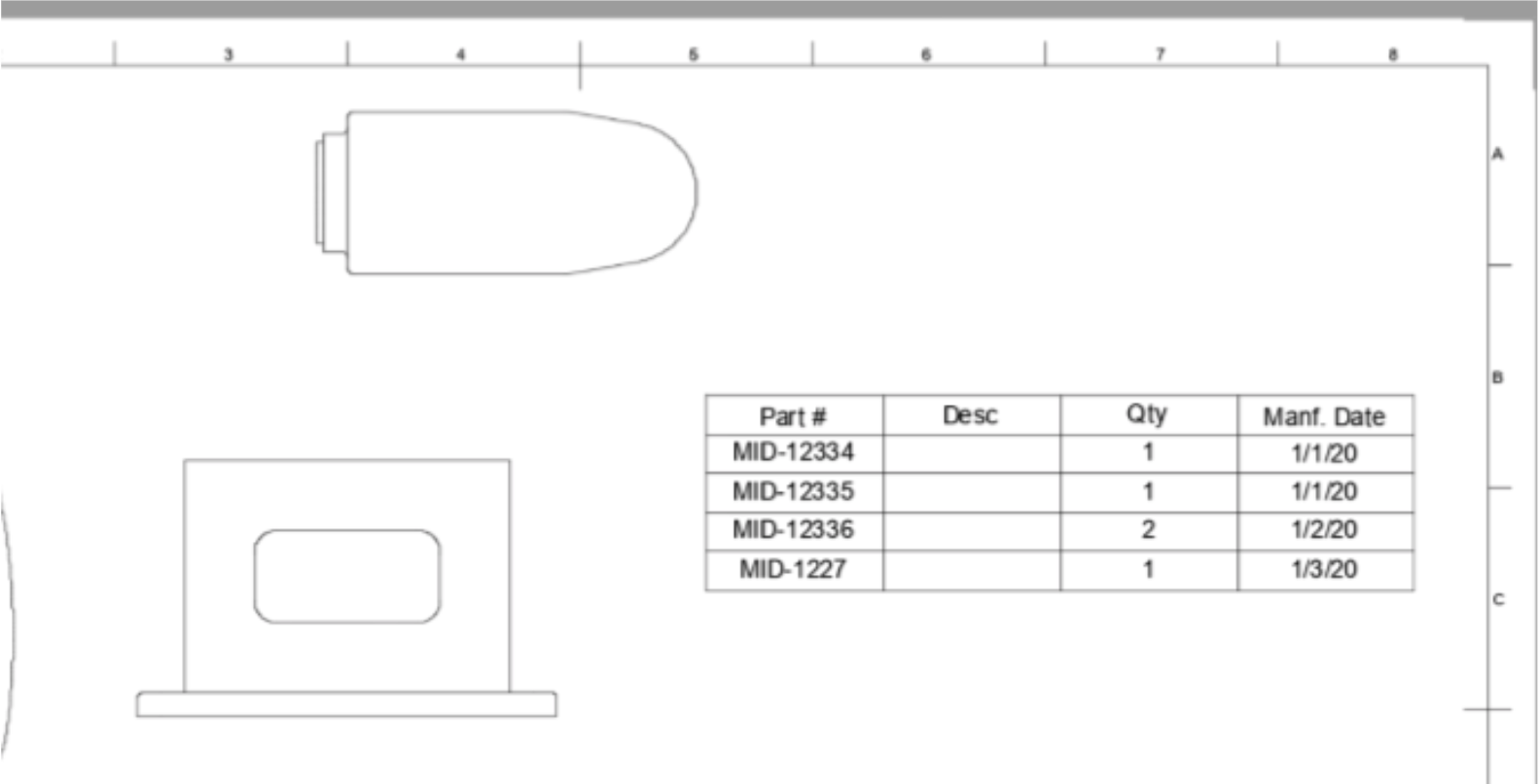
Good news! If you’re using spreadsheets for organizing your cutting list data, purchasing list data, or any tabular data, you can now copy a set of cells from your spreadsheet and paste them directly into your drawing as a table with all the contents.
Bonus: this also means that if you’re using Bommer with Fusion 360, you can copy and paste all that good data that Bommer exports right into your drawing as well, which can save you a bunch of extra typing. Check out their blog post to learn more.
[expand title=”See notable fixes“]
- Whenever MariusBaard tried to scale his drawing of a derived part, Fusion 360 got really confused and froze. We cleared up the confusion and now the scaling should work fine.
- By updating our drawings engine, we fixed a crash issue that sometimes occurred when you tried to toggle “suppress” on some components in your browser.
- We also improved the stability and performance of drawings created with the ASME standard.
- We’ve made significant improvements to parts lists and balloons over the last few releases – looks like one issue got past us. No longer, your balloons should stay where placed.
- We were incorrectly applying the wrong precision value to angular dimensions in our new Hole & Thread notes; this has been fixed, your angle values now show the right number of digits to the right of the decimal.
[/expand]
Generative Design
New! Remote Forces and Constraints in Experimental Solver and Features Preview
Generative Design workspace > Design Conditions > Structural Loads or Structural Constraints
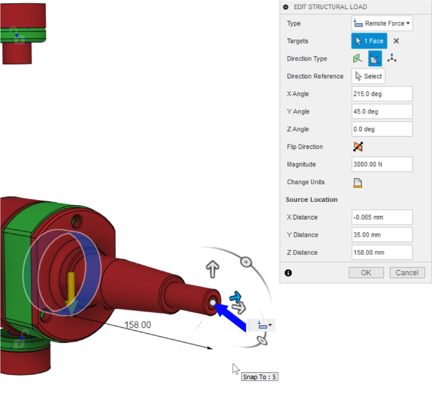
Many of you have told us that applying loads and constraints directly to the design space geometry was often challenging, as they typically did not know the loads at those locations, or they could not accurately create the type of load or constraint scenario that best represented their requirements.
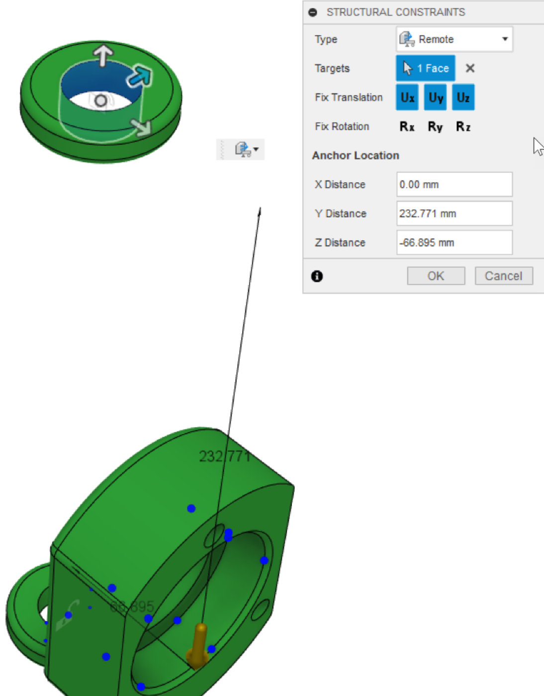
In this update, we have added remote forces and remote constraints to the Experimental Solver and Features Preview. To enable remote forces and constraints, you must opt into the Experimental Solver and Features preview. Once the preview is enabled, remote forces and remote constraints will be found in the Structural Loads and Structural Constraints commands, respectively.
See help documentation for Remote Force.
See help documentation for Remote Constraint.
Improved! Additive Manufacturing Constraints in Experimental Solver and Features Preview
Preferences > Preview Features > Generative Design > Experimental Generative Solvers and Features
In the September update, we released the ability to control the print direction for the additive outcomes created in each study. We also released our Experimental Solver and Features preview and talked about how this would be the future vehicle for delivering new solver functionality and robustness.
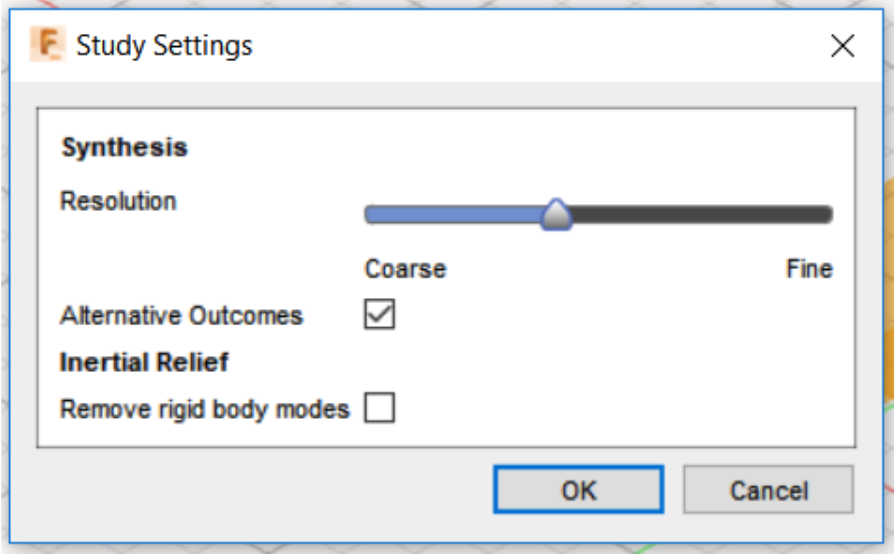
In this update, we have included a new additive constraint algorithm via the Experimental Solver and Features preview. To enable the generation of outcomes by this new algorithm, you must opt into the Experimental Solver and Features preview. Once the preview is enabled, the Study Settings dialog shows a new checkbox for Alternative Outcomes. Enable Alternative Outcomes on a study before generating to turn on the experimental additive solver.

When Alternative Outcomes is enabled, now you’ll see additional additive manufacturing outcomes that do a better job of meeting the overhang angle and minimum thickness definition, balancing design mass with support material required. Further, it was common to see outcomes with pronounced stair-stepping and other artifacts. We aren’t a fan of those either, and we’re happy to report that they should go away in the preview additive designs.
See help documentation for Experimental Generative Solvers and Features.
Improved! Favorites Properties
Preferences > Preview Features > Generative Design > Explore
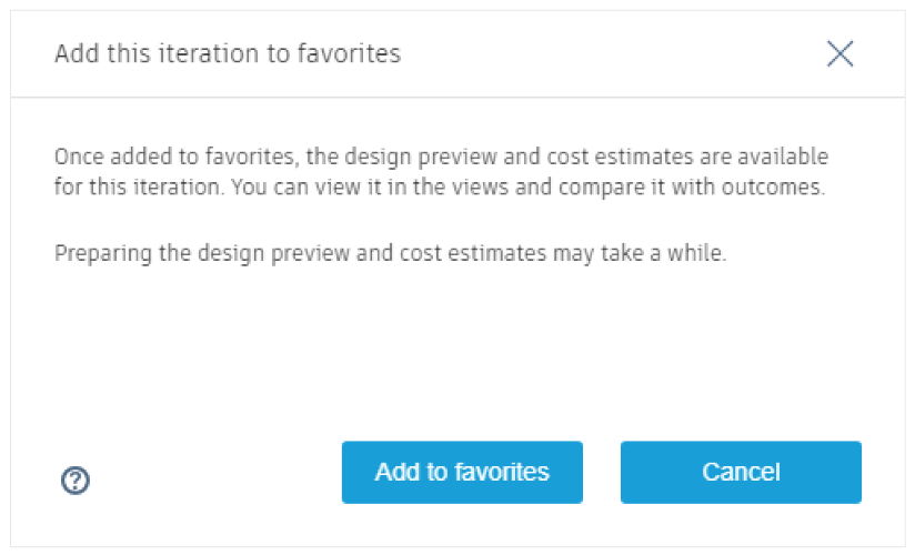
Now when you create a Favorite for one of the intermediate outcome iterations, the properties will be extended to include all the same information that a final iteration has, i.e. a design preview, cost estimates and visual similarity grouping will now be available. It will also be added to all of the Display views and can be compared with other final iterations. To mark an iteration as a favorite, click on the star icon located in the new Tag section in the toolbar and confirm in the dialog.
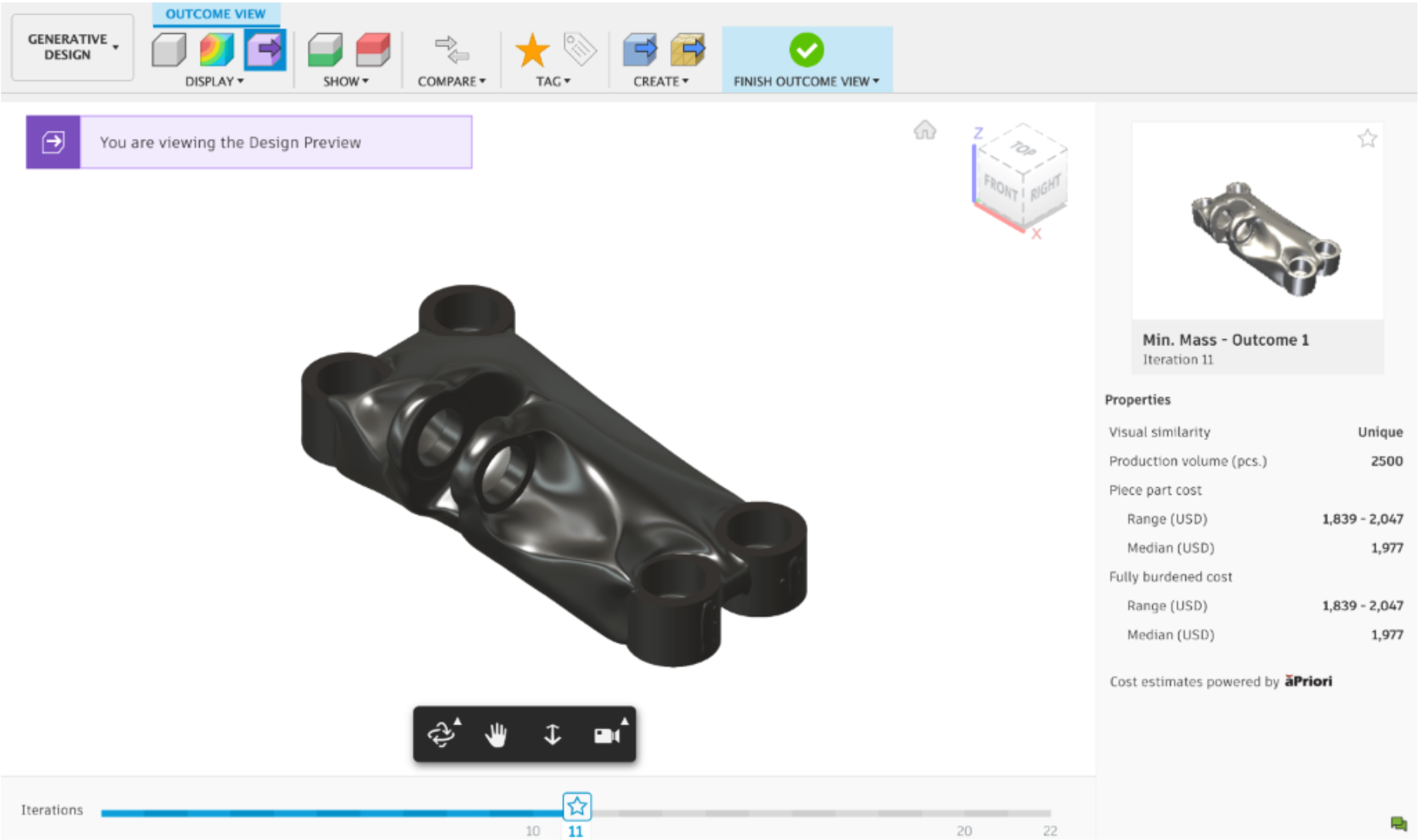
See help documentation for Favorites.
Improved! Costing Workflow
Generative Design workspace > Design Criteria > Manufacturing
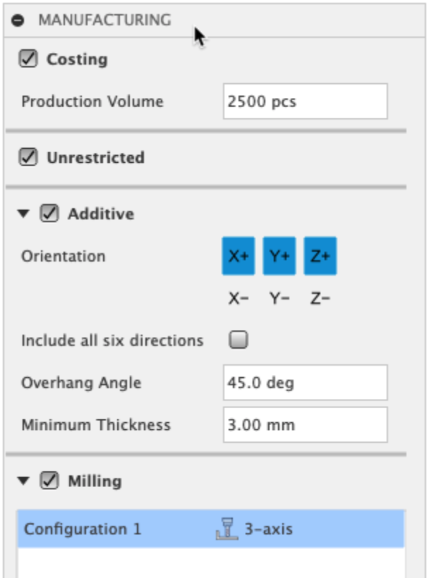
You can now explicitly ask for costing information to be generated with your generative studies. Instead of cost data always being calculated you can now control which studies you want cost information to be calculated for by enabling the Costing checkbox in the Manufacturing settings dialog box. This will provide you with additional control, useful for instance when you might be using custom materials for which costing is not available, or if you are exploring the design space without a need for costing information at the time of your studies. This checkbox will be “off” by default, so please make sure you enable it when looking for cost information as part of your generative studies.
See help documentation for Cost Estimation.
Simulation
Improved! Simulation Solver
The solver for electronics cooling has received some precision and speed improvements for this release. Running a simulation, the overall results will be very similar to previous releases, but they are technically more accurate and run faster.
Improved! More control over fidelity accuracy
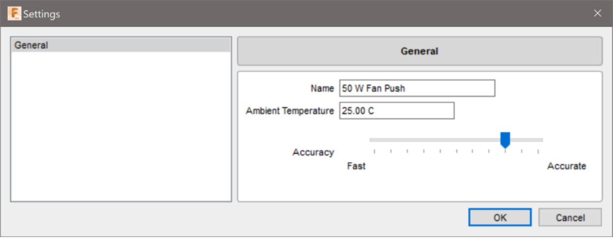
We also updated the dialog in electronics cooling where one can set the fidelity of the solve (optional) has also been modified to allow more repeatable replication between analyses. Previously, exact reproduction of the fidelity setting was difficult to attain. Now there are detents in the slider which allow for quick reproduction of identical fidelity settings.
Improved! Automation for fan assemblies
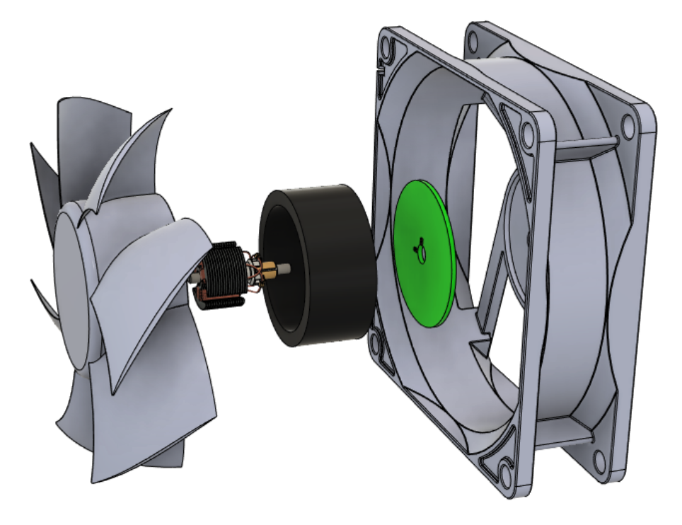
The automated fan idealization works the same for how it applies the air velocity. The change is in how we automate the material assignment for the housing of the idealized fan. In this release, the automation inspects the materials of all the parts and assigns to the simplified housing the material which occupies the most volume for the fan assembly. This is a more accurate representation of the thermal conductivity the solver sees for the thermal simulation. Overall, the thermal results difference will be minor, but be more accurate in the solids attached to the fan.
Manufacture
New! Arrange is now out of Preview

With the Arrange tool, you can create on-the-spot arrangements of objects on planes, sketches, or planar faces. Arrange has been available as a Preview since August and we are now graduating it, making it fully available in the Manufacture workspace. To use it, Create then Edit a Manufacturing Model, then click Solid > Modify > Arrange.
Arrange can still be accessed in the Design workspace too. To enable it in the Design workspace, go to Preferences > General > Design and select “Enable Arrange and Simplify tools”. Once applied, you’ll see the Arrange and Simplify tools under Design > Solid > Modify.
* Note that the Arrange tool is only available in Student, Start-up, and paid subscriptions.
Improved! Grooving Tools in Profile Roughing Threading Strategies
Manufacture > Turning tab > Turning Profile Roughing
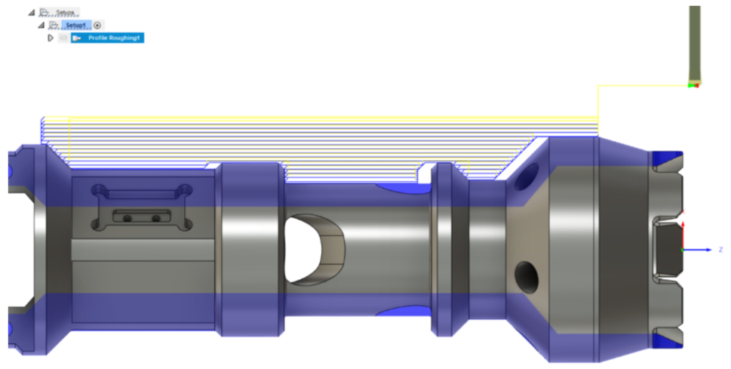
Being a machinist is all about getting creative to produce the highest quality part with the most efficient method possible. Nobody likes restrictions on the tools that they can use. That is why we are opening the turning strategies to allow ALL tools to be used in any strategy- we started with Grooving tools in ‘Profiling Finishing’ and now are ready to open ‘Profile Roughing’ to use the same tools.
Roughing with a Groove tool is generally used to peck out material in an axial motion as these tools don’t handle a side-to-side force very well. But, on much softer materials or plastics these roughing strategies can be utilize with a tool to rough out more complex shapes.
Improved! Grooving Tools in Threading Strategies
Manufacture > Turning tab > Turning Thread
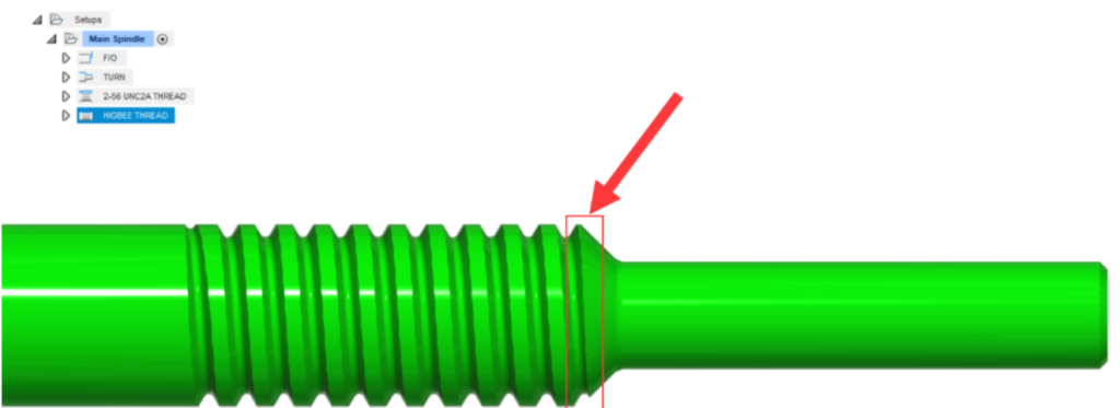
Continuing the idea of opening strategies to allow all tooling, Groove tools can now also be used in Threading Strategies. When running a 2-axis lathe it is common practice to ‘deburr’ your threads. Machinists achieve this by using a technique called ‘Higbee’ or blunt start threading. This process includes taking a flat bottom grooving tool and running it in a threading pattern to remove the first full length of a thread. This is done because usually the first cut of a thread on a taper is not a full pitch width, the Higbee technique removes the material up to the first full thread pitch width. This helps to deburr the thread and prevent cross threading.
The technique of Higbee/Blunt Start threading is typically done by deriving the threading operation and changing a few simple settings.

For example, If you’re cutting a 2-56 UNC2A thread, you want keep your thread depth and pitch the same for the derived operation. If you want to change is the Backside containment, set ‘Apply Back From Front’ and apply an offset of one full pitch (1/56 = 0.0178571”). As a preference, you also have the deburr pass start another full pitch Infront of the cut. Swap out your threading tool for the groove tool and you’re good to go!
New in Preview! Nesting in Manufacture (Extension Preview Feature)
Preferences > Preview > Manufacture > Nesting for Manufacture


If you’re cutting a large number of parts out of flat sheet stock with varying dimensions and prices, Nesting is a crucial piece of the workflow to help eliminate guesswork and minimize waste. Fusion Nesting includes integrated, automated, and associative nesting capabilities to optimize the arrangement of flat parts, both sheet metal and non-sheet metal, on flat raw material in preparation for cutting operations. It allows you to generate nests from your Fusion 360 designs and create toolpaths and NC code to drive your CNC machines – end-to-end seamless workflow all within Fusion 360. With model changes, related nests become “out-of-sync” and can be updated associatively.
While the nesting workflow is ideal if your designs are already in Fusion 360, we completely understand the need to support DXF files. You can use the new app, DXF Import Utility available from the Autodesk App Store, to simplify the process of importing your DXF geometry into Fusion 360.
New in Preview! Delete Passes (Extension Preview Feature)
Preferences > Preview > Manufacture > Delete Passes

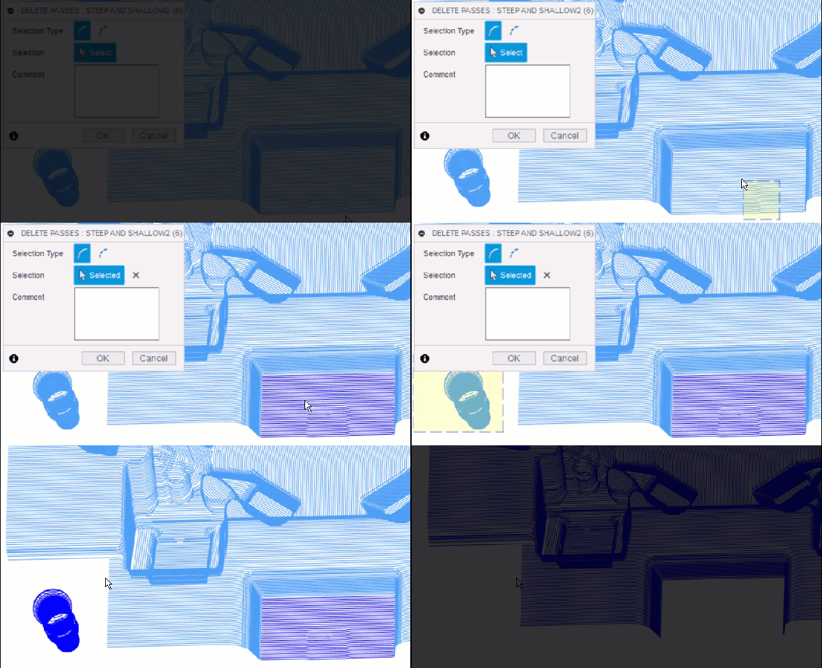
This new Toolpath Modification feature makes it easy for you to delete any undesirable passes or segments in their toolpath. You can quickly turn an unsatisfactory result into a desirable result, without the need for recalculation.
New in Preview! Reduce Air Cutting for 3D Adaptive Clearing
Preferences > Preview > Manufacture > Reduce Air Cutting for 3D Adaptive Clearing


This enhancement is designed to improve the efficiency of a 3D Adaptive Clearing toolpath when undercuts are present in the stock, resulting in reduced air cutting. This can significantly reduce the machining time.
New in Preview! Tolerance Colors
Preferences > Preview > Manufacture > Tolerance Colors

Fusion 360 uses color to indicate when areas of a model exceed upper and lower tolerance values, so you can see at a glance where the model may have too much, or too little, material. Historically, Fusion 360 has used the same colors to mean different things in stock simulation and inspection. Recognizing the potential for confusion, we have introduced a Tolerance Colors setting as a preview feature. When this preview feature is selected, the color conventions for inspection & simulation match, and a legend explaining the color convention is included with the inspection results. It also adds a setting in preferences which allows you to choose between the two historic conventions. In addition it displays out-of-tolerance inspection results from Probe Geometry, Probe WCS and Manual Inspection in orange, and the nominal values for Manual Inspection in black.

[expand title=”See notable fixes“]
- When the feed plane is edited in a Secondary Spindle Chuck Turning operation, the update did not posted until a separate change is made to the operation. The B-value in the output should update to reflect changes to the feed plane regardless of if another change is made to the toolpath., and now it does.
- yanivcPH9F3 experienced some instability with Fusion 360 when he tried to calculate the stock for a Thread Turning Operation with In-Process stock Generation turned on. When he turned In-Process stock off, the operation worked fine. Sorry about this, we looked under the hood and tightened things down. This is now fixed.
- We fixed an issue where if you tried to edit the 2D Contour toolpath and received a warning dialog that read “This operation has missing reference. Do you want to clear the selection?”, clicking YES made Fusion 360 crash.
- evan.lacava told us that Rest Machining wasn’t working properly. When he tried to simulate each individual toolpath, the in-process stock simulation worked fine. When he tried to simulate the whole thing, the in-process stock only showed a square, and the simulation wasn’t removing any material. We cleaned up some code and now it’s fixed.
- Regression: 3D Adaptive “Rest Machining” fails to recognize prior operations when Turning toolpaths are involved
- In Profile Roughing, we realized that the Tool Limit option incorrectly appeared in the Front section. It should really be in the Back section, so we moved it.
- jacob.r.jennings reported that he was getting a dialog asking him if he wanted to clear the selection when he was trying to edit an operation that seemed to have missing geometry in the selection set. We found a bug in the code that was causing this confusing, so we squashed it and now it’s working as expected.
[/expand]
Additive
New! Support for Geetech and XYZ Printing 3D Printers
Manufacture > Additive tab > Machine Library

Fusion Machine library now includes one new Geetech and eight new XYZ Printing 3Dprinters. The post library also has a post associated with these printers, so users can setup the prints and generate G-Code for their machines.
New! Print statistics
Manufacture > Additive tab > Actions Panel > Print Statistics

After generating the toolpath for an Additive Manufacturing Setup with an FFF machine, you will now see the “Print Time” appear as the last object in the browser tree. You can double click on “Print Time” or you can select “Print Statistics” from the “Actions” panel to display the new “Print Statistics” dialog, which contains information about how long the 3D print will take and how much material will be needed during the process. Armed with this knowledge, you may want to edit your print settings and generate a new toolpath to alter print time and/or material consumption for various segments of your 3D Print.
New! Arc Fit Optimization is now out of Preview
Manufacture > Additive tab > Print Settings Panel > Print Settings Editor > G-Code Tab > Arc Fit Optimization

When Arc Fit optimization is enabled, the FFF toolpath generated for additive manufacturing setups contain G2/G3 (Arc/Circle) moves, which reduces the size of the G-Code and produces better 3D prints.
Improved! Printer Limits
Manufacture > Additive Tab > Machine Library > Edit Machine > Limits/Extruder Configurations

In previous versions the printer limits that could be set in the machine configurations were only for informational purposes but had no effect on print settings or toolpath generation. With this update, settings that exceed limits defined in the machine configuration will automatically be reduced to the maximum allowed value during toolpath generation and a warning will be shown to inform the user about the adaption.

Some of the printers in the library also had unrealistic limits predefined. Those were updated to reflect reality more closely as part of this improvement.
Learn more about Additive Manufacturing
API
New! Export a Drawing as a PDF
This is the first bit of implementation for the Drawings environment! You will see a new product and document type now available to support Drawings. The only Drawing specific API available now is to export a PDF, but we would love to hear what other capabilities you would like supported in this environment. This should also make it easier to generally add commands and support UI elements in the Drawing environment by explicitly supporting this “product.”
New! A new id property is now available on a component
This is the internal ID Fusion 360 uses to track components and will become important to some of our future cloud API plans. This ID is guaranteed to be unique within a given Fusion Document only. For example, if you were to export/import or copy an existing Fusion Design the component ID’s in the new file would be the same. This can be convenient though. For external systems and ID’s it should be noted that the combination of DataFile + Version Number + Component ID is truly unique. Alternatively DataFile.versionId + Component ID is another way to get the same result.
New! NURBS Curve Creation addByNurbsCurve
There is an existing method (SketchFittedSplines.addByNurbsCurve) to create a sketch curve from a NURBS curves definition. Because it was creating a spline that fits through points there were some weird side effects with the resulting curve. There’s a new addByNurbsCurve method on the SketchFixedSplines that creates a NURBS curve. The curve created is not editable through the UI but can be used for any operations that use a sketch curve. This is the same type of result you get in the user-interface when you project a curve onto a sketch. The curve isn’t editable because it’s controlled by the entity that was projected. The NURBS definition of the curve can be updated through the API to change the shape of the curve. The user can use the Break Link command to break the relationship, making the curve editable.
Improved! Greater support for Data objects and their IDs
All of the various data related objects now support getting their ID and the collections of those objects now support itemById methods that allows you to easily get an object using the ID. There is also a new findFileById method on the Data object that will find a file using the ID, regardless of the file’s location.
See full what’s new documentation
[expand title=”See notable fixes“]
- An isLinked property has been added to all sketch entities to allow you to check if the curve is defined by another curve and is editable or not.
- Chamfer, Sweep and Sketch Text Enhancements have been added to the API to support the corresponding feature enhancements.
- Jakob reported that a new url was being generated every time you requested a public link for a dataFile. Now if a public link already exists for the file, a new one will not be generated.
[/expand]